STM32通过I2C控制LCD1602显示
STM32通过I2C控制LCD1602
- I2C简介
- HAL函数介绍
- PCF8574+LCD1602介绍
-
- IO扩展:PCF8574
- LCD1602
- 具体实现
-
- CubeMX设置
- 代码
硬件平台:
NUCLEO-STM32F411RE+PCF8574+LCD1602
注意:显示屏背光亮但不显示可能因为对比度不足,可通过电位器调节
I2C简介
I2C总线是由Philips公司开发的一种简单、双向二线制同步串行总线。 它只需要两根线即可在连接于总线上的器件之间传送信息。 主器件用于启动总线传送数据,并产生时钟以开放传送的器件,此时任何被寻址的器件均被认为是从器件. 在总线上主和从、发和收的关系不是恒定的,而取决于此时数据传送方向。
连接方式如下:
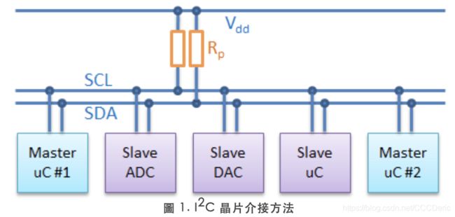
帧地址:I2C总线上的每个设备都有自己的独立地址,主机发起通讯时,通过SDA信号线发送设备地址(SLAVE_ADDRESS)来查找从机。I2C协议规定设备地址可以是7位或10位,实际中7位的地址应用比较广泛。
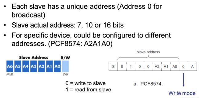
以主机向从机写数据为例,其基本结构如图所示,依次为:
起始信号——从机地址——读写信号——数据位——应答位——… … ——停止位

I2C使用SDA信号线来传输数据,使用SCL信号线进行数据同步。SDA数据线在SCL的每个时钟周期传输一位数据。传输时,SCL为高电平的时候SDA表示的数据有效,即此时的SDA为高电平时表示数据“1”,为低电平时表示数据“0”。当SCL为低电平时,SDA的数据无效,一般在这个时候SDA进行电平切换,为下一次表示数据做好准备。
I2C的数据和地址传输都带响应。响应包括“应答(ACK)”和“非应答(NACK)”两种信号。
作为数据接收端时,当设备(无论主从机)接收到I2C传输的一个字节数据或地址后,若希望对方继续发送数据,则需要向对方发送“应答(ACK)”信号,发送方会继续发送下一个数据;若接收端希望结束数据传输,则向对方发送“非应答(NACK)”信号,发送方接收到该信号后会产生一个停止信号,结束信号传输。
HAL函数介绍
Function name
HAL_StatusTypeDef HAL_I2C_Master_Transmit (I2C_HandleTypeDef * hi2c, uint16_t
DevAddress, uint8_t * pData, uint16_t Size, uint32_t Timeout)
Function description
Transmits in master mode an amount of data in blocking mode.
Parameters
• hi2c: Pointer to a I2C_HandleTypeDef structure that contains the configuration information for the specified I2C.
• DevAddress: Target device address: The device 7 bits address value in datasheet must be shifted to the left before calling the interface
• pData: Pointer to data buffer
• Size: Amount of data to be sent
• Timeout: Timeout duration
Return values
• HAL: status
Function name
HAL_StatusTypeDef HAL_I2C_Master_Receive (I2C_HandleTypeDef * hi2c, uint16_t
DevAddress, uint8_t * pData, uint16_t Size, uint32_t Timeout)
Function description
Receives in master mode an amount of data in blocking mode.
Parameters
• hi2c: Pointer to a I2C_HandleTypeDef structure that contains the configuration information for the specified I2C.
• DevAddress: Target device address: The device 7 bits address value in datasheet must be shifted to the left before calling the interface
• pData: Pointer to data buffer
• Size: Amount of data to be sent
• Timeout: Timeout duration
Return values
• HAL: status
PCF8574+LCD1602介绍
IO扩展:PCF8574
PCF8574是一款并口扩展芯片,它与主控芯片通过IIC接口进行通讯。芯片管脚定义如下:

接线如下:

PCF8574地址使用手册定义如下:
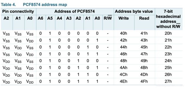
查询硬件地址很简单,如果PCF8574背面对应接口被短接就是0,否则1
LCD1602
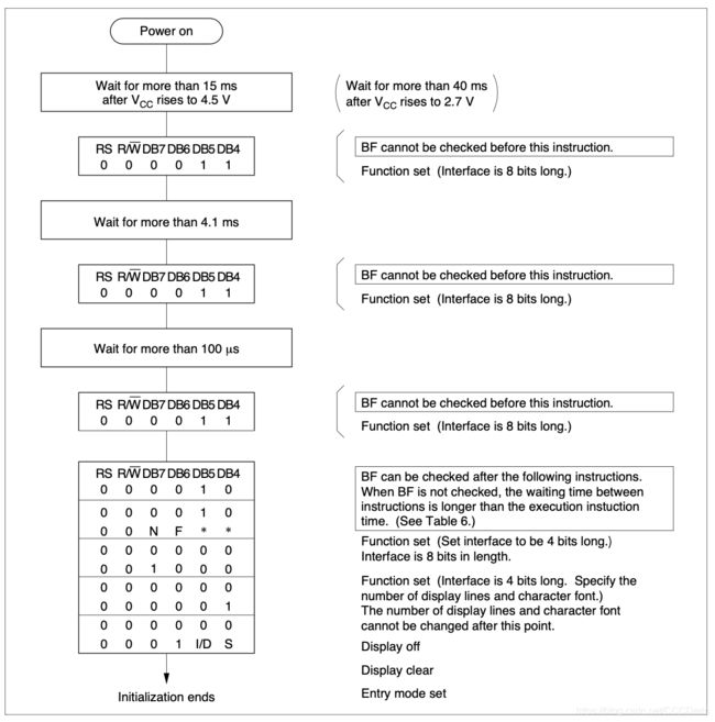
LCD1602的控制芯片(MCU)是HD44780。控制模式有两种-8位模式和4位模式,本文使用4位模式。
功能简介:
Clear Display
Clear display writes space code 20H (character pattern for character code 20H must be a blank pattern) into all DDRAM addresses. It then sets DDRAM address 0 into the address counter, and returns the display to its original status if it was shifted. In other words, the display disappears and the cursor or blinking goes to the left edge of the display (in the first line if 2 lines are displayed). It also sets I/D to 1 (increment mode) in entry mode. S of entry mode does not change.
Return Home
Return home sets DDRAM address 0 into the address counter, and returns the display to its original status if it was shifted. The DDRAM contents do not change.
The cursor or blinking go to the left edge of the display (in the first line if 2 lines are displayed).
Entry Mode Set
I/D: Increments (I/D = 1) or decrements (I/D = 0) the DDRAM address by 1 when a character code is written into or read from DDRAM.
The cursor or blinking moves to the right when incremented by 1 and to the left when decremented by 1. The same applies to writing and reading of CGRAM.
S: Shifts the entire display either to the right (I/D = 0) or to the left (I/D = 1) when S is 1. The display does not shift if S is 0.
If S is 1, it will seem as if the cursor does not move but the display does. The display does not shift when reading from DDRAM. Also, writing into or reading out from CGRAM does not shift the display.
Display On/Off Control
D: The display is on when D is 1 and off when D is 0. When off, the display data remains in DDRAM, but
can be displayed instantly by setting D to 1.
C: The cursor is displayed when C is 1 and not displayed when C is 0. Even if the cursor disappears, the function of I/D or other specifications will not change during display data write. The cursor is displayed using 5 dots in the 8th line for 5 × 8 dot character font selection and in the 11th line for the 5 × 10 dot character font selection.
B: The character indicated by the cursor blinks when B is 1. The blinking is displayed as switching between all blank dots and displayed characters at a speed of 409.6-ms intervals when fcp or fOSC is 250 kHz. The cursor and blinking can be set to display simultaneously. (The blinking frequency changes according to fOSC or the reciprocal of fcp. For example, when fcp is 270 kHz, 409.6 × 250/270 = 379.2 ms.)
Cursor or Display Shift
Cursor or display shift shifts the cursor position or display to the right or left without writing or reading display data. This function is used to correct or search the display. In a 2-line display, the cursor moves to the second line when it passes the 40th digit of the first line. Note that the first and second line displays will shift at the same time.
When the displayed data is shifted repeatedly each line moves only horizontally. The second line display does not shift into the first line position.
The address counter (AC) contents will not change if the only action performed is a display shift.
Function Set
DL: Sets the interface data length. Data is sent or received in 8-bit lengths (DB7 to DB0) when DL is 1, and in 4-bit lengths (DB7 to DB4) when DL is 0.When 4-bit length is selected, data must be sent or received twice.
N: Sets the number of display lines.
F: Sets the character font.
Note: Perform the function at the head of the program before executing any instructions (except for the read busy flag and address instruction). From this point, the function set instruction cannot be executed unless the interface data length is changed.
Set CGRAM Address
Set CGRAM address sets the CGRAM address binary AAAAAA into the address counter. Data is then written to or read from the MPU for CGRAM.
4位模式初始化如下:
具体实现
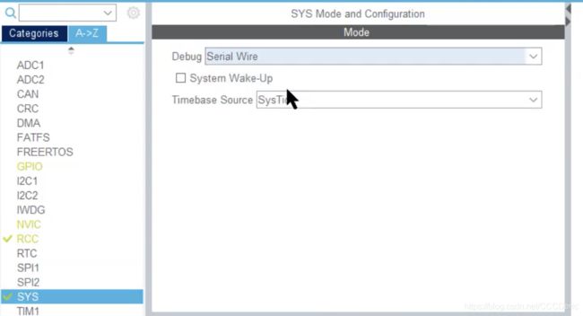
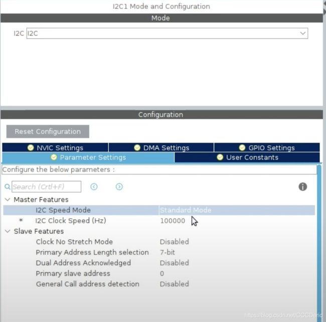
CubeMX设置
I2C:

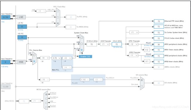
时钟设置:
代码
创建文件i2c-lcd.h:
#include "stm32f4xx_hal.h"
void lcd_init (void);   // initialize lcd
void lcd_send_cmd (char cmd);  // send command to the lcd
void lcd_send_data (char data);  // send data to the lcd
void lcd_send_string (char *str);  // send string to the lcd
void lcd_put_cur(int row, int col); // put cursor at the entered position rol(0 or 1), col(0 - 15)
void lcd_clear (void);
创建文件i2c-lcd.c:
#include "i2c-lcd.h"
#include "main.h"

extern I2C_HandleTypeDef hi2c1;  // change your handler here accordingly
#define SLAVE_ADDRESS_LCD  0x4E // change this according to ur setup

void lcd_send_cmd (char cmd){
	char data_u, data_l;
	uint8_t i2c_frame_data[4];
	data_u = (cmd&0xf0);
	data_l = ((cmd<<4)&0xf0);
	i2c_frame_data[0] = data_u|0x0C;  //en=1, rs=0
	i2c_frame_data[1] = data_u|0x08;  //en=0, rs=0
	i2c_frame_data[2] = data_l|0x0C;  //en=1, rs=0
	i2c_frame_data[3] = data_l|0x08;  //en=0, rs=0
	HAL_I2C_Master_Transmit(&hi2c1, SLAVE_ADDRESS_LCD, (uint8_t *) i2c_frame_data, 4, 100);
	HAL_Delay(1);
}

void lcd_send_data (char data){
	char data_u, data_l;
	uint8_t i2c_frame_data[4];
	data_u = (data&0xf0);
	data_l = ((data<<4)&0xf0);
	i2c_frame_data[0] = data_u|0x0D;  //en=1, rs=0
	i2c_frame_data[1] = data_u|0x09;  //en=0, rs=0
	i2c_frame_data[2] = data_l|0x0D;  //en=1, rs=0
	i2c_frame_data[3] = data_l|0x09;  //en=0, rs=0
	HAL_I2C_Master_Transmit(&hi2c1, SLAVE_ADDRESS_LCD, (uint8_t *) i2c_frame_data, 4, 100);
	HAL_Delay(1);
}

void lcd_clear (void){
	lcd_send_cmd (0x01);  // clear display
	HAL_Delay(1);
}

void lcd_put_cur(int row, int col){
	switch(row){
	case 0:
		col |= 0x80;
		break;
	case 1:
		col |= 0xC0;
		break;
	}
	lcd_send_cmd(col);
}

void lcd_init (void){
    // 4-bit mode initialization
	HAL_Delay(50); // wait for >40ms
	lcd_send_cmd(0x30);
	HAL_Delay(5); // wait for > 4.1ms
	lcd_send_cmd(0x30);
	HAL_Delay(1); // wait for >100us
	lcd_send_cmd(0x30);
	HAL_Delay(10);
	lcd_send_cmd(0x20); // 4-bit mode
	HAL_Delay(10);
    // display initialization
	lcd_send_cmd(0x28); // Function set --> DL = 0 (4-bit mode), N = 1 (2 line display), F = 0 (5x8 characters)
	HAL_Delay(1);
	lcd_send_cmd(0x08); // Display on/off control --> D = 0, C = 0, B = 0 --> display off
	HAL_Delay(1);
	lcd_send_cmd(0x01); // clear display
	HAL_Delay(1);
	lcd_send_cmd(0x06); // Enter mode set --> I/D = 1 (increment cursor) & S = 0 (no shift)
	HAL_Delay(1);
	lcd_send_cmd(0x0E); // Display on /off control --> D = 1, C = 1, B = 0

	HAL_Delay(1);
}

void lcd_send_string (char *str){
    while(*str){lcd_send_data(*str++);}
	HAL_Delay(1);
}
main.c:
  lcd_init();
  lcd_send_string("Hello World!");
  HAL_Delay(1000);
  lcd_put_cur(1, 0);
  lcd_send_string("from Cedr1c");