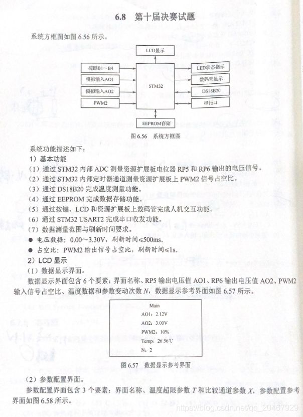
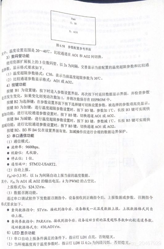
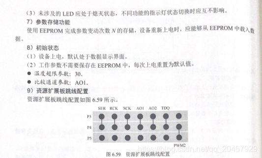
电压、PWM采集、温度18B20读取的实现
毫不夸张的说,第十届蓝桥杯嵌入式国赛赛题出的是最有水平的一届,难度也是最高的一届赛题(第十一届国赛赛题由于只是考了脉冲捕获和脉冲输出,之前有介绍过,本文就是最后一篇过于蓝桥杯国赛赛题的分析)
第十届赛题如下:


本届赛题最难的地方不是数据的采集,而是要让数码管和串口同时工作,要知道,串口和数码管是通用IO口的,虽然可以分时复用,但两条数码管的时钟线都在串口IO上,所以即便分时复用,也会导致在串口发送和接收的过程中数码管显示乱码。
—>相应的本文的解决方法为:在串口使能的时候,只允许其中之一有效,即:串口需要发送数据时要关闭串口接收功能,同理,当串口接收时串口的发送端是无效的。–>原因:由于数码管是74HC595驱动的(可以适当了解下此芯片),它工作与时钟线的上升沿,即RCLK(R:存储寄存器读取):上升沿 移位寄存器进入存储寄存器;下降沿 数据保持不变;SCK(S:送入595):上升沿 数据寄存器数据移位。Q0–>Q1–>Q2–>Q3–>…–>Q7;下降沿 移位寄存器数据不变。也就是说要想让595工作,则需要有时钟线的上升沿,而且是两个时钟线的上升沿。那么本文方法就是当启用串口功能时只让一个IO功能有效,则不会同时改变两个IO口连接的时钟线状态,即完成了相当于锁存的功能。实现方法为:
USART_ITConfig(USART2, USART_IT_RXNE, DISABLE);
USART_Cmd(USART2, DISABLE);
SEG_Init();
SEG_Display();
USART2_GPIO_RXDisable();
USART2_GPIO_TXEnable();
USART_Cmd(USART2, ENABLE);
printf("\r\n\n USART2 AND 7SEG Share GPIO....\r\n");
USART2_GPIO_TXDisable();
USART2_GPIO_RXEnable();
USART_ITConfig(USART2, USART_IT_RXNE, ENABLE);
调用的代码:
串口2
#include "usart2.h"
#include <stdio.h>
static void USART2_NVIC_Configuration(void)
{
NVIC_InitTypeDef NVIC_InitStructure;
NVIC_InitStructure.NVIC_IRQChannel = USART2_IRQn;
NVIC_InitStructure.NVIC_IRQChannelPreemptionPriority = 0;
NVIC_InitStructure.NVIC_IRQChannelSubPriority = NVICPriority_Structure.Usart2;
NVIC_InitStructure.NVIC_IRQChannelCmd = ENABLE;
NVIC_Init(&NVIC_InitStructure);
}
static void USART2_RCC_Configuration(void)
{
RCC_APB2PeriphClockCmd(RCC_APB2Periph_GPIOA, ENABLE);
RCC_APB1PeriphClockCmd(RCC_APB1Periph_USART2, ENABLE);
}
static void USART2_GPIO_Configuration(void)
{
GPIO_InitTypeDef GPIO_InitStructure;
GPIO_InitStructure.GPIO_Pin = GPIO_Pin_3;
GPIO_InitStructure.GPIO_Mode = GPIO_Mode_IN_FLOATING;
GPIO_Init(GPIOA, &GPIO_InitStructure);
GPIO_InitStructure.GPIO_Pin = GPIO_Pin_2;
GPIO_InitStructure.GPIO_Speed = GPIO_Speed_50MHz;
GPIO_InitStructure.GPIO_Mode = GPIO_Mode_AF_PP;
GPIO_Init(GPIOA, &GPIO_InitStructure);
}
void USART2_GPIO_TXEnable(void)
{
GPIO_InitTypeDef GPIO_InitStructure;
GPIO_InitStructure.GPIO_Pin = GPIO_Pin_2;
GPIO_InitStructure.GPIO_Speed = GPIO_Speed_50MHz;
GPIO_InitStructure.GPIO_Mode = GPIO_Mode_AF_PP;
GPIO_Init(GPIOA, &GPIO_InitStructure);
}
void USART2_GPIO_TXDisable(void)
{
GPIO_InitTypeDef GPIO_InitStructure;
GPIO_InitStructure.GPIO_Pin = GPIO_Pin_2;
GPIO_InitStructure.GPIO_Speed = GPIO_Speed_50MHz;
GPIO_InitStructure.GPIO_Mode = GPIO_Mode_Out_PP;
GPIO_Init(GPIOA, &GPIO_InitStructure);
GPIO_ResetBits(GPIOA,GPIO_Pin_2);
}
void USART2_GPIO_RXEnable(void)
{
GPIO_InitTypeDef GPIO_InitStructure;
GPIO_InitStructure.GPIO_Pin = GPIO_Pin_3;
GPIO_InitStructure.GPIO_Mode = GPIO_Mode_IN_FLOATING;
GPIO_Init(GPIOA, &GPIO_InitStructure);
}
void USART2_GPIO_RXDisable(void)
{
GPIO_InitTypeDef GPIO_InitStructure;
GPIO_InitStructure.GPIO_Pin = GPIO_Pin_3;
GPIO_InitStructure.GPIO_Speed = GPIO_Speed_50MHz;
GPIO_InitStructure.GPIO_Mode = GPIO_Mode_Out_PP;
GPIO_Init(GPIOA, &GPIO_InitStructure);
GPIO_ResetBits(GPIOA,GPIO_Pin_3);
}
static void USART2_Configuration(void)
{
USART_InitTypeDef USART_InitStructure;
USART_InitStructure.USART_BaudRate = 9600;
USART_InitStructure.USART_WordLength = USART_WordLength_8b;
USART_InitStructure.USART_StopBits = USART_StopBits_1;
USART_InitStructure.USART_Parity = USART_Parity_No;
USART_InitStructure.USART_HardwareFlowControl = USART_HardwareFlowControl_None;
USART_InitStructure.USART_Mode = USART_Mode_Rx | USART_Mode_Tx;
USART_Init(USART2, &USART_InitStructure);
USART_ITConfig(USART2, USART_IT_RXNE, ENABLE);
USART_Cmd(USART2, ENABLE);
}
void USART2_Init(void)
{
USART2_NVIC_Configuration();
USART2_RCC_Configuration();
USART2_GPIO_Configuration();
USART2_Configuration();
}
int fputc(int ch, FILE *f)
{
USART_SendData(USART2, (uint8_t) ch);
while (USART_GetFlagStatus(USART2, USART_FLAG_TC) == RESET)
{}
return ch;
}
STRUCT_USART2 USART2_Structure;
void USART2_Interrupt(void)
{
u8 USART2_Rec;
if(USART_GetITStatus(USART2, USART_IT_RXNE) != RESET)
{
USART_ClearITPendingBit(USART2,USART_IT_RXNE);
USART2_Rec = USART_ReceiveData(USART2);
if(USART2_Rec == 'S')
{
USART2_Structure.RxCounter = 0;
USART2_Structure.IS_Start = TRUE;
}
if(USART2_Structure.IS_Start == TRUE)
USART2_Structure.RxBuffer[USART2_Structure.RxCounter++] = USART_ReceiveData(USART2);
if(USART2_Rec == '\r')
{
USART2_Structure.IS_Start = FALSE;
USART2_Structure.IS_Finish = TRUE;
}
if(USART2_Structure.RxCounter > USART2_BUFFMAX)
{
USART2_Structure.RxCounter = 0;
USART2_Structure.IS_Start = FALSE;
USART2_Structure.IS_Finish = TRUE;
}
}
}
数码管驱动:
#ifndef __7seg_h
#define __7seg_h

#include "stm32f10x.h"

#define SER_H GPIO_SetBits(GPIOA,GPIO_Pin_1)
#define SER_L GPIO_ResetBits(GPIOA,GPIO_Pin_1)

#define RCK_H GPIO_SetBits(GPIOA,GPIO_Pin_2)
#define RCK_L GPIO_ResetBits(GPIOA,GPIO_Pin_2)

#define SCK_H GPIO_SetBits(GPIOA,GPIO_Pin_3)
#define SCK_L GPIO_ResetBits(GPIOA,GPIO_Pin_3)

#define  Seg_Code_A     10
#define  Seg_Code_C     12
#define  Seg_Code_O     0
#define  Seg_Code_Off   16
#define  Seg_Code_spot  17

typedef struct {
   uint8_t bit3;
   uint8_t bit2;
   uint8_t bit1;
}STRUCT_7SEG;
extern STRUCT_7SEG SEG_Structure;

void SEG_Init(void);
void SEG_Display(void);

#endif
#include "7seg.h"
uc8 Seg7[] = { 0x3f,0x06,0x5b,0x4f,0x66,0x6d,0x7d,0x07,0x7f,0x6f,
0x77,0x7c, 0x39,0x4f,0x79,0x78,
0x00,
0x3f|0x80,0x06|0x80,0x5b|0x80,0x4f|0x80,0x66|0x80,0x6d|0x80,0x7d|0x80,0x07|0x80,0x7f|0x80,0x6f|0x80};
void SEG_Init(void)
{
GPIO_InitTypeDef GPIO_InitStructure;
RCC_APB2PeriphClockCmd(RCC_APB2Periph_GPIOA, ENABLE);
GPIO_InitStructure.GPIO_Pin = GPIO_Pin_1 | GPIO_Pin_2 | GPIO_Pin_3;
GPIO_InitStructure.GPIO_Mode = GPIO_Mode_Out_PP;
GPIO_InitStructure.GPIO_Speed = GPIO_Speed_2MHz;
GPIO_Init(GPIOA, &GPIO_InitStructure);
RCK_L;
SCK_L;
}
STRUCT_7SEG SEG_Structure;
void SEG_Display(void)
{
u8 i = 0;
u8 SEG_DisBuff = Seg7[Seg_Code_Off];
SEG_DisBuff = Seg7[SEG_Structure.bit3];
for(i = 0;i < 8; i++)
{
if(SEG_DisBuff & 0x80)
SER_H;
else
SER_L;
SCK_H;
SEG_DisBuff = SEG_DisBuff << 1;
SCK_L;
}
SEG_DisBuff = Seg7[SEG_Structure.bit2];
for(i = 0;i < 8; i++)
{
if(SEG_DisBuff & 0x80)
SER_H;
else
SER_L;
SCK_H;
SEG_DisBuff = SEG_DisBuff << 1;
SCK_L;
}
SEG_DisBuff = Seg7[SEG_Structure.bit1];
for(i = 0;i < 8; i++)
{
if(SEG_DisBuff & 0x80)
SER_H;
else
SER_L;
SCK_H;
SEG_DisBuff = SEG_DisBuff << 1;
SCK_L;
}
RCK_H;
SEG_DisBuff = Seg7[Seg_Code_Off];
RCK_L;
}


