ESP32-pico-kit 串口通信 与 蓝牙串口
文章目录
- 一、串口及ESP32介绍
-
- 1.串口通信
- 2.ESP32-pico-kit
- 二、串口UART
-
- 1.串口引脚
- 2.串口常用函数
-
- (1)开启串口
- (2)关闭串口
- (3)输出数据
- (4)读取数据
- (5)判断缓冲区状态
- (6)更新波特率
- 三、蓝牙串口BluetoothSerial
- 四、蓝牙串口实验SerialToSerialBT
- 附 其他参考资料
一、串口及ESP32介绍
1.串口通信
关于串口通信的相关知识,可以参考如下几篇文章。
串口通信基础(一)——串行与并行通信,同步与异步通信
串口通信基础(二)——传输方式(方向)、错误校验、传输速率与传输距离
串口通信接口标准(三)——RS232
串口通信接口标准(四)——RS422、RS485
注意在接线时应注意 RX 和 TX 交叉接线。
2.ESP32-pico-kit
使用的开发板为乐鑫公司的 ESP32-pico-kit,相关文档参见官网技术文档以及入门指南。
二、串口UART
1.串口引脚
ESP32 有三个串口,其中 UART1 用于 Flash 读/写:
| 串口名 | RX引脚 | TX引脚 |
|---|---|---|
| Serial | 3 | 1 |
| Serial1 | 9 | 10 |
| Serial2 | 16 | 17 |
在 HardwareSerial.cpp 和 HardwareSerial.h 文件中定义了有关串口的相关信息,两个文件所在文件夹的路径为 .\Arduino15\packages\esp32\hardware\esp32\1.0.3\cores\esp32。
在文件 HardwareSerial.h 中定义了 HardwareSerial 类,该类继承了 Stream 类,Stream 类继承了 Print 类
class HardwareSerial: public Stream
class Stream: public Print
在文件 HardwareSerial.h 中声明了三个串口对象。
#if !defined(NO_GLOBAL_INSTANCES) && !defined(NO_GLOBAL_SERIAL)
extern HardwareSerial Serial;
extern HardwareSerial Serial1;
extern HardwareSerial Serial2;
#endif
在文件 HardwareSerial.cpp 中定义了串口的引脚,代码片段如下所示
...
#ifndef RX1
#define RX1 9
#endif

#ifndef TX1
#define TX1 10
#endif

#ifndef RX2
#define RX2 16
#endif

#ifndef TX2
#define TX2 17
#endif
...

void HardwareSerial::begin(unsigned long baud, uint32_t config, int8_t rxPin, int8_t txPin, bool invert, unsigned long timeout_ms)
{
	...
    if(_uart_nr == 0 && rxPin < 0 && txPin < 0) {
        rxPin = 3;
        txPin = 1;
    }
    if(_uart_nr == 1 && rxPin < 0 && txPin < 0) {
        rxPin = RX1;
        txPin = TX1;
    }
    if(_uart_nr == 2 && rxPin < 0 && txPin < 0) {
        rxPin = RX2;
        txPin = TX2;
    }
    ...
}
2.串口常用函数
(1)开启串口
void begin(unsigned long baud, uint32_t config=SERIAL_8N1, int8_t rxPin=-1, int8_t txPin=-1, bool invert=false, unsigned long timeout_ms = 20000UL);
功能:开启串口。
参数:仅有波特率需要指定,其余参数均有默认值。
第二个参数 config 为数字位、校验位、停止位的配置,SERIAL_8N1 表示8个数字位,0个校验位,1个停止位。其余可选配置如下表所示:
| config | 数据位 | 校验位 | 停止位 | config | 数据位 | 校验位 | 停止位 |
|---|---|---|---|---|---|---|---|
| SERIAL_5N1 | 5 | 无 | 1 | SERIAL_5E2 | 5 | 偶 | 2 |
| SERIAL_6N1 | 6 | 无 | 1 | SERIAL_6E2 | 6 | 偶 | 2 |
| SERIAL_7N1 | 7 | 无 | 1 | SERIAL_7E2 | 7 | 偶 | 2 |
| SERIAL_8N1 | 8 | 无 | 1 | SERIAL_8E2 | 8 | 偶 | 2 |
| SERIAL_5N2 | 5 | 无 | 2 | SERIAL_5O1 | 5 | 奇 | 1 |
| SERIAL_6N2 | 6 | 无 | 2 | SERIAL_6O1 | 6 | 奇 | 1 |
| SERIAL_7N2 | 7 | 无 | 2 | SERIAL_7O1 | 7 | 奇 | 1 |
| SERIAL_8N2 | 8 | 无 | 2 | SERIAL_8O1 | 8 | 奇 | 1 |
| SERIAL_5E1 | 5 | 偶 | 1 | SERIAL_5O2 | 5 | 奇 | 2 |
| SERIAL_6E1 | 6 | 偶 | 1 | SERIAL_6O2 | 6 | 奇 | 2 |
| SERIAL_7E1 | 7 | 偶 | 1 | SERIAL_7O2 | 7 | 奇 | 2 |
| SERIAL_8E1 | 8 | 偶 | 1 | SERIAL_8O2 | 8 | 奇 | 2 |
(2)关闭串口
void end();
功能:关闭串口。
参数:无。
(3)输出数据
size_t print(...);//在print类中定义
size_t println(...);//在print类中定义
size_t write(uint8_t);
功能:串口输出数据,写入字符数据到串口。println 输出时带一个换行字符。
区别:在发送数值类型参数时,Serial.print() 与 Serial.println() 发送的是字符,Serial.write() 发送的是字节。可以参考Serial.print()函数与Serial.write()函数的区别。
(4)读取数据
int peek(void);
int read(void);
功能:读取串口数据,一次读一个字符。串口接收到的数据都会暂时存放在接收缓冲区中,使用 read() 与 peek() 都是从接收缓冲区中读取数据。
区别:使用 read() 读取数据后,会将该数据从接收缓冲区移除;而使用 peek() 读取时,不会移除接收缓冲区中的数据。
(5)判断缓冲区状态
int available(void);
功能:判断串口缓冲区的状态,返回从串口缓冲区读取的字节数。
(6)更新波特率
void updateBaudRate(unsigned long baud);
功能:更新波特率。
参数:新的波特率。
三、蓝牙串口BluetoothSerial
ESP32 自带蓝牙和 WiFi 功能,为方便使用,将蓝牙配置成蓝牙串口的形式。
在 .\Arduino15\packages\esp32\hardware\esp32\1.0.3\libraries\BluetoothSerial\src 文件夹中找到的 BluetoothSerial.h 和 BluetoothSerial.cpp 文件,在 .h 中定义了如下的属性和方法。
class BluetoothSerial: public Stream
{
    public:

        BluetoothSerial(void);
        ~BluetoothSerial(void);

        bool begin(String localName=String());
        int available(void);
        int peek(void);
        bool hasClient(void);
        int read(void);
        size_t write(uint8_t c);
        size_t write(const uint8_t *buffer, size_t size);
        void flush();
        void end(void);
        esp_err_t register_callback(esp_spp_cb_t * callback);

    private:
        String local_name;

};
注意:与 Serial 不同的是,BluetoothSerial.begin 的参数为蓝牙名称。
四、蓝牙串口实验SerialToSerialBT
打开 ESP32 例程中的 SerialToSerialBT,代码如下所示:
#include "BluetoothSerial.h"

//是否配置了蓝牙串口,即是否编译过BluetoothSerial相关文件
#if !defined(CONFIG_BT_ENABLED) || !defined(CONFIG_BLUEDROID_ENABLED)
#error Bluetooth is not enabled! Please run `make menuconfig` to and enable it
#endif

BluetoothSerial SerialBT;

void setup() {
  Serial.begin(115200);//此处使用Serial,RX - pin3,TX - pin1
  SerialBT.begin("ESP32test"); //Bluetooth device name
  Serial.println("The device started, now you can pair it with bluetooth!");
}

//实现了蓝牙与串口的消息互发
void loop() {
  if (Serial.available()) {
    SerialBT.write(Serial.read());
  }
  if (SerialBT.available()) {
    Serial.write(SerialBT.read());
  }
  delay(20);
}
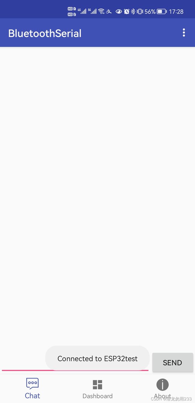
实验过程:先用手机连接蓝牙 ESP32test (代码中设置的蓝牙名),然后用串口调试助手发送 “123456” ,看手机蓝牙是否可以输出;再用手机蓝牙发送 “78910” ,看串口调试助手是否能正确打印。
实验截图如下:


至此,得到了预期的结果,实验成功。
实验中遇到的问题:如果把串口和下载器同时插在电脑上,编译上传会报错,编译器提示

串口持续输出:

解决方式:烧录的时候不接USB转TTL模块,手机连接好蓝牙之后,再连接。
附 其他参考资料
一些参考资料在本文中已经通过超链接的方式引用,除此以外,还有参考了如下文章:
玩转 ESP32 + Arduino (三) GPIO和串口
串口的一些高级用法