基于FPGA的串口传图SRAM缓存VGA显示
简介
在DE2开发板上使用串口接收PC发送的640*480分辨率灰度图,存入SRAM,通过VGA进行显示。
开发板:DE2
型号:EP2C35F672C6
开发工具:Quartus II 13.0 + Modelsim 10.5 SE
全局时钟: 50M
VGA时钟:25M
SRAM大小:256k*16bit,总共512kb
目前还不会用SDRAM,先从简单的SRAM入手。
由于640*480分辨率的24位彩色图片需要900kb,SRAM装不下,所以使用8位灰度图(300kb)。
该SRAM为256k*16bit,为了存下300kb的灰度图,我将其包装为512k*8bit
RTL视图

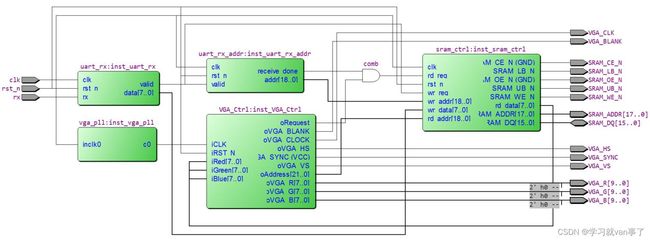
一共五个模块:PLL、串口接收、写入地址计数、SRAM驱动、VGA驱动
PLL模块为VGA驱动模块提供25M时钟。
串口接收模块接收来自PC发送的图片数据。
写入地址计数模块根据接收到的数据,产生写入地址,并在接收完整张图片后,输出receive_done信号,允许VGA从SRAM读取数据。
SRAM驱动模块对SRAM芯片进行读写。
VGA驱动模块产生VGA时序显示图片。
串口接收模块
波特率:115200
数据位:8
校验:无
停止位:1
module uart_rx(
    // clk, rst_n
    input               clk,
    input               rst_n,

    // uart rx
    input               rx,

    // valid data output
    output reg          valid,
    output reg [7:0]    data
);
    parameter CLK_FRE      = 50_000_000;
    parameter BAUD_RATE    = 115200;       // 默认115200波特率
    parameter cnt_baud_max = CLK_FRE / BAUD_RATE - 1;  // 115200波特率下是434时钟周期一波特

    // 打两拍防止亚稳态,rx_3用于检测rx下降沿
    reg         rx_1;
    reg         rx_2;
    reg         rx_3;
    // 工作使能
    reg         work_ena;
    // 波特计数器 比特计数器
    reg [8:0]   cnt_baud;
    reg [4:0]   cnt_bit;
    // 计数器使能、清零
    wire        cnt_baud_ena;
    wire        cnt_baud_end;
    wire        cnt_bit_ena;
    wire        cnt_bit_end;
    // data移位寄存器
    reg [7:0]   data_shift;
    // valid打一拍再输出,和data同步输出
    reg         valid_reg;

    // 打两拍防止亚稳态
    always @(posedge clk, negedge rst_n) begin
        if(!rst_n) begin
            rx_1 <= 0;
            rx_2 <= 0;
            rx_3 <= 0;
        end else begin
            rx_1 <= rx;
            rx_2 <= rx_1;
            rx_3 <= rx_2;
        end
    end

    // rx下降沿检测,出现下降沿开始工作,接收完数据结束工作
    always @(posedge clk, negedge rst_n) begin
        if(!rst_n) begin
            work_ena <= 0;
        end else begin
            if(~rx_2 & rx_3)
                work_ena <= 1;
            else if(cnt_bit_ena && cnt_bit_end)
                work_ena <= 0;
        end
    end

    // 波特计数器
    always @(posedge clk, negedge rst_n) begin
        if(!rst_n)
            cnt_baud <= 0;
        else if(cnt_baud_ena) begin
            if(cnt_baud_end)
                cnt_baud <= 0;
            else
                cnt_baud <= cnt_baud + 1;
        end else
            cnt_baud <= 0;
    end

    assign cnt_baud_ena = work_ena;
    assign cnt_baud_end = (cnt_baud == cnt_baud_max);

    // 比特计数器
    always @(posedge clk, negedge rst_n) begin
        if(!rst_n)
            cnt_bit <= 0;
        else if(cnt_bit_ena) begin
            if(cnt_bit_end)
                cnt_bit <= 0;
            else
                cnt_bit <= cnt_bit + 1;
        end
    end

    assign cnt_bit_ena = (cnt_baud == cnt_baud_max / 2);
    assign cnt_bit_end = (cnt_bit == 8);

    // data移位寄存器
    always @(posedge clk, negedge rst_n) begin
        if(!rst_n)
            data_shift <= 0;
        else if(cnt_bit_ena)
            data_shift <= {rx_2, data_shift[7:1]};
    end

    // 内部valid_reg有效信号
    always @(posedge clk, negedge rst_n) begin
        if(!rst_n) begin
            valid_reg <= 0;
        end
        else if(cnt_bit_ena && cnt_bit_end)
            valid_reg <= 1;
        else
            valid_reg <= 0;
    end

    // valid_reg 打一拍再输出,和data同步
    always @(posedge clk, negedge rst_n) begin
        if(!rst_n)
            valid <= 0;
        else
            valid <= valid_reg;
    end

    // 输出data
    always @(posedge clk, negedge rst_n) begin
        if(!rst_n)
            data <= 0;
        else if(valid_reg)
            data <= data_shift;
    end

endmodule
写入地址计数模块
根据串口接收模块接收到的数据,输出该数据需要写入SRAM的地址,接收完整张图片后,拉高receive_done信号,允许VGA模块读取SRAM中的数据。
module uart_rx_addr(
    input clk,
    input rst_n,

    // uart_rx side
    input valid,

    // sram_ctrl side
    output reg receive_done,
    output reg [18:0] addr
);

    wire cnt_end = (addr == 640 * 480);

    always @(posedge clk, negedge rst_n) begin
        if(!rst_n)
            addr <= 0;
        else if(valid) begin
            if(cnt_end)
                addr <= 0;
            else
                addr <= addr + 1;
        end
    end

    // 串口传完整张图后,拉高receive_done,允许vga从sram中读取数据
    always @(posedge clk, negedge rst_n) begin
        if(!rst_n)
            receive_done <= 0;
        else if(cnt_end)
            receive_done <= 1;
    end

endmodule
SRAM驱动模块
该SRAM为256k*16bit,为了存下300kb的灰度图,我将其包装为512k*8bit,写优先。
包装方法:地址低于256k的数据写入SRAM的数据位低8位,地址高于高256kb数据写入SRAM的数据位高8位
module sram_ctrl(
    input               clk,
    input               rst_n,

    // wr
    input               wr_req,
    input   [18:0]      wr_addr,
    input   [7:0]       wr_data,

    // rd
    input               rd_req,
    input   [18:0]      rd_addr,
    output reg  [7:0]   rd_data,

    // sram side
    output  [17:0]      SRAM_ADDR,
    inout   [15:0]      SRAM_DQ,
    output              SRAM_WE_N,
    output              SRAM_OE_N,
    output              SRAM_UB_N,
    output              SRAM_LB_N,
    output              SRAM_CE_N
);
    assign SRAM_CE_N = 0;
    assign SRAM_OE_N = 0;

    assign SRAM_DQ   = wr_req ? (SRAM_LB_N ? {wr_data, 8'hzz} : {8'hzz, wr_data}) : 16'hzzzz;
    assign SRAM_WE_N = ~wr_req;

    assign SRAM_ADDR = wr_req ? wr_addr[17:0] : rd_addr[17:0];

    // 将地址最高位作为256k分界线
    // 地址低于256k的数据写入SRAM的低8位,地址高于高256kb数据写入SRAM的高8位
    assign SRAM_LB_N = wr_req ? wr_addr[18] : rd_addr[18];
    assign SRAM_UB_N = ~SRAM_LB_N;

    // rd_data
    always @(posedge clk, negedge rst_n) begin
        if(!rst_n)
            rd_data <= 0;
        else if(rd_req) begin
            if(SRAM_LB_N)
                rd_data <= SRAM_DQ[15:8];
            else
                rd_data <= SRAM_DQ[7:0];
        end
    end

endmodule
VGA驱动模块
使用友晶官方的VGA驱动模块,稍作修改,将输入输出的RGB信号从10位宽改为8位宽。
module	VGA_Ctrl	(	//	Host Side
						iRed,
						iGreen,
						iBlue,
						oCurrent_X,
						oCurrent_Y,
						oAddress,
						oRequest,
						//	VGA Side
						oVGA_R,
						oVGA_G,
						oVGA_B,
						oVGA_HS,
						oVGA_VS,
						oVGA_SYNC,
						oVGA_BLANK,
						oVGA_CLOCK,
						//	Control Signal
						iCLK,
						iRST_N	);
//	Host Side
input		[7:0]	iRed;
input		[7:0]	iGreen;
input		[7:0]	iBlue;
output		[21:0]	oAddress;
output		[10:0]	oCurrent_X;
output		[10:0]	oCurrent_Y;
output				oRequest;
//	VGA Side
output		[7:0]	oVGA_R;
output		[7:0]	oVGA_G;
output		[7:0]	oVGA_B;
output	reg			oVGA_HS;
output	reg			oVGA_VS;
output				oVGA_SYNC;
output				oVGA_BLANK;
output				oVGA_CLOCK;
//	Control Signal
input				iCLK;
input				iRST_N;
//	Internal Registers
reg			[10:0]	H_Cont;
reg			[10:0]	V_Cont;

//	Horizontal	Parameter
parameter	H_FRONT	=	16;
parameter	H_SYNC	=	96;
parameter	H_BACK	=	48;
parameter	H_ACT	=	640;
parameter	H_BLANK	=	H_FRONT+H_SYNC+H_BACK;
parameter	H_TOTAL	=	H_FRONT+H_SYNC+H_BACK+H_ACT;

//	Vertical Parameter
parameter	V_FRONT	=	11;
parameter	V_SYNC	=	2;
parameter	V_BACK	=	31;
parameter	V_ACT	=	480;
parameter	V_BLANK	=	V_FRONT+V_SYNC+V_BACK;
parameter	V_TOTAL	=	V_FRONT+V_SYNC+V_BACK+V_ACT;

assign	oVGA_SYNC	=	1'b1;			//	This pin is unused.
assign	oVGA_BLANK	=	~((H_Cont=H_BLANK && H_Cont=V_BLANK && V_Cont=H_BLANK)	?	H_Cont-H_BLANK	:	11'h0	;
assign	oCurrent_Y	=	(V_Cont>=V_BLANK)	?	V_Cont-V_BLANK	:	11'h0	;

//	Horizontal Generator: Refer to the pixel clock
always@(posedge iCLK or negedge iRST_N)
begin
	if(!iRST_N)
	begin
		H_Cont		<=	0;
		oVGA_HS		<=	1;
	end
	else
	begin
		if(H_Cont
顶层模块
顶层模块例化所有模块进行连线,和上面的RTL图一致
module uart_sram_vga(
    input               clk,
    input               rst_n,

    // uart side
    input               rx,

    // sram side
    output  [17:0]      SRAM_ADDR,
    inout   [15:0]      SRAM_DQ,
    output              SRAM_WE_N,
    output              SRAM_OE_N,
    output              SRAM_UB_N,
    output              SRAM_LB_N,
    output              SRAM_CE_N,

    // vga side
    output              VGA_HS,
    output              VGA_VS,
    output      [9:0]   VGA_R,
    output      [9:0]   VGA_G,
    output      [9:0]   VGA_B,
    output              VGA_CLK,
    output              VGA_BLANK,
    output              VGA_SYNC
);
    // 用不上
    assign {VGA_R[1:0], VGA_G[1:0], VGA_B[1:0]} = 0;

    // pll输出25M时钟给vga_ctrl
    wire            clk_25;

    // uart接收到的数据和有效位
    wire            valid;
    wire    [7:0]   data;

    // wr_addr:数据的写入地址,uart接收完数据后拉高receive_done
    wire    [18:0]  wr_addr;
    wire            receive_done;

    // vga_ctrl输出的坐标、地址、请求、rgb
    wire    [9:0]   x;
    wire    [9:0]   y;
    wire    [21:0]  address;
    wire            oRequest;
	wire 	[7:0]   R,G,B;

    // 从sram中读取的数据
    wire    [7:0]   rd_data;

    vga_pll inst_vga_pll (
        .inclk0 (clk),
        .c0     (clk_25)
    );

    uart_rx inst_uart_rx (
        .clk   (clk),
        .rst_n (rst_n),
        .rx    (rx),
        .valid (valid),
        .data  (data)
    );

    uart_rx_addr inst_uart_rx_addr (
        .clk          (clk),
        .rst_n        (rst_n),
        .valid        (valid),
        .receive_done (receive_done),
        .addr         (wr_addr)
    );

    sram_ctrl inst_sram_ctrl (
        .clk       (clk),
        .rst_n     (rst_n),
        .wr_req    (valid),
        .wr_addr   (wr_addr),
        .wr_data   (data),
        .rd_req    (receive_done & oRequest),
        .rd_addr   (address),
        .rd_data   (rd_data),
        .SRAM_ADDR (SRAM_ADDR),
        .SRAM_DQ   (SRAM_DQ),
        .SRAM_WE_N (SRAM_WE_N),
        .SRAM_OE_N (SRAM_OE_N),
        .SRAM_UB_N (SRAM_UB_N),
        .SRAM_LB_N (SRAM_LB_N),
        .SRAM_CE_N (SRAM_CE_N)
    );

    VGA_Ctrl inst_VGA_Ctrl (
        .iRed       (rd_data),
        .iGreen     (rd_data),
        .iBlue      (rd_data),
        .oCurrent_X (x),
        .oCurrent_Y (y),
        .oAddress   (address),
        .oRequest   (oRequest),
        .oVGA_R     (VGA_R[9:2]),
        .oVGA_G     (VGA_G[9:2]),
        .oVGA_B     (VGA_B[9:2]),
        .oVGA_HS    (VGA_HS),
        .oVGA_VS    (VGA_VS),
        .oVGA_SYNC  (VGA_SYNC),
        .oVGA_BLANK (VGA_BLANK),
        .oVGA_CLOCK (VGA_CLK),
        .iCLK       (clk_25),
        .iRST_N     (rst_n)
    );
endmodule
结果分析
图片选择友晶资料盘里的图片,分辨率640*480,将其转灰度图用于实验。
仿真就不放了,直接放上板验证:
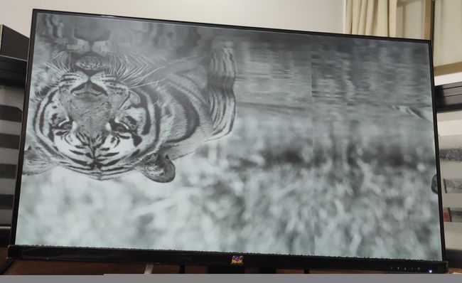
用正点原子的XCOM串口软件发送bmp图片,实验结果如下:

图像上下反转了,而且左右也有错位,说明直接使用串口软件发送bmp文件是不对的。
网上查了很多FPGA串口传图的代码,他们都喜欢自己写一个串口程序来传图,但我太菜了,不会写,他们的程序我也不好用,因为我要传灰度图。
解决方法:将图片转存为hex文件,然后用串口软件发送hex文件。
方式1:matlab
gray = imread('gray_640_480.bmp');
f = fopen('gray_640_480.hex', 'w+');
for y = 1:480
    for x = 1:640
        fprintf(f, '%x', gray(y, x));
    end
end
fclose(f);
方式2:python+opencv
import cv2 as cv
gray = cv.imread('gray_640_480.bmp', cv.IMREAD_GRAYSCALE)
f = open("gray_640_480.hex", "w+")
for y in range(0, 480):
    for x in range(0, 640):
    	# 记得去掉0x开头
        hex_data = hex(gray[y][x])[2:4]
        f.write(hex_data)
f.close()
执行上述代码后,只是将bmp文件转化为了hex文本,其内容还是ASCII字符,2位十六进制数对应1字节,此时的hex文件大小(600kb)是bmp文件大小(300kb)的2倍。
接下来需要执行最后一步:以十六进制编码保存文件,我用的是sublime编辑器,打开hex文件,选择文件->以…编码保存->十六进制
执行完最后一步,hex文件大小变成300kb了,转hex完毕。
之后再用串口软件发送该hex文件即可,实验结果如下,与原图一致:
