【OpenCV-Python】教程:6-2 Pose Estimation (姿态估计)
OpenCV Python Pose Estimation (姿态估计)
【目标】
- 利用calib3d模块在图像中创建一些3D效果。
【理论】
这是一小部分。在上一节中,已经找到了摄像机矩阵,失真系数等。给定一个图案图像,我们可以利用上面的信息来计算它的姿态,或者物体在空间中的位置,比如它是如何旋转的,它是如何位移的等等。对于平面物体,我们可以假设Z=0,这样,现在的问题是如何将相机放置在空间中以看到我们的模式图像。因此,如果我们知道物体在空间中的位置,我们就可以在其中绘制一些2D图来模拟3D效果。让我们看看怎么做。
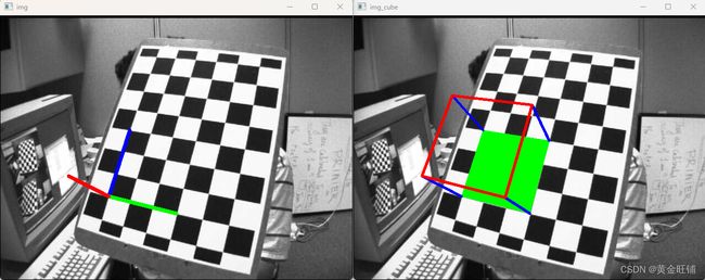
我们的问题是,我们想要在棋盘的第一个角上绘制3D坐标轴(X, Y, Z轴)。X轴为蓝色,Y轴为绿色,Z轴为红色。所以实际上,Z轴应该是垂直于棋盘平面的。
【代码】
在上一章节中,以下代码可以用
############## 保存参数
np.savez("left.npz", mtx=mtx, dist=dist,rvecs=rvecs,tvecs=tvecs )
保存相机矩阵参数和失真参数等;
可以用以下代码提取保存的参数
npzfile = np.load("left.npz")
sorted(npzfile.files)
import numpy as np
import cv2
import glob

# 加载之前保存的参数
with np.load('left.npz') as X:
    mtx, dist, _, __ = [X[i] for i in ('mtx', 'dist', 'rvecs', 'tvecs')]
    # mtx, dist, rvecs, tvecs = [X[i] for i in ('mtx', 'dist', 'rvecs', 'tvecs')]


# 画 3D 坐标轴
def draw_line(img, corners, imgpts):
    corner = tuple(corners[0].ravel())
    ## 注意,此处的数据一定要转化成 int32 格式,否则 OpenCV 报错
    img = cv2.line(img, np.int32(corner), np.int32(tuple(imgpts[0].ravel())), (255, 0, 0), 5)
    img = cv2.line(img, np.int32(corner), np.int32(tuple(imgpts[1].ravel())), (0, 255, 0), 5)
    img = cv2.line(img, np.int32(corner), np.int32(tuple(imgpts[2].ravel())), (0, 0, 255), 5)
    return img

# 画 3D 立方体
def draw_cube(img, corners, imgpts):
    imgpts = np.int32(imgpts).reshape(-1,2)
    print(imgpts)
    # 绿色画棋盘面
    img = cv2.drawContours(img, [imgpts[:4]],-1,(0,255,0),-3)

    # 蓝色画柱子
    for i,j in zip(range(4),range(4,8)):
        img = cv2.line(img, tuple(imgpts[i]), tuple(imgpts[j]),(255),3)

    # 红色画顶
    img = cv2.drawContours(img, [imgpts[4:]],-1,(0,0,255),3)
    return img


criteria = (cv2.TERM_CRITERIA_EPS + cv2.TERM_CRITERIA_MAX_ITER, 30, 0.001)
objp = np.zeros((6*7, 3), np.float32)
objp[:, :2] = np.mgrid[0:7, 0:6].T.reshape(-1, 2)

axis = np.float32([[3, 0, 0], [0, 3, 0], [0, 0, -3]]).reshape(-1, 3)

axis_cube = np.float32([[0, 0, 0], [0, 3, 0], [3, 3, 0], [3, 0, 0],
                            [0, 0, -3], [0, 3, -3], [3, 3, -3], [3, 0, -3]])

for fname in glob.glob('assets/left/left*.jpg'):
    img = cv2.imread(fname)
    img_cube = cv2.imread(fname)

    print(fname)

    gray = cv2.cvtColor(img, cv2.COLOR_BGR2GRAY)
    ret, corners = cv2.findChessboardCorners(gray, (7, 6), None)
    if ret == True:
        corners2 = cv2.cornerSubPix(gray, corners, (11, 11), (-1, -1), criteria)

        # 找到旋转和平移向量
        ret, rvecs, tvecs = cv2.solvePnP(objp, corners2, mtx, dist)

        # 将3D点映射到平面上
        imgpts, jac = cv2.projectPoints(axis, rvecs, tvecs, mtx, dist)
        img = draw_line(img, corners2, imgpts)

        # cube point
        imgpts_cube, jac_cube = cv2.projectPoints(axis_cube, rvecs, tvecs, mtx, dist)
        img_cube = draw_cube(img_cube, corners, imgpts_cube)

        cv2.imshow('img', img)
        cv2.imshow('img_cube', img_cube)
        k = cv2.waitKey(0) & 0xFF
        if k == ord('s'):
            cv2.imwrite(fname[:-4]+'_result.jpg', img)
cv2.destroyAllWindows()
【接口】
- solvePnP
cv.solvePnP( objectPoints, imagePoints, cameraMatrix, distCoeffs[, rvec[, tvec[, useExtrinsicGuess[, flags]]]] ) -> retval, rvec, tvec
寻找和求解目标点在3D空间里的位置到2D空间里的映射
参考 Perspective-n-Point (PnP) pose computation
这个函数返回旋转和平移向量,将物体坐标框架中表示的3D点转换为相机坐标框架,使用不同的方法:
- P3P methods (SOLVEPNP_P3P, SOLVEPNP_AP3P): need 4 input points to return a unique solution.
- SOLVEPNP_IPPE Input points must be >= 4 and object points must be coplanar.
- SOLVEPNP_IPPE_SQUARE Special case suitable for marker pose estimation. Number of input points must be 4. Object points must be defined in the following order:
- point 0: [-squareLength / 2, squareLength / 2, 0]
- point 1: [ squareLength / 2, squareLength / 2, 0]
- point 2: [ squareLength / 2, -squareLength / 2, 0]
- point 3: [-squareLength / 2, -squareLength / 2, 0]
- for all the other flags, number of input points must be >= 4 and object points can be in any configuration.
参数
- objectPoints:目标点数组, N × 3 N×3 N×3 1 通道的,或者是 1 × N / N × 1 1×N/N×1 1×N/N×1 3 通道的。其中 N N N 是点的个数
- imagePoints: 图像中对应的点, N × 2 N×2 N×2 1 通道的,或者是 1 × N / N × 1 1×N/N×1 1×N/N×1 2 通道的。其中 N N N 是点的个数
- cameraMatrix: 相机内参矩阵
A = [ f x 0 c x 0 f y c y 0 0 1 ] A=\begin{bmatrix} f_x & 0 & c_x \\ 0 & f_y & c_y \\ 0 & 0 & 1 \end{bmatrix} A= fx000fy0cxcy1 - distCoeffs: 失真系数 ( k 1 , k 2 , p 1 , p 2 [ , k 3 [ , k 4 , k 5 , k 6 [ , s 1 , s 2 , s 3 , s 4 [ , τ x , τ y ] ] ] ] ) (k_1,k_2,p_1,p_2[,k_3[,k_4,k_5,k_6[,s_1,s_2,s_3,s_4[,τ_x,τ_y]]]]) (k1,k2,p1,p2[,k3[,k4,k5,k6[,s1,s2,s3,s4[,τx,τy]]]]) ,个数为
4, 5, 8, 12 或14. 如果为空,则假设没有失真;- rvec: 输出的旋转矩阵
- tvec: 输出的平移矩阵
- useExtrinsicGuess: 用于SOLVEPNP_ITERATIVE.的参数。如果为true(1),则函数使用提供的rvec和tvec值分别作为旋转和平移向量的初始近似值,并进一步优化它们。
- flags: SolvePnPMethod
- projectPoints
cv2.projectPoints( objectPoints, rvec, tvec, cameraMatrix, distCoeffs[, imagePoints[, jacobian[, aspectRatio]]] ) -> imagePoints, jacobian
将3D点转换为图像平面里的点
- objectPoints:目标点数组, N × 3 N×3 N×3 1 通道的,或者是 1 × N / N × 1 1×N/N×1 1×N/N×1 3 通道的。其中 N N N 是点的个数
- rvec: 旋转矩阵
- tvec: 平移矩阵
- cameraMatrix: 相机内参矩阵
A = [ f x 0 c x 0 f y c y 0 0 1 ] A=\begin{bmatrix} f_x & 0 & c_x \\ 0 & f_y & c_y \\ 0 & 0 & 1 \end{bmatrix} A= fx000fy0cxcy1 - distCoeffs: 失真系数 ( k 1 , k 2 , p 1 , p 2 [ , k 3 [ , k 4 , k 5 , k 6 [ , s 1 , s 2 , s 3 , s 4 [ , τ x , τ y ] ] ] ] ) (k_1,k_2,p_1,p_2[,k_3[,k_4,k_5,k_6[,s_1,s_2,s_3,s_4[,τ_x,τ_y]]]]) (k1,k2,p1,p2[,k3[,k4,k5,k6[,s1,s2,s3,s4[,τx,τy]]]]) ,个数为
4, 5, 8, 12 或14. 如果为空,则假设没有失真;- imagePoints: 图像中对应的点, N × 2 N×2 N×2 1 通道的,或者是 1 × N / N × 1 1×N/N×1 1×N/N×1 2 通道的。其中 N N N 是点的个数
- jacobian: 可选输出 2 N × ( 10 + < n u m D i s t C o e f f s > ) 2N×(10+
) 2N×(10+<numDistCoeffs>)图像点导数相对于旋转矢量、平移矢量、焦距、主点坐标和失真系数的分量的雅可比矩阵。在旧的接口中,雅可比矩阵的不同分量通过不同的输出参数返回。- aspectRatio: 可选“固定纵横比”参数。如果参数不为0,则函数假定纵横比(fx/fy)是固定的,并相应地调整雅可比矩阵。
- findChessboardCorners
【OpenCV-Python】教程:6-1 相机标定_黄金旺铺的博客-CSDN博客
- cornerSubPix
【OpenCV-Python】教程:4-2 Harris角点检测_黄金旺铺的博客-CSDN博客
【参考】
- OpenCV: Pose Estimation
- OpenCV: Camera Calibration and 3D Reconstruction
- Eric Marchand, Hideaki Uchiyama, and Fabien Spindler. Pose Estimation for Augmented Reality: A Hands-On Survey. IEEE Transactions on Visualization and Computer Graphics , 22(12):2633 – 2651, December 2016.
- OpenCV: Perspective-n-Point (PnP) pose computation
- Python numpy.savez用法及代码示例 - 纯净天空 (vimsky.com)


