STM32输入捕获可用于编码器测速
STM32输入捕获
- 前言
- 一、输入捕获功能框图
- 输入捕获应用
-
- 输入捕获测电平持续的时间
- 二、例程代码
-
- 关键功能函数说明
前言
本篇目的是解释编码器测速的输入捕获概念
即本人的这篇文章:
基于树莓派ROSstm32搭载Freertos智能平衡车Day3
一、输入捕获功能框图
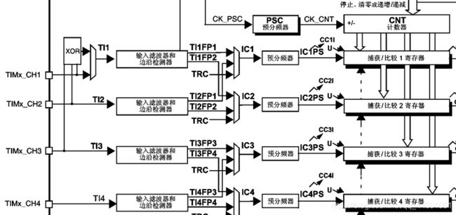
输入捕获可以对输入的信号的上升沿,下降沿或者双边沿进行捕获,常用来测量输入信号的脉宽和频率
输入捕获应用
输入捕获模式可以用来测量频率或者电平持续的时间
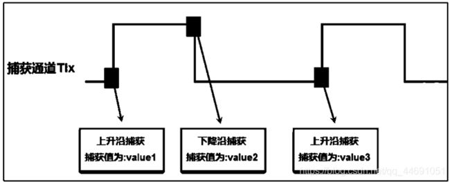
输入捕获测电平持续的时间
输入捕获测量低电平举例

每次溢出中断里面+1
二、例程代码
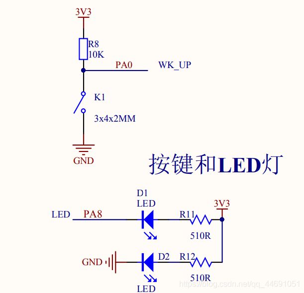
利用定时器2的输入捕获功能测量按下KEY1键后低电平持续的时间

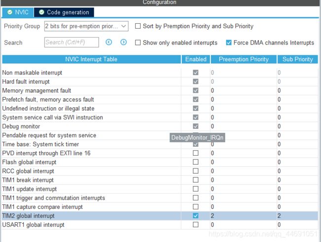
中断配置
关键功能函数说明
代码如下(示例):
__HAL_TIM_DISABLE(&htim2);					//关闭定时器

__HAL_TIM_SET_COUNTER(&htim2,0);				//设置计数器的值为0
TIM_RESET_CAPTUREPOLARITY(&htim2,TIM_CHANNEL_1); 	//清除原来的设置
TIM_SET_CAPTUREPOLARITY(&htim2,TIM_CHANNEL_1, TIM_INPUTCHANNELPOLARITY_RISING);
								//设置为上升沿捕获
__HAL_TIM_ENABLE(&htim2);       				 //使能定时器
main.c
/* USER CODE BEGIN Header */
/**
  ******************************************************************************
  * @file           : main.c
  * @brief          : Main program body
  ******************************************************************************
  * @attention
  *
  * © Copyright (c) 2020 STMicroelectronics.
  * All rights reserved.
  *
  * This software component is licensed by ST under BSD 3-Clause license,
  * the "License"; You may not use this file except in compliance with the
  * License. You may obtain a copy of the License at:
  *                        opensource.org/licenses/BSD-3-Clause
  *
  ******************************************************************************
  */
/* USER CODE END Header */
/* Includes ------------------------------------------------------------------*/
#include "main.h"
#include "tim.h"
#include "usart.h"
#include "gpio.h"
#include "stdio.h"
/* Private includes ----------------------------------------------------------*/
/* USER CODE BEGIN Includes */

/* USER CODE END Includes */

/* Private typedef -----------------------------------------------------------*/
/* USER CODE BEGIN PTD */

/* USER CODE END PTD */

/* Private define ------------------------------------------------------------*/
/* USER CODE BEGIN PD */
/* USER CODE END PD */

/* Private macro -------------------------------------------------------------*/
/* USER CODE BEGIN PM */
int fputc(int ch, FILE *p)
{
	while(!(USART1->SR & (1<<7)));

	USART1->DR = ch;

	return ch;
}

/* USER CODE END PM */

/* Private variables ---------------------------------------------------------*/

/* USER CODE BEGIN PV */

/* USER CODE END PV */

/* Private function prototypes -----------------------------------------------*/
void SystemClock_Config(void);
/* USER CODE BEGIN PFP */

/* USER CODE END PFP */

/* Private user code ---------------------------------------------------------*/
/* USER CODE BEGIN 0 */
void TIM1_Set_Compare(uint32_t compare)
{
		TIM1->CCR1=compare;
}
/* USER CODE END 0 */

/**
  * @brief  The application entry point.
  * @retval int
  */
int main(void)
{
  /* USER CODE BEGIN 1 */
   int32_t compare = 0;
	 uint8_t dir = 0;
  /* USER CODE END 1 */

  /* MCU Configuration--------------------------------------------------------*/

  /* Reset of all peripherals, Initializes the Flash interface and the Systick. */
  HAL_Init();

  /* USER CODE BEGIN Init */

  /* USER CODE END Init */

  /* Configure the system clock */
  SystemClock_Config();

  /* USER CODE BEGIN SysInit */

  /* USER CODE END SysInit */

  /* Initialize all configured peripherals */
  MX_GPIO_Init();
  MX_TIM1_Init();
  MX_TIM2_Init();
  MX_USART1_UART_Init();
  /* USER CODE BEGIN 2 */
  HAL_TIM_PWM_Start(&htim1, TIM_CHANNEL_1);   //启动PWM定时器
		printf("this is tim2 cap test\n");

	 HAL_TIM_Base_Start_IT(&htim2);   //使能溢出更新中断
	 HAL_TIM_IC_Start_IT (&htim2, TIM_CHANNEL_1);

  /* USER CODE END 2 */

  /* Infinite loop */
  /* USER CODE BEGIN WHILE */
  while (1)
  {
		if(!dir)      //向上增长
		{
			compare += 10;

			if(compare>=1000)
			{
				compare = 1000-1;
				dir = 1;
			}
		}
		else           //向下增长
		{
			compare -= 10;

			if(compare<=0)
			{
				compare = 0;
				dir = 0;
			}

		}

		TIM1_Set_Compare(compare);

		HAL_Delay(20);
    /* USER CODE END WHILE */

    /* USER CODE BEGIN 3 */
  }
  /* USER CODE END 3 */
}

/**
  * @brief System Clock Configuration
  * @retval None
  */
void SystemClock_Config(void)
{
  RCC_OscInitTypeDef RCC_OscInitStruct = {0};
  RCC_ClkInitTypeDef RCC_ClkInitStruct = {0};

  /** Initializes the RCC Oscillators according to the specified parameters
  * in the RCC_OscInitTypeDef structure.
  */
  RCC_OscInitStruct.OscillatorType = RCC_OSCILLATORTYPE_HSE;
  RCC_OscInitStruct.HSEState = RCC_HSE_ON;
  RCC_OscInitStruct.HSEPredivValue = RCC_HSE_PREDIV_DIV1;
  RCC_OscInitStruct.HSIState = RCC_HSI_ON;
  RCC_OscInitStruct.PLL.PLLState = RCC_PLL_ON;
  RCC_OscInitStruct.PLL.PLLSource = RCC_PLLSOURCE_HSE;
  RCC_OscInitStruct.PLL.PLLMUL = RCC_PLL_MUL9;
  if (HAL_RCC_OscConfig(&RCC_OscInitStruct) != HAL_OK)
  {
    Error_Handler();
  }
  /** Initializes the CPU, AHB and APB buses clocks
  */
  RCC_ClkInitStruct.ClockType = RCC_CLOCKTYPE_HCLK|RCC_CLOCKTYPE_SYSCLK
                              |RCC_CLOCKTYPE_PCLK1|RCC_CLOCKTYPE_PCLK2;
  RCC_ClkInitStruct.SYSCLKSource = RCC_SYSCLKSOURCE_PLLCLK;
  RCC_ClkInitStruct.AHBCLKDivider = RCC_SYSCLK_DIV1;
  RCC_ClkInitStruct.APB1CLKDivider = RCC_HCLK_DIV2;
  RCC_ClkInitStruct.APB2CLKDivider = RCC_HCLK_DIV1;

  if (HAL_RCC_ClockConfig(&RCC_ClkInitStruct, FLASH_LATENCY_2) != HAL_OK)
  {
    Error_Handler();
  }
}

/* USER CODE BEGIN 4 */

/* USER CODE END 4 */

/**
  * @brief  This function is executed in case of error occurrence.
  * @retval None
  */
void Error_Handler(void)
{
  /* USER CODE BEGIN Error_Handler_Debug */
  /* User can add his own implementation to report the HAL error return state */
  __disable_irq();
  while (1)
  {
  }
  /* USER CODE END Error_Handler_Debug */
}

#ifdef  USE_FULL_ASSERT
/**
  * @brief  Reports the name of the source file and the source line number
  *         where the assert_param error has occurred.
  * @param  file: pointer to the source file name
  * @param  line: assert_param error line source number
  * @retval None
  */
void assert_failed(uint8_t *file, uint32_t line)
{
  /* USER CODE BEGIN 6 */
  /* User can add his own implementation to report the file name and line number,
     ex: printf("Wrong parameters value: file %s on line %d\r\n", file, line) */
  /* USER CODE END 6 */
}
#endif /* USE_FULL_ASSERT */

/************************ (C) COPYRIGHT STMicroelectronics *****END OF FILE****/
tim.c
/**
******************************************************************************
* File Name : TIM.c
* Description : This file provides code for the configuration
* of the TIM instances.
******************************************************************************
** This notice applies to any and all portions of this file
* that are not between comment pairs USER CODE BEGIN and
* USER CODE END. Other portions of this file, whether
* inserted by the user or by software development tools
* are owned by their respective copyright owners.
*
* COPYRIGHT(c) 2018 STMicroelectronics
*
* Redistribution and use in source and binary forms, with or without modification,
* are permitted provided that the following conditions are met:
* 1. Redistributions of source code must retain the above copyright notice,
* this list of conditions and the following disclaimer.
* 2. Redistributions in binary form must reproduce the above copyright notice,
* this list of conditions and the following disclaimer in the documentation
* and/or other materials provided with the distribution.
* 3. Neither the name of STMicroelectronics nor the names of its contributors
* may be used to endorse or promote products derived from this software
* without specific prior written permission.
*
* THIS SOFTWARE IS PROVIDED BY THE COPYRIGHT HOLDERS AND CONTRIBUTORS "AS IS"
* AND ANY EXPRESS OR IMPLIED WARRANTIES, INCLUDING, BUT NOT LIMITED TO, THE
* IMPLIED WARRANTIES OF MERCHANTABILITY AND FITNESS FOR A PARTICULAR PURPOSE ARE
* DISCLAIMED. IN NO EVENT SHALL THE COPYRIGHT HOLDER OR CONTRIBUTORS BE LIABLE
* FOR ANY DIRECT, INDIRECT, INCIDENTAL, SPECIAL, EXEMPLARY, OR CONSEQUENTIAL
* DAMAGES (INCLUDING, BUT NOT LIMITED TO, PROCUREMENT OF SUBSTITUTE GOODS OR
* SERVICES; LOSS OF USE, DATA, OR PROFITS; OR BUSINESS INTERRUPTION) HOWEVER
* CAUSED AND ON ANY THEORY OF LIABILITY, WHETHER IN CONTRACT, STRICT LIABILITY,
* OR TORT (INCLUDING NEGLIGENCE OR OTHERWISE) ARISING IN ANY WAY OUT OF THE USE
* OF THIS SOFTWARE, EVEN IF ADVISED OF THE POSSIBILITY OF SUCH DAMAGE.
*
******************************************************************************
*/
/* Includes ------------------------------------------------------------------*/
#include "tim.h"
#include "gpio.h"
/* USER CODE BEGIN 0 */
/* USER CODE END 0 */
TIM_HandleTypeDef htim2;
/* TIM2 init function */
void MX_TIM2_Init(void)
{
TIM_ClockConfigTypeDef sClockSourceConfig;
TIM_MasterConfigTypeDef sMasterConfig;
TIM_IC_InitTypeDef sConfigIC;
htim2.Instance = TIM2;
htim2.Init.Prescaler = 84-1;
htim2.Init.CounterMode = TIM_COUNTERMODE_UP;
htim2.Init.Period = 1000000-1;
htim2.Init.ClockDivision = TIM_CLOCKDIVISION_DIV1;
if (HAL_TIM_Base_Init(&htim2) != HAL_OK)
{
_Error_Handler(__FILE__, __LINE__);
}
sClockSourceConfig.ClockSource = TIM_CLOCKSOURCE_INTERNAL;
if (HAL_TIM_ConfigClockSource(&htim2, &sClockSourceConfig) != HAL_OK)
{
_Error_Handler(__FILE__, __LINE__);
}
if (HAL_TIM_IC_Init(&htim2) != HAL_OK)
{
_Error_Handler(__FILE__, __LINE__);
}
sMasterConfig.MasterOutputTrigger = TIM_TRGO_RESET;
sMasterConfig.MasterSlaveMode = TIM_MASTERSLAVEMODE_DISABLE;
if (HAL_TIMEx_MasterConfigSynchronization(&htim2, &sMasterConfig) != HAL_OK)
{
_Error_Handler(__FILE__, __LINE__);
}
sConfigIC.ICPolarity = TIM_INPUTCHANNELPOLARITY_FALLING;
sConfigIC.ICSelection = TIM_ICSELECTION_DIRECTTI;
sConfigIC.ICPrescaler = TIM_ICPSC_DIV1;
sConfigIC.ICFilter = 0;
if (HAL_TIM_IC_ConfigChannel(&htim2, &sConfigIC, TIM_CHANNEL_1) != HAL_OK)
{
_Error_Handler(__FILE__, __LINE__);
}
}
void HAL_TIM_Base_MspInit(TIM_HandleTypeDef* tim_baseHandle)
{
GPIO_InitTypeDef GPIO_InitStruct;
if(tim_baseHandle->Instance==TIM2)
{
/* USER CODE BEGIN TIM2_MspInit 0 */
/* USER CODE END TIM2_MspInit 0 */
/* TIM2 clock enable */
__HAL_RCC_TIM2_CLK_ENABLE();
/**TIM2 GPIO Configuration
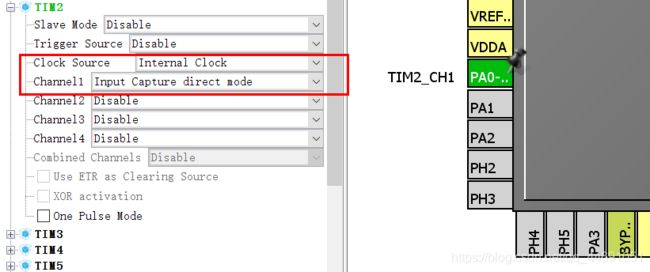
PA0-WKUP ------> TIM2_CH1
*/
GPIO_InitStruct.Pin = GPIO_PIN_0;
GPIO_InitStruct.Mode = GPIO_MODE_AF_PP;
GPIO_InitStruct.Pull = GPIO_NOPULL;
GPIO_InitStruct.Speed = GPIO_SPEED_FREQ_LOW;
GPIO_InitStruct.Alternate = GPIO_AF1_TIM2;
HAL_GPIO_Init(GPIOA, &GPIO_InitStruct);
/* TIM2 interrupt Init */
HAL_NVIC_SetPriority(TIM2_IRQn, 2, 2);
HAL_NVIC_EnableIRQ(TIM2_IRQn);
/* USER CODE BEGIN TIM2_MspInit 1 */
/* USER CODE END TIM2_MspInit 1 */
}
}
void HAL_TIM_Base_MspDeInit(TIM_HandleTypeDef* tim_baseHandle)
{
if(tim_baseHandle->Instance==TIM2)
{
/* USER CODE BEGIN TIM2_MspDeInit 0 */
/* USER CODE END TIM2_MspDeInit 0 */
/* Peripheral clock disable */
__HAL_RCC_TIM2_CLK_DISABLE();
/**TIM2 GPIO Configuration
PA0-WKUP ------> TIM2_CH1
*/
HAL_GPIO_DeInit(GPIOA, GPIO_PIN_0);
/* TIM2 interrupt Deinit */
HAL_NVIC_DisableIRQ(TIM2_IRQn);
/* USER CODE BEGIN TIM2_MspDeInit 1 */
/* USER CODE END TIM2_MspDeInit 1 */
}
}
/* USER CODE BEGIN 1 */
uint8_t fall_flag = 0; //下降沿捕获标记位
uint32_t cap_value = 0;
void HAL_TIM_PeriodElapsedCallback(TIM_HandleTypeDef *htim)
{
if(htim->Instance == TIM2)
{
if(fall_flag)
{
cap_value += 1000000; //每次溢出做一个加ARR的记录
printf("update int \n");
}
}
}
void HAL_TIM_IC_CaptureCallback(TIM_HandleTypeDef *htim)
{
if(htim->Instance == TIM2)
{
if(!fall_flag) //当前捕获到的是下降沿
{
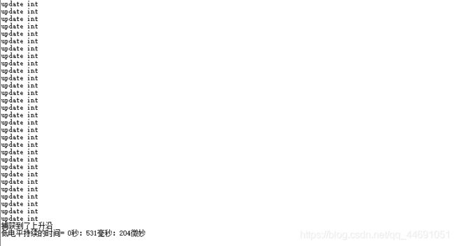
printf("捕获到了下降沿\n");
HAL_Delay(20); //延时20ms消抖
if( HAL_GPIO_ReadPin(GPIOA, GPIO_PIN_0) == GPIO_PIN_RESET)
{
fall_flag = 1;
__HAL_TIM_DISABLE(htim); //关闭定时器
__HAL_TIM_SET_COUNTER(htim,0); //设置计数器的值为0
TIM_RESET_CAPTUREPOLARITY(htim,TIM_CHANNEL_1); //清除原来的设置
TIM_SET_CAPTUREPOLARITY(htim,TIM_CHANNEL_1, TIM_INPUTCHANNELPOLARITY_RISING); //设置为上升沿捕获
__HAL_TIM_ENABLE(htim); //使能定时器
}
}
else //当前捕获到的是上升沿,本次捕获结束
{
printf("捕获到了上升沿\n");
fall_flag = 0;
//最终的时间= 溢出的时间 + 两次计数差值 + 延时抖动的时间
cap_value = cap_value + HAL_TIM_ReadCapturedValue(htim, TIM_CHANNEL_1) + 20000 ;
printf("低电平持续的时间= %d秒:%d毫秒:%d微妙\n",cap_value/1000000,cap_value%1000000/1000,cap_value%1000);
cap_value = 0;
__HAL_TIM_DISABLE(htim); //关闭定时器
TIM_RESET_CAPTUREPOLARITY(htim,TIM_CHANNEL_1); //清除原来的设置
TIM_SET_CAPTUREPOLARITY(htim,TIM_CHANNEL_1, TIM_INPUTCHANNELPOLARITY_FALLING); //设置为下降沿捕获
__HAL_TIM_ENABLE(htim); //使能定时器
HAL_Delay(20);
}
}
}
/* USER CODE END 1 */
/**
* @}
*/
/**
* @}
*/
/************************ (C) COPYRIGHT STMicroelectronics *****END OF FILE****/
现象如下:
按住按键抬起按键会记录按下多长时间并从串口打印出来。

时间计算挺准的,至于电机测速无非也是这个原理计算一定时间内高电平或低电平次数,一圈多少个高低电平,结合轮子形状,知道距离,距离除以时间即是速度。