综合组网实例配置 双出口双墙主备+三层核心VRRP+MSTP+NAT+NAT SERVER+AC+IPsec+广域网PPPOE+专线
一、 组网需求
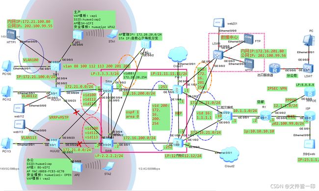
企业的两台FW的业务接口都工作在三层,使用路由模式进行部署,上下行分别连接交换机。上行交换机连接路由器,下行连接核心交换机。路由器连接二个运营商的接入点,运营商其一为企业提供专线业务,其分配的IP地址为202.100.99.55~56(用做内部web服务映射)。运营商其二为企业提供pppoe拨号。专线业务主要用于企业业务系统为外部提供访问,员工上网使用pppoe线路。通过在路由器上部署策略路由以实现业务和上网流量的分流。
现在希望两台FW以主备备份方式工作。正常情况下,流量通过FW-1转发。当FW-1出现故障时,流量通过FW-2转发,保证业务不中断。内网核心网络通过VRRP+MSTP的组网方式将二台5700核心交换机与汇聚交换机建立具有冗余、负载的高可靠的网络。同时AC控制器也通过vrrp的形式与二台核心交换机建立连接,为内网用户提供无线访问业务。数据中心也采用VRRP的形式与二台防火墙建立连接,并且都放置在DMZ区域。在边界出口路由器上通过配置IP SEC VPN与分部网络中心建立连接,实现集团内资源共享和业务访问。在边界出口路由器上配置NAT SERVER将内网VLAN 100中的http服务和DMZ区域VLAN 201中的ftp服务发布到外网,并配置Easy-IP允许内网100和112的用户可以上网,113网段的用户不能上网(后期更改为100和201走专线,112和113走pppoe线路上网)。为了实现内网用户可以通过公网IP访问内网的http和ftp服务,在路由器上配置域内NAT。
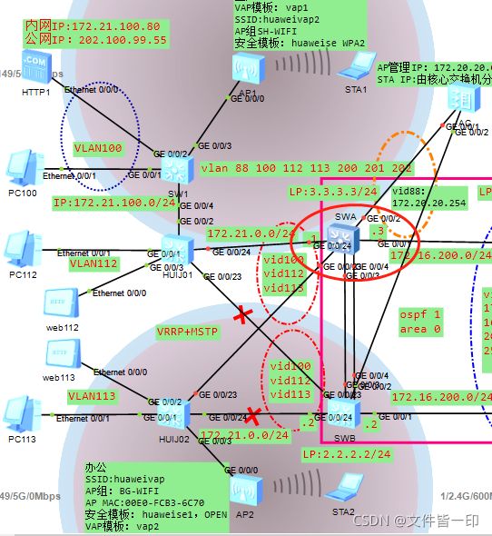
二、网络拓扑
其他说明:IP SEC VPN未完成。
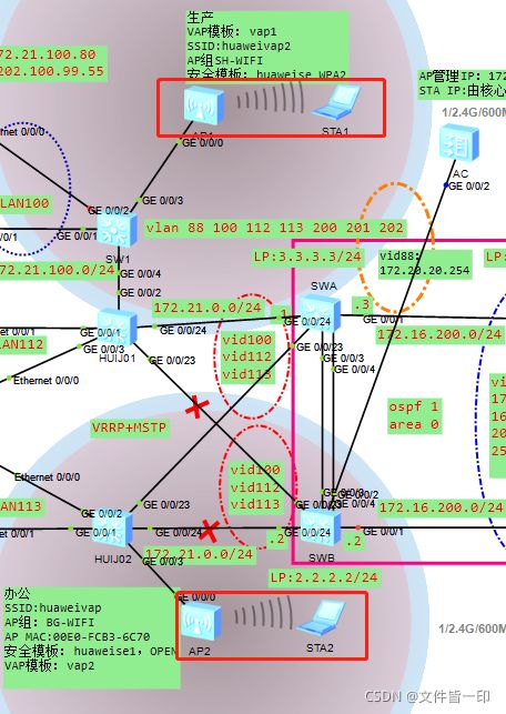
三、AC无线网络规划
3.1 常规AC组网方式
(1)单节点(无冗余)
(2)双链路双机热备(AP同时与主备AC建立CAPWAP隧道,也需要通过HSB通道同步业务信息)
(3)VRRP双机热备(AC之间通过HSB同步业务信息和用户信息)
(4)特殊情况就是我这个网络拓扑,因为现网只有一个AC,且核心又做了VRRP,只能采用这种组网方式规划AC。(其实现在基本都在采用交换机虚拟机技术,VRRP在核心层的组网还是少了)
3.2 网络规划
(1)AC组网方式为三层组网,直接转发模式。
(2)AC:172.20.20.253,SWA:172.20.20.1,SWB:172.20.20.2。业务网段暂时与有线网段一样,分别为VALN100,VALN112和VALN113。
(3)VRRP组VID:88,虚拟网关地址为:172.20.20.254。SWA为主,SWB为备。
问题:(应该是ensp的bug,真机或者没有这个问题)
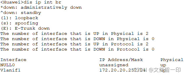
默认情况下AC上STP功能是禁用的。在主SWA正常的情况下,AC上开启stp enable对无线业务无影响(如果不开启stp服务,网络会出现环路),AP能与AC建立CAPWAP隧道。但是假如主SWA的G0/0/2口出现故障或SWA与AC之间的链路出现故障,或者是SWA出现当机后。SWA和SWB之间的主备VRRP组能正常切换,但是当SWB成为主后,AP始终无法上线,从AP或SWB上无法ping通AC的172.20.20.253。同样从AC上无法ping通VRRP虚拟网关172.20.20.254。
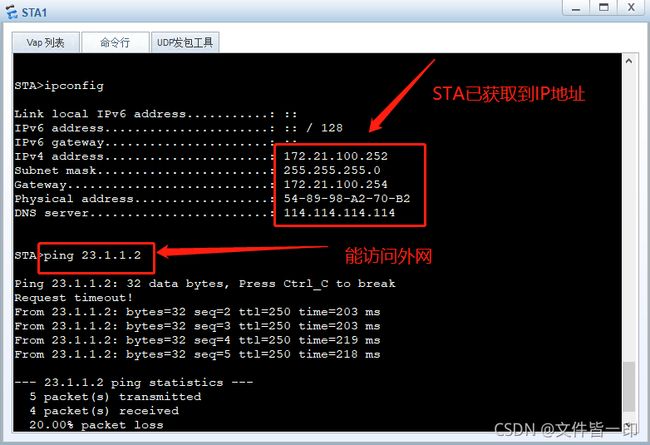
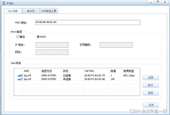
此种情况下,如果在AC上执行undo stp enable后(或者全局stp enable,然后在G0/0/2接口下执行stp disable),AP能与AC建立CAPWAP隧道,无线网络恢复正常,STA也能搜索到ssid并能连接上,且访问外网正常。如下:
四、IP SEC VPN规划
未完成
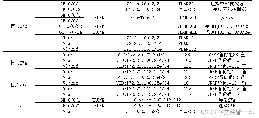
五、IP地址规划
六、配置思路
6.1 防火墙部署位置
防火墙上连路由器,下连三层交换机。为了解决路由器接口不足问题,在防火墙和路由器之间接入一个二层汇聚交换机。上行VRRP虚拟网关地址 1.1.1.1/24 ,采用双链路双网关确保出口正常使用。下行VRRP虚拟网关地址 172.16.200.254/24,采用双链路双网关确保核心网络正常使用。
6.2 配置防火墙主备
二台防火墙做主备备份,其中FW-1为主,FW-2为备。二台防火墙通过心跳线监测VRRP的状态和故障切换。FW-1上配置接口track,一旦发生接口故障或链路故障,Master和Backup角色将进行互换。FW-1上配置角色抢占功能(hrp preempt delay 20),当FW-1接口或链路故障恢复正常后,将在20秒后进行Master角色抢占。
6.3 配置安全策略
在主FW-1上创建二条策略(会自动同步到FW-2上)。①允许trust区域到untrust区域的流量访问 ②允许hrp区域hrp区域的流量访问,此策略主要是为了让二台防火墙之间的vrrp心跳报文能正常传输。③允许从外网访问企业内部的web服务,指定外网可以访问目标服务器172.21.100.80和172.16.201.80。
6.4 策略路由
规划核心业务系统(VLAN100 VLAN201网段)从专线出去,在R1上做策略路由并将配置下一跳的地址为202.100.99.2。普通上网流量走PPPOE拨号线路。在R1上配置一条默认路由,下一跳为Dialer1并调用NQA,同时配置一条到202.100.99.2的默认路由,优先级为65。
6.5 NAT策略
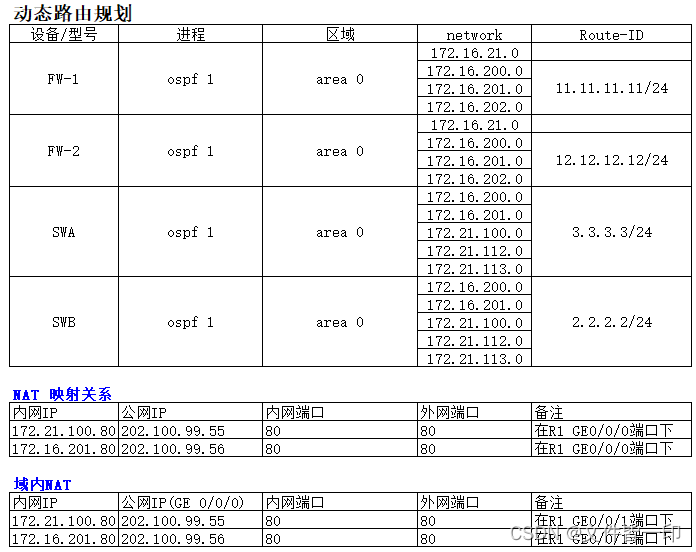
在R1上做NAT Server上。同时为了能让内网用户通过公网IP访问HTTP服务器,在GE 0/0/1内网口做域内NAT+NAT Server(双向NAT),服务器映射关系如下:
FW-1配置
#配置设备名称
sysname FW1
#配置HRP
hrp enable
hrp interface GigabitEthernet1/0/6 remote 172.16.202.2
hrp mirror session enable
hrp adjust ospf-cost enable
hrp standby config enable
hrp track interface GigabitEthernet1/0/0
hrp track interface GigabitEthernet1/0/2
hrp track ip-link ppp0e
#配置防火墙安全防护
firewall defend time-stamp enable
firewall defend route-record enable
firewall defend source-route enable
firewall defend winnuke enable
firewall defend fraggle enable
firewall defend ping-of-death enable
firewall defend smurf enable
firewall defend land enable
firewall defend action discard
#配置ip-link,监测上联口线路健康状态
ip-link check enable
ip-link name ppp0e
destination 1.1.1.10 mode icmp
#配置Trust区域 接口IP和VRRP,允许ping服务
interface GigabitEthernet1/0/0
undo shutdown
ip address 172.16.200.253 255.255.255.0
vrrp vrid 200 virtual-ip 172.16.200.254 active
service-manage ping permit
#配置Untrust区域 接口IP和VRRP,允许ping服务
interface GigabitEthernet1/0/2
shutdown
ip address 172.16.21.1 255.255.255.0
vrrp vrid 16 virtual-ip 1.1.1.1 255.255.255.0 active
service-manage ping permit
#配置心跳口IP,允许ping服务
interface GigabitEthernet1/0/6
undo shutdown
ip address 172.16.202.1 255.255.255.0
service-manage ping permit
#配置环回口,用于ospf route-id
interface LoopBack1
ip address 11.11.11.11 255.255.255.0
#将接口加入trust区域
firewall zone trust
set priority 85
add interface GigabitEthernet0/0/0
add interface GigabitEthernet1/0/0
#将接口加入untrust区域
firewall zone untrust
set priority 5
add interface GigabitEthernet1/0/2
#将接口加入dmz区域
firewall zone dmz
set priority 50
add interface GigabitEthernet1/0/1
#创建hrp区域,优先级为4(此值可随意设置) ,将接口加入该区域
firewall zone name hrp id 4
add interface GigabitEthernet1/0/6
#配置OSPF动态路由,将直接路由发布到网络中
ospf 1 router-id 11.11.11.11
default-route-advertise
area 0.0.0.0
network 172.16.21.0 0.0.0.255
network 172.16.200.0 0.0.0.255
network 172.16.201.0 0.0.0.255
network 172.16.202.0 0.0.0.255
#配置默认静态路由,下一跳是1.1.1.10,并调用ip-link监测线路
ip route-static 0.0.0.0 0.0.0.0 1.1.1.10 track ip-link ppp0e
#配置安全策略
security-policy
default action permit
rule name hrp2hrp
source-zone hrp
destination-zone hrp
action permit
rule name trust2untrust
source-zone trust
destination-zone untrust
action permit
rule name untrust2trust
source-zone untrust
destination-zone trust dmz
destination-address 172.21.100.80
destination-address 172.16.201.80
action permit
#
FW-2配置
#
sysname FW2
#
hrp enable
hrp interface GigabitEthernet1/0/6 remote 172.16.202.1
hrp mirror session enable
hrp adjust ospf-cost enable
hrp standby config enable
#
firewall defend time-stamp enable
firewall defend route-record enable
firewall defend source-route enable
firewall defend winnuke enable
firewall defend fraggle enable
firewall defend ping-of-death enable
firewall defend smurf enable
firewall defend land enable
firewall defend action discard
#
interface GigabitEthernet1/0/0
undo shutdown
ip address 172.16.200.252 255.255.255.0
vrrp vrid 200 virtual-ip 172.16.200.254 standby
service-manage ping permit
#
interface GigabitEthernet1/0/1
undo shutdown
ip address 172.16.201.252 255.255.255.0
vrrp vrid 201 virtual-ip 172.16.201.254 standby
service-manage ping permit
#
interface GigabitEthernet1/0/2
undo shutdown
ip address 172.16.21.2 255.255.255.0
vrrp vrid 16 virtual-ip 1.1.1.1 255.255.255.0 standby
service-manage ping permit
#
interface GigabitEthernet1/0/6
undo shutdown
ip address 172.16.202.2 255.255.255.0
#
interface Virtual-if0
#
interface LoopBack1
ip address 12.12.12.12 255.255.255.0
#
firewall zone trust
set priority 85
add interface GigabitEthernet0/0/0
add interface GigabitEthernet1/0/0
#
firewall zone untrust
set priority 5
add interface GigabitEthernet1/0/2
#将接口加入dmz区域
firewall zone dmz
set priority 50
add interface GigabitEthernet1/0/1
#
firewall zone name hrp id 4
add interface GigabitEthernet1/0/6
#
ospf 1 router-id 12.12.12.12
default-route-advertise
area 0.0.0.0
network 172.16.21.0 0.0.0.255
network 172.16.200.0 0.0.0.255
network 172.16.201.0 0.0.0.255
network 172.16.202.0 0.0.0.255
#配置默认静态路由,下一跳是1.1.1.10,备用墙不需要调用IP-LINK。
ip route-static 0.0.0.0 0.0.0.0 1.1.1.10
#
security-policy
default action permit
rule name hrp2hrp
source-zone hrp
destination-zone hrp
action permit
rule name trust2untrust
source-zone trust
destination-zone untrust
action permit
rule name untrust2trust
source-zone untrust
destination-zone trust dmz
destination-address 172.21.100.80
destination-address 172.16.201.80
action permit
#
二层交换机配置
#
sysname Huawei
#
undo info-center enable
#创建VLAN
vlan batch 10 16
#配置VLAN10 IP地址
interface Vlanif10
ip address 10.1.1.1 255.255.255.0
#配置VLAN16 IP地址
interface Vlanif16
ip address 1.1.1.10 255.255.255.0
#将接口加入VLAN 10
interface GigabitEthernet0/0/1
port link-type access
port default vlan 10
#将接口加入VLAN 16
interface GigabitEthernet0/0/2
port link-type access
port default vlan 16
#将接口加入VLAN 16
interface GigabitEthernet0/0/3
port link-type access
port default vlan 16
#配置静态路由,默认路由下一跳地址为路由品的内网接口。其他二个网段的下一跳为VRRP备份组16的虚拟IP地址
ip route-static 0.0.0.0 0.0.0.0 10.1.1.2
ip route-static 172.16.0.0 255.255.0.0 1.1.1.1
ip route-static 172.21.0.0 255.255.0.0 1.1.1.1
#
R1路由器配置
#
sysname R1
#配置ACL
#
acl number 2000 ----------------定义用于进行策略路由的网段。即HTTP服务和数据中心的FTP服务器网段。
description server-PBR
rule 15 permit source 172.16.201.0 0.0.0.255
rule 20 permit source 172.21.100.0 0.0.0.255
acl number 2001 ----------------定义允许通过PPPOE拨号线路上网的网段
description permit-pcnat-pppoe
rule 5 permit source 172.21.112.0 0.0.0.255
rule 10 permit source 172.21.113.0 0.0.0.255
acl number 2002 ----------------用于内网做源NAT的网段,即所有内网的网段都可以通过公网IP地址访问HTTP服务器和FTP服务器
description source-NAT
rule 5 permit source 172.21.100.0 0.0.0.255
rule 10 permit source 172.21.112.0 0.0.0.255
rule 15 permit source 172.21.113.0 0.0.0.255
rule 20 permit source 172.16.201.0 0.0.0.255
#
acl number 3002 ----------------定义从172.21.100.80和172.16.201.80到内网口的IP访问的流量不做PBR转换。从而保证内网用户在能通过公网IP访问这二台服务器。
description NO-PBR NAT
rule 5 permit ip source 10.1.1.2 0 destination 172.16.201.80 0
rule 6 permit ip source 10.1.1.2 0 destination 172.21.100.80 0
rule 25 permit ip source 172.16.201.80 0 destination 10.1.1.2 0
rule 27 permit ip source 172.21.100.80 0 destination 10.1.1.2 0
##配置NAT 地址池表
nat address-group 1 202.100.99.55 202.100.99.56
#在外网口配置Easy-IP和NAT SERVER
interface GigabitEthernet0/0/0
description ISP
ip address 202.100.99.1 255.255.255.0
nat server protocol tcp global 202.100.99.55 www inside 172.21.100.80 www
nat server protocol tcp global 202.100.99.56 www inside 172.16.201.80 www
nat outbound 2000
#在R1 G0/0/1内网口配置Easy-IP和NAT SERVER
#
interface GigabitEthernet0/0/1
description SW2
ip address 10.1.1.2 255.255.255.0
traffic-policy server2-policy inbound------------应用流策略,方向为inbound
nat server protocol tcp global 202.100.99.55 www inside 172.21.100.80 www
nat server protocol tcp global 202.100.99.56 www inside 172.16.201.80 www
nat outbound 2002---------------------------应用acl,允许内网做nat转化。
#
#配置策略路由
#
traffic classifier server-policy operator or
if-match acl 2000
traffic classifier no-policy operator or
if-match acl 3002
#
traffic behavior server-policy-b1
redirect ip-nexthop 202.100.99.2 track nqa test 202----------指定下一跳的地址为202.100.99.2,并调用NQA。
traffic behavior no-policy-b1-----------默认动作是不执行策略转换
#
traffic policy server2-policy
classifier no-policy behavior no-policy-b1-------不做策略路由转换的放在前面。调用流分类、流行为。
classifier server-policy behavior server-policy-b1-------做策略路由转换的放在最后面。调用流分类、流行为。
#
#配置连接PPPOE的接口,调用拨号。
#
interface GigabitEthernet0/0/2
pppoe-client dial-bundle-number 1
description PPPOE-SERVER
#
#配置PPPOE客户端
dialer-rule
dialer-rule 1 ip permit
interface Dialer1
link-protocol ppp
ppp chap user test
ppp chap password cipher %$%$6VUfY9bEj7QM@BX#Y>72,7S#%$%$
ip address ppp-negotiate
dialer user test
dialer bundle 1
dialer-group 1
nat outbound 2001
#配置NQA
nqa test-instance test 202
test-type icmp
destination-address ipv4 202.100.99.2
frequency 10
interval seconds 5
probe-count 2
start now
nqa test-instance test dialer
test-type icmp
destination-address ipv4 8.8.8.8
frequency 20-------这个时间要比interval和probe-count的高。
interval seconds 5
probe-count 2
source-interface Dialer1-------指定源接口为Dialer1,不能写接口!
#
#配置环回口IP
interface LoopBack1
ip address 10.10.10.10 255.255.255.0
#配置静态路由
ip route-static 0.0.0.0 0.0.0.0 Dialer1 track nqa test dialer
ip route-static 0.0.0.0 0.0.0.0 202.100.99.2 preference 65
ip route-static 1.1.1.0 255.255.255.0 10.1.1.1
ip route-static 172.16.0.0 255.255.0.0 10.1.1.1
ip route-static 172.21.0.0 255.255.0.0 10.1.1.1
#
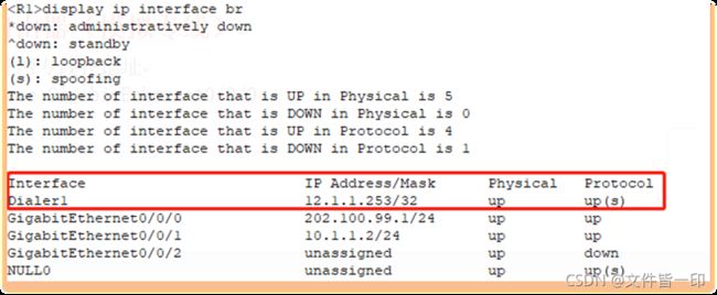
验证:R1从PPPOE服务器获取到IP地址
实战分享:华为AR1220配置 PPPOE拨号
#创建拨号规则,名称为1,允许ip流量通过
dialer-rule
 dialer-rule 1 ip permit
#创建拨号口Dialer 1
interface Dialer1
 link-protocol ppp
 ppp chap user [email protected]
 ppp chap password cipher %^%#'&:3('MiOWZ/4W:*`IGY)m:I8{Y[91^Y0HJixo,2%^%#
 ppp ipcp dns admit-any
 ppp ipcp dns request
 tcp adjust-mss 1200
 ip address ppp-negotiate
 dialer user [email protected]
 dialer bundle 1
 dialer number 1 autodial
 dialer-group 1
 nat outbound 3399
 ip accounting input-packets    #统计入流量数据所包
 ip accounting output-packets   #统计出流量数据所包
#将拨号Dialer 1应用到WAN口
interface GigabitEthernet0/0/9
 pppoe-client dial-bundle-number 1
 description connect_PPPOE
#创建acl,允许内网用户上网
acl number 3399
 rule 5 permit ip
#配置静态路由
ip route-static 0.0.0.0 0.0.0.0 Dialer1
#调整负载均衡算法,配置基于源IP地址方式进行负载分担
ip load-balance hash src-ip
#启用http服务和修改默认端口,并将内网口配置为管理地址
 http secure-server port 8443
 http secure-server ssl-policy default_policy
 http server enable
 http secure-server enable
 http server permit interface GigabitEthernet0/0/0
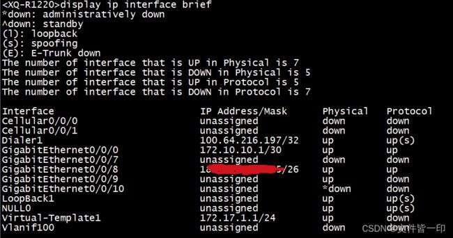
(2)display ip interface brief查看获取到的动态公网IP
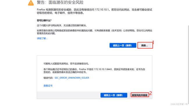
(3)Web管理登录
输入用户名和密码登录
查看接口配置
电信专线
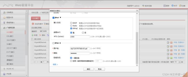
查看PPPOE接口详情
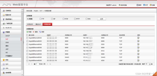
源NAT(外网访问)
目的NAT(内部服务发布到外网)
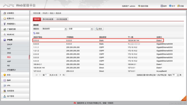
查看路由表
实战分享:AR配置智能选路(策略路由)
1.创建acl
#
acl name dianxin 3001
 rule 5 permit ip source 192.168.10.0 0.0.0.255
 rule 10 permit ip source 192.168.100.0 0.0.0.255
 rule 15 permit ip source 172.10.10.0 0.0.0.255
acl name pppoe 3002
 rule 5 permit ip source 192.168.88.0 0.0.0.255
 rule 10 permit ip source 192.168.87.0 0.0.0.255
acl number 3388
 rule 15 permit ip source 192.168.9.0 0.0.0.255 destination 172.10.10.1 0
 rule 16 permit ip source 192.168.10.0 0.0.0.255 destination 172.10.10.1 0
 rule 17 permit ip source 172.10.10.1 0 destination 192.168.10.0 0.0.0.255
 rule 18 permit ip source 172.10.10.1 0 destination 192.168.9.0 0.0.0.255
acl number 3399
 rule 5 permit ip
#
2.创建流分类   //将acl与流行为进行绑定
#
traffic classifier 10.0
 if-match acl ip10.0
traffic classifier tc88
 if-match acl 3002
traffic classifier tc1
 if-match acl 3388
traffic classifier tc10
 if-match acl 3001
#
3.创建流行为   //指定符合acl规则的数据下一跳出口地址
#
traffic behavior tb88   //创建流行为tb88,指定下一跳地址为Dialer1,并绑定nqa探测。
 redirect interface Dialer1 track nqa test adsl
traffic behavior 10.0
 statistic enable    //启用流量统计功能
 car cir 16384 pir 65536 cbs 32768 pbs 65536 mode color-blind green pass yellow pass red discard  //在流行为中配置限速功能,cir限速16384kbps/8=2028Kbps=2M,pir峰值最大65536kbps/8=8192Kbps=8M。
traffic behavior tb1   //创建流行为tb1
traffic behavior tb10   //创建流行为tb10,指定下一跳地址为专线对端公网IP地址,并绑定nqa探测。
 redirect ip-nexthop 183.63.212.xxx track nqa test dianxin
#
4.创建流策略    //将流分类和流行为进行绑定
#
traffic policy tp1
 classifier tc1 behavior tb1
traffic policy tp10
 classifier tc10 behavior tb10
traffic policy ip10.0
 classifier 10.0 behavior 10.0
traffic policy znsl
 classifier tc1 behavior tb1    //将不执行的数据放在流策略的最前面
 classifier tc10 behavior tb10
 classifier tc88 behavior tb88
#
5.在AR路由器的内网接口上应用流策略znsl
#
interface GigabitEthernet0/0/0
 undo portswitch
 description connect_LAN
 ip address 172.10.10.1 255.255.255.252
 nat server protocol tcp global interface GigabitEthernet 0/0/8 9999 inside 192.168.10.31 9999
 nat server protocol tcp global interface GigabitEthernet 0/0/8 8899 inside 192.168.10.35 8899
 nat outbound 3388
 traffic-policy znsl inbound
 ip accounting input-packets   //启用接口流量统计
 ip accounting output-packets  //启用接口流量统计
#
6.创建nqa探测
#
nqa test-instance test adsl
 test-type icmp
 destination-address ipv4 114.114.114.114
 frequency 20
 interval seconds 5
 probe-count 2
 source-interface Dialer1
 start now
nqa test-instance test dianxin
 test-type icmp
 destination-address ipv4 183.63.212.xxx
 source-address ipv4 183.63.212.xxx
 frequency 20
 interval seconds 5
 probe-count 2
 start now
#
7.在默认路由中绑定nqa
#
ip route-static 0.0.0.0 0.0.0.0 183.63.212.xxx track nqa test dianxin
ip route-static 0.0.0.0 0.0.0.0 Dialer1 track nqa test adsl
#
ISP路由器(模拟专线)
#配置外网专线IP地址
interface GigabitEthernet0/0/0
ip address 202.100.99.2 255.255.255.0
#配置
interface GigabitEthernet0/0/1
ip address 23.1.1.1 255.255.255.0
#配置环回口IP地址
interface LoopBack1
ip address 123.1.1.10 255.255.255.0
#配置静态路由
ip route-static 0.0.0.0 0.0.0.0 202.100.99.1
#
PPPOE路由器
#配置名称
sysname pppoe-server
#为pppoe客户端创建地址池,指定获取的IP地址范围
ip pool server
gateway-list 12.1.1.254
network 12.1.1.0 mask 255.255.255.0
dns-list 8.8.8.8 12.1.1.254
#创建虚拟接口模板,配置ppp认证模式为chap,远端地址服务IP为12.1.1.254
interface Virtual-Template1
ppp authentication-mode chap
remote address pool server-------指定远程地址池服务名称,为server。
ip address 12.1.1.254 255.255.255.0 ---------配置虚拟接口模板IP地址
#配置与远端路由器客户端连接的接口,并绑定虚拟接口模板。前面要指定pppoe-server
interface GigabitEthernet0/0/0
pppoe-server bind Virtual-Template 1
#配置环回口IP地址,用于测试。
interface LoopBack1
ip address 8.8.8.8 255.255.255.0
#配置console口认证方式为password,不需要输入用户名。如需要用户名则将authentication-mode改为aaa。
user-interface con 0
authentication-mode password //改为aaa,则调用aaa里创建的用户进行登录验证
set authentication password cipher %$%$dOl1D^1~%NiqZ\It=rO0,Sk:<%xoQi2bTVr{8z0.
TvT5Sk=,%$%$ 密码:Huawei@123
user privilege level 15-------设置用户等级,15为最高
idle-timeout 15------设置超时15后自动退出
#
user-interface vty 0 4
authentication-mode aaa
protocol inbound all
#配置aaa认证 用户名、密码和服务类型、用户级别等。(用户名:huawei,密码:Huawei@123)
aaa
local-user huawei password cipher %$%$xuM(I4Sc)W$H^QGZ-b[SfD;y%$%$
local-user huawei privilege level 15
local-user huawei service-type telnet terminal ssh
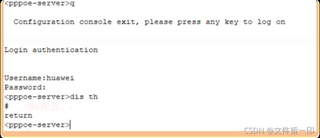
#验证console口配置aaa认证效果
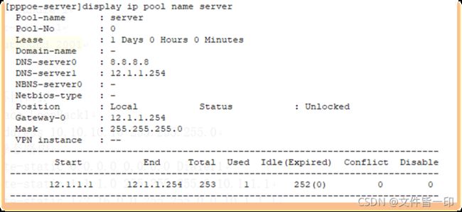
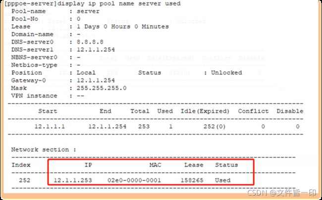
查看地址池信息
查看已从PPPOE服务器上获取到IP地址的用户
SWA配置
//在真机环境中一般需要给每个设备配置管理IP。另外,需要启用arp攻击防护,如丢弃ARP免费报文,ARP表项严格学习等。时区和时钟也要进行设置,可在核心交换机上启用ntp服务,最好为核心交换机配置外网的NTP服务器,同时其他网络设备均使用核心交换机作为源NTP服务器。
(1)arp攻击防护配置
arp learning strict
arp speed-limit source-ip 192.168.100.3 maximum 300    #对另一个分公司的汇聚交换机进行arp限速
arp anti-attack entry-check fixed-mac enable
arp gratuitous-arp send enable
(2)在用户视图下配置时间(有些设备可以在系统视图下配置)
clock datetime ?
  HH:MM:SS  Specify the time

clock datetime 14:33:30 ?
  YYYY-MM-DD  Specify the date from 2000 to 2037

clock datetime 14:33:30 2022-10-08
(3)配置时区及NTP服务
clock timezone BJ add 08:00:00
ntp-service server disable        #开启ntp服务
ntp-service ipv6 server disable   #开启ntp ipv6服务
ntp-service refclock-master 3     #主时间服务器,使用本地时钟作为NTP主时钟,层数为3,这个按需配置,也可不配置
ntp-service unicast-server 120.25.115.20  #阿里云ntp1
ntp-service unicast-server 203.107.6.88   #阿里云ntp2
——————————————————————————————————————————————————
1.给交换机命名
#
sysname SWA
#

2.创建vlan
#
vlan batch 88 100 112 to 113 200 to 201

3.配置stp实例主备,配置SWA为Instance 0主根,为Instance 1主根和为Instance 2备根
#
stp instance 0 root primary
stp instance 1 root primary
stp instance 2 root secondary
#
4.配置stp路径开销算法(现网可配可不配)
#
stp pathcost-standard legacy
#

5.配置MSTP,实例1承载VALN 100和VLAN 112的流量,实例2承载VLAN 113的流量
#
stp region-configuration
 region-name test
 instance 1 vlan 100 112
 instance 2 vlan 113
 active region-configuration
#
6.配置DHCP全局地址池表
#创建AP地址池,为AP分发管理IP。
ip pool ap
 gateway-list 172.20.20.254
 network 172.20.20.0 mask 255.255.255.0
 excluded-ip-address 172.20.20.1 172.20.20.2
 excluded-ip-address 172.20.20.253
 dns-list 114.114.114.114
 option 43 sub-option 3 ascii 199.10.10.1

7.创建VLAN100地址池
#
ip pool server
 gateway-list 172.21.100.254
 network 172.21.100.0 mask 255.255.255.0
 dns-list 114.114.114.114
#
创建VLAN112地址池
#
ip pool vlanif112
 gateway-list 172.21.112.254
 network 172.21.112.0 mask 255.255.255.0
 excluded-ip-address 172.21.112.253
 dns-list 114.114.114.114
#
创建VLAN113地址池
#
ip pool vlanif113
 gateway-list 172.21.113.254
 network 172.21.113.0 mask 255.255.255.0
 excluded-ip-address 172.21.113.253
 dns-list 114.114.114.114
#
8.配置Vlan88 IP地址和VRRP,此为与AC连接的主链路,所以优先级设置为120。
#
interface Vlanif88
 ip address 172.20.20.1 255.255.255.0
 vrrp vrid 88 virtual-ip 172.20.20.254
 vrrp vrid 88 priority 120
 vrrp vrid 88 preempt-mode timer delay 10
 vrrp vrid 88 track interface GigabitEthernet0/0/2 reduced 30
#
配置Vlanif100 IP地址和VRRP,启用DHCP全局模式
interface Vlanif100
 ip address 172.21.100.1 255.255.255.0
 vrrp vrid 100 virtual-ip 172.21.100.254
 vrrp vrid 100 priority 120
 vrrp vrid 100 track interface GigabitEthernet0/0/24 reduced 30
 vrrp vrid 100 track interface GigabitEthernet0/0/23 reduced 30
 vrrp vrid 100 track interface GigabitEthernet0/0/1 reduced 30
 dhcp select global
#
配置Vlanif112 IP地址和VRRP,启用DHCP全局模式
interface Vlanif112
 ip address 172.21.112.1 255.255.255.0
 vrrp vrid 112 virtual-ip 172.21.112.254
 vrrp vrid 112 priority 120
 vrrp vrid 112 track interface GigabitEthernet0/0/23 reduced 30
 vrrp vrid 112 track interface GigabitEthernet0/0/24 reduced 30
 vrrp vrid 112 track interface GigabitEthernet0/0/1 reduced 30
 dhcp select global
#
配置Vlanif113 IP地址和VRRP,启用DHCP全局模式
interface Vlanif113
 ip address 172.21.113.1 255.255.255.0
 vrrp vrid 113 virtual-ip 172.21.113.254
 dhcp select global
#
interface Eth-Trunk1
 port link-type trunk
 port trunk allow-pass vlan 2 to 4094
 mode lacp-static
 load-balance dst-ip
#
interface GigabitEthernet0/0/1
 port link-type access
 port default vlan 200
#允许88 100 112 113VLAN通过,这个是为了保证让AP能与AC通信。
interface GigabitEthernet0/0/2
 port link-type trunk
 port trunk allow-pass vlan 88 100 112 to 113
#

9.将GigabitEthernet0/0/3和GigabitEthernet0/0/4加入Eth-trunk1组
interface GigabitEthernet0/0/3
 eth-trunk 1
#
interface GigabitEthernet0/0/4
 eth-trunk 1
#
10.配置下级联端口
interface GigabitEthernet0/0/23
 port link-type trunk
 port trunk allow-pass vlan 88 100 112 to 113
#
interface GigabitEthernet0/0/24
 port link-type trunk
 port trunk allow-pass vlan 88 100 112 to 113
#
11.创建圆环接口并配置IP地址
#
interface LoopBack1
 ip address 3.3.3.3 255.255.255.255
#
12.配置ospf路由
ospf 1 router-id 3.3.3.3
 silent-interface Vlanif100
 silent-interface Vlanif112
 silent-interface Vlanif113
 area 0.0.0.0
  network 172.21.100.0 0.0.0.255
  network 172.21.112.0 0.0.0.255
  network 172.21.113.0 0.0.0.255
  network 172.16.200.0 0.0.0.255
  network 172.16.201.0 0.0.0.255
#
13.创建一条指向AC环回口的静态路由(不配这条实验中STA无法连接上AP)
ip route-static 199.10.10.0 255.255.255.0 172.20.20.253
#SWB配置
1.给交换机命名
#
sysname SWB
#

2.创建vlan
#
vlan batch 88 100 112 to 113 200 to 201
#

3.配置stp实例主备
#
stp instance 0 root secondary
stp instance 1 root secondary
stp instance 2 root primary

4.配置stp路径开销算法(现网可配可不配)
#
stp pathcost-standard legacy
#
5.配置MSTP,实例1承载VALN 100和VLAN 112的流量,实例2承载VLAN 113的流量
stp region-configuration
 region-name test
 instance 1 vlan 100 112
 instance 2 vlan 113
 active region-configuration
#

6.配置DHCP全局地址池表
#创建AP地址池,为AP分发管理IP。
ip pool ap
 gateway-list 172.20.20.254
 network 172.20.20.0 mask 255.255.255.0
 dns-list 114.114.114.114
 option 43 sub-option 3 ascii 199.10.10.1
#

7.创建VLAN100地址池
#
ip pool server
 gateway-list 172.21.100.254
 network 172.21.100.0 mask 255.255.255.0
 dns-list 114.114.114.114
#创建VLAN112地址池
ip pool vlanif112
 gateway-list 172.21.112.254
 network 172.21.112.0 mask 255.255.255.0
 dns-list 114.114.114.114
#创建VLAN113地址池
ip pool vlanif113
 gateway-list 172.21.113.254
 network 172.21.113.0 mask 255.255.255.0
 dns-list 114.114.114.114
#配置连接AC的备链路,VRRP优先级保持默认。
interface Vlanif88
 ip address 172.20.20.2 255.255.255.0
 vrrp vrid 88 virtual-ip 172.20.20.254
#配置Vlanif100 IP地址和VRRP,启用DHCP全局模式
interface Vlanif100
 ip address 172.21.100.2 255.255.255.0
 vrrp vrid 100 virtual-ip 172.21.100.254
 dhcp select global
#配置Vlanif112 IP地址和VRRP,启用DHCP全局模式
interface Vlanif112
 ip address 172.21.112.2 255.255.255.0
 vrrp vrid 112 virtual-ip 172.21.112.254
 dhcp select global
#配置Vlanif113 IP地址和VRRP,启用DHCP全局模式
interface Vlanif113
 ip address 172.21.113.2 255.255.255.0
 vrrp vrid 113 virtual-ip 172.21.113.254
 vrrp vrid 113 priority 120
 vrrp vrid 113 preempt-mode timer delay 10
 vrrp vrid 113 track interface GigabitEthernet0/0/1 reduced 30
 vrrp vrid 113 track interface GigabitEthernet0/0/24 reduced 30
 dhcp select global
#
interface Vlanif200
 ip address 172.16.200.2 255.255.255.0
#
interface Eth-Trunk1
 port link-type trunk
 port trunk allow-pass vlan 2 to 4094
 mode lacp-static
 load-balance dst-ip
#
interface GigabitEthernet0/0/1
 port link-type access
 port default vlan 200
#允许AP组VLAN88通过
interface GigabitEthernet0/0/2
 port link-type trunk
 port trunk allow-pass vlan 88 100 112 to 113
#将端口加入Eth-trunk组中
interface GigabitEthernet0/0/3
 eth-trunk 1
#将端口加入Eth-trunk组中
interface GigabitEthernet0/0/4
 eth-trunk 1
#
interface GigabitEthernet0/0/23
 port link-type trunk
 port trunk allow-pass vlan 88 100 112 to 113
#
interface GigabitEthernet0/0/24
 port link-type trunk
 port trunk allow-pass vlan 88 100 112 to 113
 stp root-protection
#
interface LoopBack1
 ip address 13.13.13.13 255.255.255.255
#
8.配置ospf路由
ospf 1 router-id 13.13.13.13
 silent-interface Vlanif100         #在真机环境中发现将vlanif接口静默后,设备之间的ospf的邻居关系无法建立。
 silent-interface Vlanif112
 silent-interface Vlanif113
 area 0.0.0.0
  network 13.13.13.13 0.0.0.0       #在真机环境中,要把loopBack1也宣告进来
  network 172.21.100.0 0.0.0.255
  network 172.21.112.0 0.0.0.255
  network 172.21.113.0 0.0.0.255
  network 172.16.200.0 0.0.0.255
  network 172.16.201.0 0.0.0.255

9.创建一条指向AC环回口的静态路由(不配这条实验中STA无法连接上AP)
#
ip route-static 199.10.10.0 255.255.255.0 172.20.20.253
#
AC配置
一、网络配置
#
sysname AC
#
vlan batch 88 100 112 to 113
#全局模式下启用stp,防止环路。
stp enable
#
dhcp enable
#
interface Vlanif88
ip address 172.20.20.253 255.255.255.0
#
interface GigabitEthernet0/0/1
port link-type trunk
undo port trunk allow-pass vlan 1
port trunk allow-pass vlan 88 100 112 to 113
#
interface GigabitEthernet0/0/2
port link-type trunk
undo port trunk allow-pass vlan 1
port trunk allow-pass vlan 88 100 112 to 113
#
interface LoopBack0
ip address 199.10.10.1 255.255.255.0
#配置默认路由,下一路地址为虚拟网关网址
ip route-static 0.0.0.0 0.0.0.0 172.20.20.254
#配置CAPWAP隧道为Loopback口地址
capwap source ip-address 199.10.10.1
二、WLAN配置
2.1 创建域管理模板
regulatory-domain-profile name huawei1
2.2 创建AP组
ap-group name BG-WIFI
ap-group name SH-WIFI
2.3 离线添加AP
a.配置AP上线认证方式(三种认证方式:不认证,MAC和SN序列号。默认为MAC地址认证)
[AC-wlan-view]ap auth-mode ?
mac-auth MAC authenticated mode, default authenticated mode
no-auth No authenticated mode
sn-auth SN authenticated mode
b.离线注册AP的方式由上面选择的认证方式决定
[AC-wlan-view]ap-mac ?
ap-id AP ID
ap-sn AP SN
ap-type AP type
type-id AP type ID
c.这里按默认的,选择MAC地址认证方式。
[AC-wlan-view]ap-mac 00e0-fcb3-6c70
d.为上线的AP修改一个名称(比较重要呀,如果公司里一堆AP,不知道是那个名称,真的搞死人,还有AP到POE交换机的线标也很重要)
[AC-wlan-view]ap-name ?
STRING<1-31> AP name
2.4 将AP加入AP组
[AC-wlan-view]ap-id 0 BG-WIFI
[AC-wlan-view]ap-id 1 SH-WIFI
2.5 配置安全模板
[AC-wlan-view]security-profile name huaweise
[AC-wlan-sec-prof-huaweise] security wpa-wpa2 psk pass-phrase %^%#&*J/OC~ah8*oMP:qhQ5#y%QrJ'SffByAx#)kO,Y4
%^%# aes
[AC-wlan-view]security-profile name huaweise1
[AC-wlan-sec-prof-huaweise1] security open
2.6 配置SSID模板
[AC-wlan-view]ssid-profile name huaweivap
[AC-wlan-ssid-prof-huaweivap]ssid bg-wifi
[AC-wlan-view]ssid-profile name huaweivap2
[AC-wlan-ssid-prof-huaweivap]ssid sh-wifi
2.7 配置VAP模板(引用安全模板和SSID模板)
[AC-wlan-view]vap-profile name vap1
[AC-wlan-vap-prof-vap1]service-vlan vlan-id 100
[AC-wlan-vap-prof-vap1]ssid-profile huaweivap2
[AC-wlan-vap-prof-vap1]security-profile huaweise
[AC-wlan-view]vap-profile name vap2
[AC-wlan-vap-prof-vap1]service-vlan vlan-id 113
[AC-wlan-vap-prof-vap1]ssid-profile huaweivap
[AC-wlan-vap-prof-vap1]security-profile huaweise1
2.8 在AP组中引用VAP模板和域安全管理模板
[AC-wlan-view]ap-group name BG-WIFI
[AC-wlan-ap-group-BG-WIFI] regulatory-domain-profile huawei1
[AC-wlan-ap-group-BG-WIFI]vap-profile vap2 wlan 1 radio all
[AC-wlan-view]ap-group name SH-WIFI
[AC-wlan-ap-group-BG-WIFI] regulatory-domain-profile huawei1
[AC-wlan-ap-group-BG-WIFI]vap-profile vap1 wlan 1 radio all
三、验证
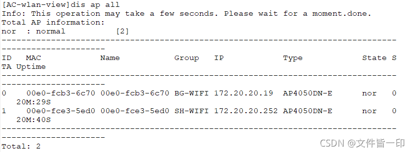
三、使用ap-id更改AP名称
[AC-wlan-view]ap-id 0---------------通过dis ap all确认AP的ID号
四、STA连接AP,测试网络
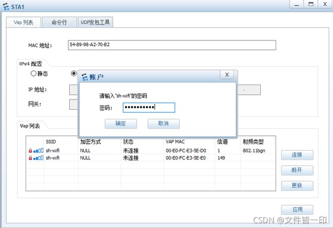
Sh-wifi采用WPA/WPA2 PSK认证方式,这里输入设置的密码Huawei@123进行连接
Bg-wifi使用Open认证方式,不需要密码验证,直接双击就可以连接
![]()
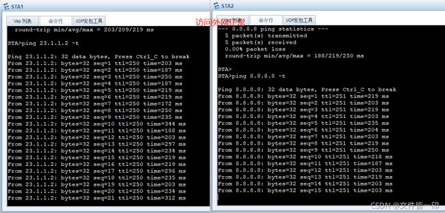
模拟SWA核心当机后,STA客户端仍然能正常访问外网。
查看SWB上VRRP信息:
STA客户端测试:
STA1和STA2都能正常访问外网。说明在SWA出现当机情况下,SWB能快速进行VRRP切换,并承载起内网的业务访问需求。
汇聚层交换机HUIJ01配置
注:在真机环境中一般需要给每个设备配置管理IP,所以汇聚层设备也要配置ospf路由,否则会无法对设备进行管理,这个实验中我没有对设备配置管理IP,故这里没有配置任何路由,直接二层透转三层转发(经核心)。
#
sysname HUIJ01
#
vlan batch 88 100 112 to 113
#
stp pathcost-standard legacy
#
stp region-configuration
region-name test
instance 1 vlan 100 112
instance 2 vlan 113
active region-configuration
#
interface GigabitEthernet0/0/1
port link-type access
port default vlan 112
stp edged-port enable
#
interface GigabitEthernet0/0/2
port link-type trunk
port trunk allow-pass vlan 2 to 4094
stp edged-port enable
#
interface GigabitEthernet0/0/3
port link-type access
port default vlan 112
stp edged-port enable
#
interface GigabitEthernet0/0/23
port link-type trunk
port trunk allow-pass vlan 88 100 112 to 113
stp instance 1 cost 20000
#
interface GigabitEthernet0/0/24
port link-type trunk
port trunk allow-pass vlan 88 100 112 to 113
stp instance 2 cost 20000
#
汇聚层交换机HUIJ02配置
注:在真机环境中一般需要给每个设备配置管理IP,所以汇聚层设备也要配置ospf路由,否则会无法对设备进行管理,这个实验中我没有对设备配置管理IP,故这里没有配置任何路由,直接二层透转三层转发(经核心)。
#
sysname HUIJ02
#
vlan batch 88 100 112 to 113
#
stp pathcost-standard legacy
#
stp region-configuration
region-name test
instance 1 vlan 100 112
instance 2 vlan 113
active region-configuration
#
interface GigabitEthernet0/0/1
port link-type access
port default vlan 113
stp edged-port enable
#
interface GigabitEthernet0/0/2
port link-type access
port default vlan 113
stp edged-port enable
#
interface GigabitEthernet0/0/3
port link-type trunk
port trunk pvid vlan 88
port trunk allow-pass vlan 88 113
port-isolate enable
#
interface GigabitEthernet0/0/23
port link-type trunk
port trunk allow-pass vlan 88 100 112 to 113
stp instance 2 cost 20000
#
interface GigabitEthernet0/0/24
interface GigabitEthernet0/0/24
port link-type trunk
port trunk allow-pass vlan 88 100 112 to 113
stp instance 1 cost 20000
#
接入层交换机配置
注:在真机环境中一般需要给每个设备配置管理IP,所以接入层设备要配置一条默认路由到核心交换机,否则会无法对设备进行管理。
另外一点,如果需要禁止用户私接小路由器,可以通过在全局视图下启用dhcp snooping enable功能,并且在业务vlan视图下启用dhcp snooping enable功能。当启用了dhcp snooping功能后,一定要在设备的上级联接口下执行dhcp snooping trust,否则客户端将无法通过dhcp获取到IP地址。
在实际环境中,如果出于对企业的网络安全管理需要,要禁止用户私自更改IP。当在设备上启用dhcp snooping功能后,我们可以通过启用IPSG功能来实现该需求,可以有效防止恶意主机盗用合法主机的IP地址仿冒合法主机非法访问网络。IPSG支持静态绑定表和动态绑定表,动态绑定表需要结合dhcp snooping功能的开启来使用,适用网络内主机比较多的环境使用。当然,开启IPSG会消耗设备的CPU和内存资源,请结合实际需求进行灵活部署。
ntp时钟同步
ntp-service server disable
ntp-service ipv6 server disable
ntp-service unicast-server 192.168.100.254
#
sysname SW1
#
vlan batch 88 100
#
interface GigabitEthernet0/0/1
port link-type access
port default vlan 100
stp edged-port enable
port-isolate enable group 1 #真机环境下,不是出于安全管理需要,不需要这个。
#
interface GigabitEthernet0/0/2
port link-type access
port default vlan 100
stp edged-port enable
port-isolate enable group 1 #真机环境下,不是出于安全管理需要,不需要这个。
#
interface GigabitEthernet0/0/3
port link-type trunk
port trunk pvid vlan 88
port trunk allow-pass vlan 88 100
port-isolate enable group1
#
interface GigabitEthernet0/0/4
port link-type trunk
port trunk allow-pass vlan 2 to 4094
#在接入层交换机绑定终端的MAC地址、接口和VLAN ,测试用
mac-address static 5489-9810-380d GigabitEthernet0/0/1 vlan 100
#
一 测试外网和内网用户访问HTTP服务器
1.外网web用户访问
查看nat会话日志
NAT Session Table Information:
Protocol : TCP(6)
SrcAddr Port Vpn : 23.1.1.2 264
DestAddr Port Vpn : 202.100.99.55 20480
NAT-Info
New SrcAddr : ----
New SrcPort : ----
New DestAddr : 172.21.100.80
New DestPort : 20480
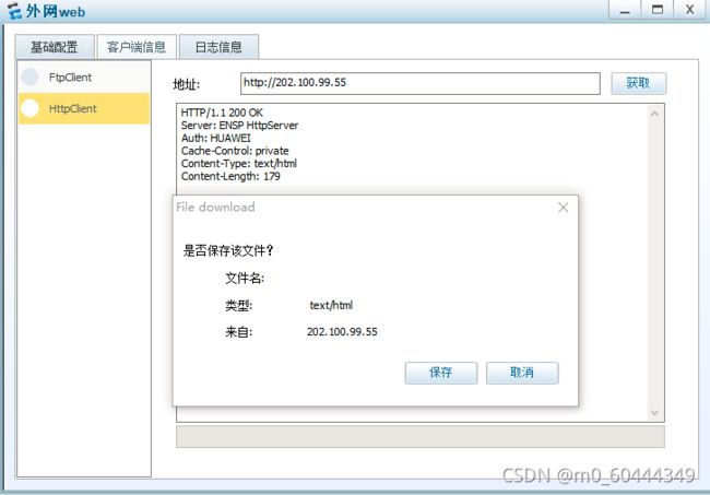
Total : 1
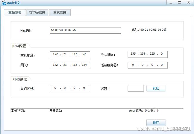
2.测试内网web112用户访问HTTP服务器
查看nat会话记录
NAT Session Table Information:
Protocol : TCP(6)
SrcAddr Port Vpn : 172.21.112.22 264
DestAddr Port Vpn : 202.100.99.55 20480
NAT-Info
New SrcAddr : 10.1.1.2
New SrcPort : 10240
New DestAddr : 172.21.100.80
New DestPort : 20480
Protocol : TCP(6)
SrcAddr Port Vpn : 23.1.1.2 520
DestAddr Port Vpn : 202.100.99.55 20480
NAT-Info
New SrcAddr : ----
New SrcPort : ----
New DestAddr : 172.21.100.80
New DestPort : 20480
Total : 2
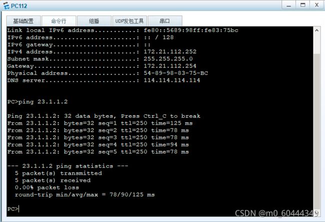
3.测试PC113用户能否上网
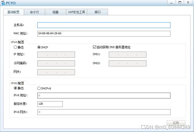
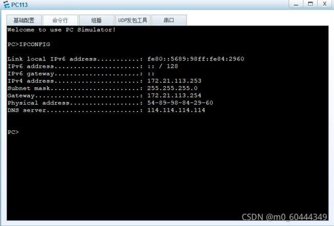
查看能否通过dhcp获取到IP地址
测试PC113用户能不能访问外网web用户(IP地址:23.1.1.2)
测试PC112用户能否访问
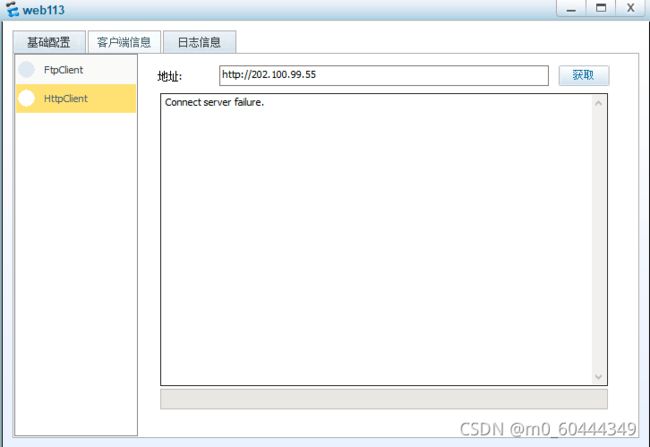
3.测试web113用户能否访问内部HTTP服务器。在路由器上只允许内网的100和112网段可以访问。现在来验证一下结果。
通过查看nat会话得知,并没有做内网的域内NAT转换
NAT Session Table Information:
Protocol : TCP(6)
SrcAddr Port Vpn : 172.21.113.22 520
DestAddr Port Vpn : 202.100.99.55 20480
NAT-Info
New SrcAddr : ----
New SrcPort : ----
New DestAddr : 172.21.100.80
New DestPort : 20480
Total : 1
二 防火墙主备故障测试
检测到主墙FW-1的上行链路出现的时候,所有流量是否都切换到备墙上,从而保障网络和业务的正常运行。
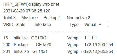
查看FW-1 VRRP切换
查看FW-2 VRRP切换
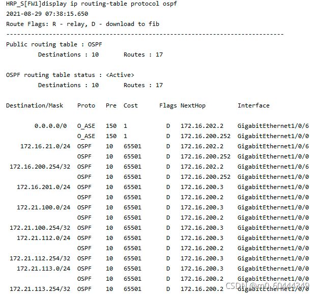
查看FW-1 OSPF路由 注:由于上联口故障或链路故障,导致FW-1发生主备切换。由于配置了hrp adjust ospf-cost,当HRP监测到主vrrrp设备出现故障时,将把所有ospf cost值加上65500。
查看FW-2 OSPF
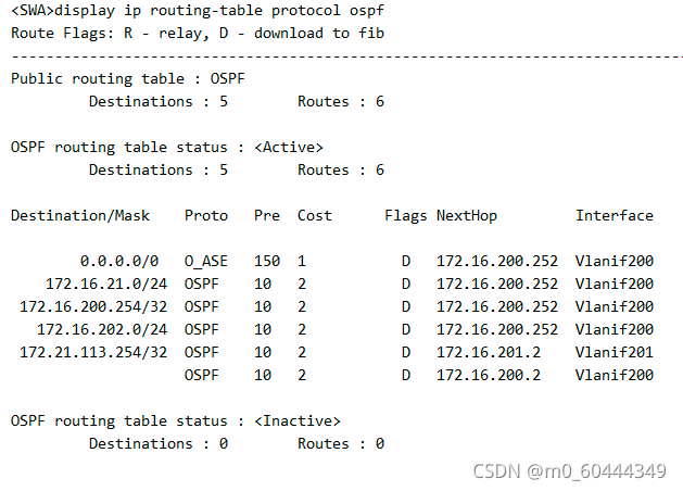
查看SWA OSPF
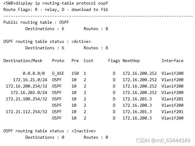
查看SWB OSPF
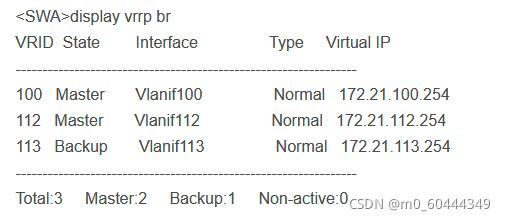
查看SWA VRRP 注:由于SWA的上联口并没有出现故障,所以这里不会发生VRRP主备切换。但由于FW-1的上行口down掉或链路故障,导致FW-1发生了主备切换。所以所有本往GE 0/0/1口走的流量都通过Eth-Trunk1 到达SWB ,然后从备墙FW-2出去。
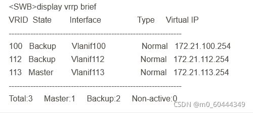
查看SWB VRRP
抓包查看数据流量走向
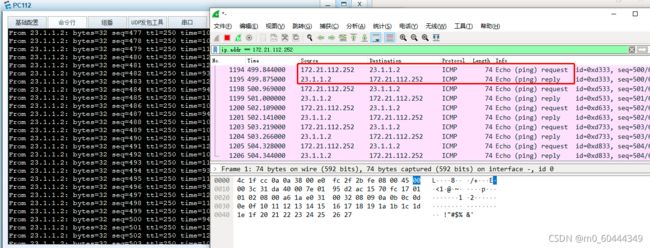
现在再试一下内网web112和外网web用户还能不能访问HTTP服务器
问题:防火墙频繁自动切换MASTER和SLAVE角色
Nov 13 2021 06:04:31 FW2 HRPI/1/CORE_STATE:1.3.6.1.4.1.2011.6.122.51.2.2.1 The H
RP core state changed due to "Unknown". (old_state=normal,new_state=abnormal(act
ive), local_priority=44998, peer_priority=44996)
Nov 13 2021 06:04:31 FW2 %%01HRPI/4/CORE_STATE(l)[46]:The HRP core state changed
due to "Unknown". (old_state=normal, new_state=abnormal(active), local_priority
=44998, peer_priority=44996)
分析:主备频繁切换与FW1上配置的track关联的ip-link项有关。因设备与对端的IP出现短暂连接中断,从而引发主备路由自动切换,然后又迅速恢复原因导致。
