实验三-RIPv2基本配置实验
目录
一、拓扑
二、地址分配表
三、目标
第 1 部分:建立网络并配置设备的基本设置
第 2 部分:配置 RIPv2 路由并进行验证
四、配置过程
第一部分:建立网络并配置设备的基本设置
步骤一:建立如拓扑图所示网络
步骤二:初始化并重新加载路由器和交换机(略)
步骤三:为每个路由器和交换机配置基本设置
步骤四:配置PC及路由器 IP编制(略)
步骤五:测试连通性
第二部分:配置RIPv2路由并进行验证
步骤一:配置RIPv2路由
步骤二:检查网络的当前状态
步骤三:禁用自动汇总
步骤四:配置并重分布用于互联网接入的默认路由
步骤五:检验路由配置
步骤六:验证连接
一、拓扑

二、地址分配表
| 设备 |
接口 |
IP 地址 |
子网掩码 |
默认网关 |
| R1 |
G0/1 |
172.30.10.1 |
255.255.255.0 |
不适用 |
| S0/0/0 (DCE) |
10.1.1.1 |
255.255.255.252 |
不适用 |
|
| R2 |
G0/0 |
209.165.201.1 |
255.255.255.0 |
不适用 |
| S0/0/0 |
10.1.1.2 |
255.255.255.252 |
不适用 |
|
| S0/0/1 (DCE) |
10.2.2.2 |
255.255.255.252 |
不适用 |
|
| R3 |
G0/1 |
172.30.30.1 |
255.255.255.0 |
不适用 |
| S0/0/1 |
10.2.2.1 |
255.255.255.252 |
不适用 |
|
| S1 |
不适用 |
VLAN 1 |
不适用 |
不适用 |
| S3 |
不适用 |
VLAN 1 |
不适用 |
不适用 |
| PC-A |
NIC |
172.30.10.3 |
255.255.255.0 |
172.30.10.1 |
| PC-B |
NIC |
209.165.201.2 |
255.255.255.0 |
209.165.201.1 |
| PC-C |
NIC |
172.30.30.3 |
255.255.255.0 |
172.30.30.1 |
三、目标
第 1 部分:建立网络并配置设备的基本设置
第 2 部分:配置 RIPv2 路由并进行验证
- 在路由器上配置 RIPv2 并验证其是否运行。
- 配置被动接口。
- 检查路由表。
- 禁用自动汇总。
- 配置默认路由。
- 检验端到端连通性
四、配置过程
第一部分:建立网络并配置设备的基本设置
步骤一:建立如拓扑图所示网络
在配置拓扑图时,由于路由器上默认没有相应的Serial接口,需要通过加板槽的方式添加,操作如下:
① 将设备关机

② 添加相应的模块

③ 添加完成后开机
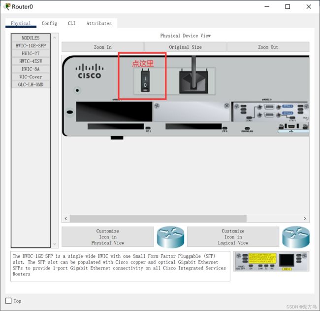
两台路由器都添加后就可以连接Serial接口了,根据本题的要求,需要用DCE线(标记的这根),此外,拓扑上的小时钟在哪个位置,就先接哪个接口。

步骤二:初始化并重新加载路由器和交换机(略)
步骤三:为每个路由器和交换机配置基本设置
注:个人建议为了配置快速这一部分放在最后做,因为每次登录都输密码实在太麻烦了。
① 禁用DNS查找
以R1为例:
R1(config)#no ip domain-lookup ② 配置设备名称
以R1为例:
Cisco(config)#hostname R1③ 配置口令加密
以S3为例:
S3(config)#enable secret pass④ 指定class为特权EXEC密码
以R2为例:
R2(config)#enable password class⑤ 指定cisco为控制台和vty密码
以R3为例:
R3(config)#line console 0
R3(config-line)#password cisco
R3(config-line)#exi
R3(config)#line vty 0 4
R3(config-line)#password cisco
⑥ 配置MOTD标语,以警告用户禁止未经授权的访问
以R2为例:
R2(config)#banner motd c
Enter TEXT message.  End with the character 'c'.
加标语
c
⑦ 为控制台行配置 logging synchronous
以R3为例:
R3(config)#line console 0
R3(config-line)#logging synchronous
⑧ 为所有接口配置地址分配表中列出的IP地址(略)
⑨ 为每个具有IP地址的接口配置描述
以R1为例:
R1(config)#int s0/0/0
R1(config-if)#description +描述
⑩ 将时钟频率(若适用)配置为DCE串行接口
以R1为例:
R1(config)#int s0/0/0
R1(config-if)#clock rate +频率
11. 将运行配置复制到启动配置中
以R1为例:
R1#copy running-config startup-config
Destination filename [startup-config]?
步骤四:配置PC及路由器 IP编制(略)
注:IP地址配置的时候注意下别配错了,特别是PC的掩码,注意一下自动填充的掩码是否和给的地址表一致;记得顺手把所有设备的接口打开。
步骤五:测试连通性
以PC-A为例:
C:\>ping 172.30.10.1

Pinging 172.30.10.1 with 32 bytes of data:

Reply from 172.30.10.1: bytes=32 time<1ms TTL=255
Reply from 172.30.10.1: bytes=32 time<1ms TTL=255
Reply from 172.30.10.1: bytes=32 time<1ms TTL=255
Reply from 172.30.10.1: bytes=32 time=4ms TTL=255

Ping statistics for 172.30.10.1:
    Packets: Sent = 4, Received = 4, Lost = 0 (0% loss),
Approximate round trip times in milli-seconds:
    Minimum = 0ms, Maximum = 4ms, Average = 1ms
以 R1为例:
R1#ping 10.1.1.2

Type escape sequence to abort.
Sending 5, 100-byte ICMP Echos to 10.1.1.2, timeout is 2 seconds:
!!!!!
Success rate is 100 percent (5/5), round-trip min/avg/max = 4/6/8 ms
此时,PC之间无法相互通信,每台PC都能与直连路由器(网关)通信,路由器之间能够相互通信。
第二部分:配置RIPv2路由并进行验证
步骤一:配置RIPv2路由
① 在R1上配置RIPv2 作为路由协议,并通告适当的相连网络。
R1# conf ter
R1(config)# router rip
R1(config-router)# version 2
R1(config-router)# passive-interface g0/1
R1(config-router)# network 172.30.0.0
R1(config-router)# network 10.0.0.0
② 在R3上配置RIPv2 并使用网络语句添加适当的相连网络并阻止 LAN 接口上的路由更新。
R3# conf ter
R3(config)# router rip
R3(config-router)# version 2
R3(config-router)# passive-interface g0/1
R3(config-router)# network 172.30.0.0
R3(config-router)# network 10.0.0.0
③ 在 R2 上配置 RIPv2 并使用网络语句添加适当的相连网络。请勿通告 209.165.201.0 网络。
R2# conf ter
R2(config)# router rip
R2(config-router)# version 2
R2(config-router)# network 10.0.0.0注:由于不再通告与 G0/0 接口关联的网络,因此不必在 R2 上将此接口设为被动。
步骤二:检查网络的当前状态
该部分涉及到的命令行如下:
show ip interface brief //查看接口所在链路状态
ping //检验连通性
debug ip rip //抓取有关RIP协议的数据包
undebug all //关闭抓包
show ip protocols //查看路由协议
show run //查看运行中的配置
show ip route //查看路由表
步骤三:禁用自动汇总
对R1:
R1(config)# router rip
R1(config-router)# no auto-summary
R1(config-router)# end
R1# clear ip route *
对R2:
R2(config)# router rip
R2(config-router)# no auto-summary
R2(config-router)# end
R2# clear ip route *
对R3:
R3(config)# router rip
R3(config-router)# no auto-summary
R3(config-router)# end
R3# clear ip route *
注:三台设备一定都要禁用自动汇总,不然会导致部分路由缺失,网络互通失败。
步骤四:配置并重分布用于互联网接入的默认路由
① 配置R2的缺省静态路由到PC-B
R2(config)# ip route 0.0.0.0 0.0.0.0 209.165.201.2② 在RIP中导入缺省路由
R2(config)# router rip
R2(config-router)# default-information originate
步骤五:检验路由配置
R1#show ip route步骤六:验证连接
以PC-A为例:
C:\>ping 209.165.201.2

Pinging 209.165.201.2 with 32 bytes of data:

Request timed out.
Reply from 209.165.201.2: bytes=32 time=10ms TTL=126
Reply from 209.165.201.2: bytes=32 time=8ms TTL=126
Reply from 209.165.201.2: bytes=32 time=6ms TTL=126

Ping statistics for 209.165.201.2:
    Packets: Sent = 4, Received = 3, Lost = 1 (25% loss),
Approximate round trip times in milli-seconds:
    Minimum = 6ms, Maximum = 10ms, Average = 8ms