【radon变换原理讲解及利用python库函数快速实现】
radon变换原理讲解及利用python库函数快速实现
- 前言
-
- 成像流程
- 坐标转换原理
- radon变换过程
- 代码实现
-
- radon变换结果
- radon逆变换
前言
最近遇到一个CT成像仿真的问题,以前只知道大概原理,具体成像算法也没有接触过,在此记录一下基本理论和代码实现。
本文主要参考了以下文章:
https://zhuanlan.zhihu.com/p/79722768
https://scikit-image.org/docs/stable/auto_examples/transform/plot_radon_transform.html
成像流程
简化来说射线穿过2-D的物体会产生一个1-D的数据,这个1-D的数据就是射线经过物体的衰减程度,通过衰减程度就能就算出2-D物体内部的结构组成。
这个1-D上的每个数据就是一条线上的积分结果,需要对线进行求解就能得到具体的图像。
所以成像的流程就是将接收板上的数据进行逆变换后的结果。
坐标转换原理
射线穿过物体的衰减函数为 f ( x , y ) f(x,y) f(x,y),得到射线穿过物体在该方向的衰弱度(intensity),(想象一条线在穿过一个二维图像上每个点都存在衰减的情况,所以其积分结果就是穿过后的intensity, f ( x , y ) f(x,y) f(x,y)就是当前穿过这条线中的内容,求得线越多组成的图像就越清晰)。
R L = ∫ L f ( x , y ) d s R L : I n t e n s i t y a t L R_L = \int_L f(x,y)ds \enspace R_L:Intensity \enspace at \enspace L RL=∫Lf(x,y)dsRL:IntensityatL
目标:求解 f ( x , y ) f(x,y) f(x,y),就需要去掉积分==========》工具:傅里叶变换
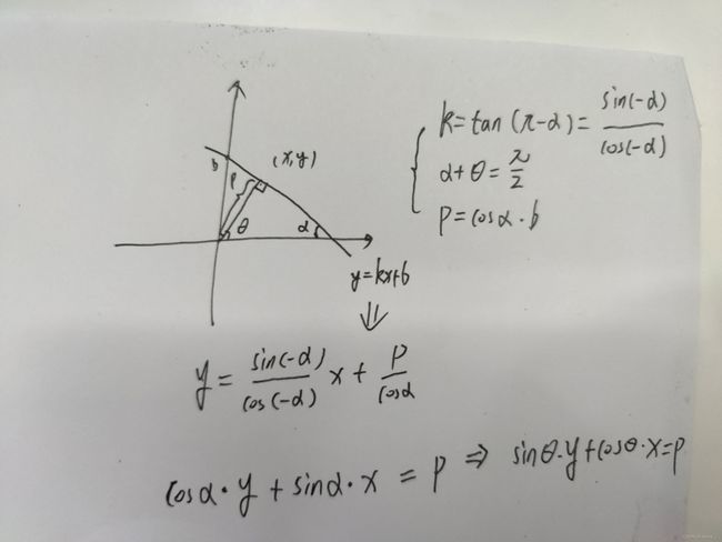
L表达方式: 常规直线 y = k x + b y = kx+b y=kx+b,这种形式不利于求解,转换为角度表示形式。
L L L参数说明
P:点 ( x , y ) (x,y) (x,y)到原点的距离。
θ \theta θ: L L L的法线方向。
x cos θ + y sin θ = p x\cos\theta +y\sin\theta = p xcosθ+ysinθ=p
radon变换过程
此处不再细讲,可以看参考文章1,里面讲的很细了。
R L = ∫ L f ( x , y ) d s R_L = \int_L f(x,y)ds RL=∫Lf(x,y)ds
R ( θ , p ) = ∫ ( θ , p ) f ( x , y ) d s R(\theta,p) = \int_{(\theta,p)}f(x,y)ds R(θ,p)=∫(θ,p)f(x,y)ds
成像的过程就是反变换的过程。
代码实现
radon变换结果
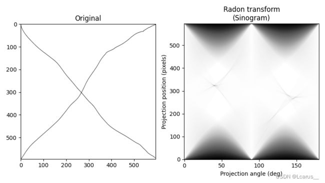
首先演示radon变换的结果,注意这个结果就是接收板上能够得到的结果。
from cgitb import grey
import numpy as np
import matplotlib.pyplot as plt

from skimage import transform
from skimage.transform import radon
from skimage import io

image = io.imread('IMG/example.jpg',as_gray = grey)

image = transform.resize(image,(image.shape[0],image.shape[0])) ##将图像转换为正方形,方便后续滤波计算

# 图像坐标转换为(theta,p)
fig, (ax1, ax2) = plt.subplots(1, 2, figsize=(8, 4.5))
ax1.set_title("Original")
ax1.imshow(image, cmap=plt.cm.Greys_r)
theta = np.linspace(0., 180., max(image.shape), endpoint=False)
sinogram = radon(image, theta=theta)
print(np.shape(sinogram))
dx, dy = 0.5 * 180.0 / max(image.shape), 0.5 / sinogram.shape[0]
ax2.set_title("Radon transform\n(Sinogram)")
ax2.set_xlabel("Projection angle (deg)")
ax2.set_ylabel("Projection position (pixels)")
ax2.imshow(sinogram, cmap=plt.cm.Greys_r,
           extent=(-dx, 180.0 + dx, -dy, sinogram.shape[0] + dy),
           aspect='auto')
fig.tight_layout()
plt.show()
左边是我手绘的结果,右边是经过Radon变换的结果。此结果存疑,和图像读入格式相关。

radon逆变换
#反变化结果
from skimage.transform import iradon
size = np.shape(image)
reconstruction_fbp = iradon(sinogram,theta=theta, filter_name='cosine')
error = reconstruction_fbp - image
print(f'FBP rms reconstruction error: {np.sqrt(np.mean(error**2)):.3g}')

imkwargs = dict(vmin=-0.2, vmax=0.2)
fig, (ax1, ax2) = plt.subplots(1, 2, figsize=(8, 4.5),
                               sharex=True, sharey=True)
ax1.set_title("Reconstruction\nFiltered back projection")
ax1.imshow(reconstruction_fbp, cmap=plt.cm.Greys_r)
ax2.set_title("Reconstruction error\nFiltered back projection")
ax2.imshow(reconstruction_fbp - image, cmap=plt.cm.Greys_r, **imkwargs)
plt.show()
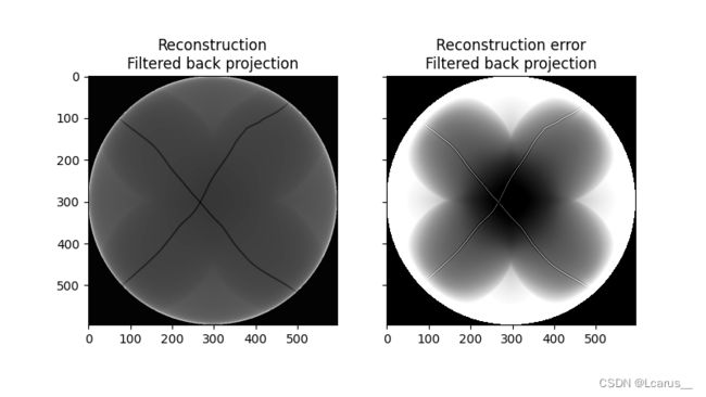
右图是将上一节中得到结果进行逆变换后的成像结果,其成像结果也与滤波器的设置有关,这个后续补充。

通过以上全部流程,就对CT成像的原理及过程有了一个大概的认识。
