OpenFOAM的圆柱绕流算例记录
圆柱绕流是流体力学里最经典的算例之一,受到众多学者的“喜爱”。初学CFD的人除了空腔、管道流之外,最先接触的莫过于圆柱绕流了。圆柱绕流能反映流体流过障碍物时的各种情况:层流向湍流的转捩、流体的剪切与分离、边界层、卡门涡街现象等等,是深入理解流动机理的重要算例。因为经常要算圆柱绕流,在这里做一些记录,记录一些细节,以防以后忘掉。这次做Re=200时的圆柱绕流算例,画网格用ICEM,CFD软件用开源软件OpenFOAM,后处理用tecplot。算例文件可以看着我下面的内容进行设置,也可以在我的主页找找上传的文件包。
1. 前处理:画网格
用ICEM画网格。圆柱直径D=1m,计算域为圆形直径为30D。因为是层流的网格,第一层网格高度没有严格限制,网格数为160x160。我在b站上传了画网格的视频过程,可以搜chansFoam关注一下。具体过程不在这里详说。

2. OpenFOAM计算
2.1 载入网格及修改边界类型
在OpenFOAM里随便找一个模板算例。首先把刚刚画好的网格msh文件复制到case文件夹中:

在终端输入:
fluentMeshToFoam cylinder2d.msh -2D 1这样就可以把fluent的网格格式转成OpenFOAM能用的。后面-2D的指令是设置z方向厚度的,因为是2维的网格,但是在OpenFOAM里只有三位的算例,所以得z方向拉伸一层。这一层高度我设为1。接下来打开constant/polyMesh/boundary,修改一下边界条件类型,将:

改成:

这么做的原因是,在ICEM中画完网格设置边界条件时,先把所有的边界设置为wall会比较方便,只需要在OpenFOAM里统一修改即可。
2.2 设置初值和边界条件
打开0文件夹,把U和p文件设置成如下所示:
U:
/*--------------------------------*- C++ -*----------------------------------*\
| =========                 |                                                 |
| \\      /  F ield         | OpenFOAM: The Open Source CFD Toolbox           |
|  \\    /   O peration     | Version:  4.x                                   |
|   \\  /    A nd           | Web:      www.OpenFOAM.org                      |
|    \\/     M anipulation  |                                                 |
\*---------------------------------------------------------------------------*/
FoamFile
{
    version     2.0;
    format      ascii;
    class       volVectorField;
    object      U;
}
// * * * * * * * * * * * * * * * * * * * * * * * * * * * * * * * * * * * * * //

dimensions      [0 1 -1 0 0 0 0];

internalField   uniform (17 0 0);

boundaryField
{
    IN
    {

        type            fixedValue;
        value           uniform (17 0 0);
    }

    OUT
    {
        type            zeroGradient;
    }

    CYLINDER
    {
        type            fixedValue;
        value           uniform (0 0 0);
    }


    frontAndBackPlanes
    {
        type            empty;
    }

}

// ************************************************************************* //
p:
/*--------------------------------*- C++ -*----------------------------------*\
| =========                 |                                                 |
| \\      /  F ield         | OpenFOAM: The Open Source CFD Toolbox           |
|  \\    /   O peration     | Version:  4.x                                   |
|   \\  /    A nd           | Web:      www.OpenFOAM.org                      |
|    \\/     M anipulation  |                                                 |
\*---------------------------------------------------------------------------*/
FoamFile
{
    version     2.0;
    format      ascii;
    class       volScalarField;
    object      p;
}
// * * * * * * * * * * * * * * * * * * * * * * * * * * * * * * * * * * * * * //

dimensions      [0 2 -2 0 0 0 0];

internalField   uniform 0;

boundaryField
{
    IN
    {
        type            zeroGradient;
    }

    OUT
    {
        type            fixedValue;
        value			uniform 0;
    }

    CYLINDER
    {
        type            zeroGradient;
    }

    frontAndBackPlanes
    {
        type            empty;
    }

}

// ************************************************************************* //
这都是十分标准的边界条件了。初值的话,压强设置为0,速度为17m/s(Ma=0.05)。
2.3 运动粘度
打开constant/transportProperties,修改nu的数值。Re为200时,nu=17*1/200=0.085。
![]()
2.4 数值格式
打开system/fvSchemes,修改如下:
/*--------------------------------*- C++ -*----------------------------------*\
| =========                 |                                                 |
| \\      /  F ield         | OpenFOAM: The Open Source CFD Toolbox           |
|  \\    /   O peration     | Version:  4.x                                   |
|   \\  /    A nd           | Web:      www.OpenFOAM.org                      |
|    \\/     M anipulation  |                                                 |
\*---------------------------------------------------------------------------*/
FoamFile
{
    version     2.0;
    format      ascii;
    class       dictionary;
    object      fvSchemes;
}
// * * * * * * * * * * * * * * * * * * * * * * * * * * * * * * * * * * * * * //
ddtSchemes
{
   default         backward;
}

gradSchemes
{
    default 	     Gauss linear;
}

divSchemes
{
    default         none;
    div(phi,U)      Gauss linearUpwind grad(U);
}

laplacianSchemes
{
    default         Gauss linear limited 1;
}

interpolationSchemes
{
    default         linear corrected;
}

snGradSchemes
{
   default           corrected;
}

// ************************************************************************* //
值得一提的是对流项格式。这里用的是二阶迎风格式。如果用一阶迎风(Gauss upwind),则不会出现卡门涡街,而是收敛到下面的情况,左为x方向速度云图,右为压强云图。阻力系数会趋于稳定,升力系数以10e-6的幅值在0上下浮动(相当于不变)。


2.5 解方程的的设置
在icoFoam算法(SIMPLE)的框架下,设置完数值格式之后,程序就会构造一个非常巨大的稀疏矩阵。接下来的工作就是把这个线性方程组解开:

其中,x代表流场变量,A为系数矩阵,是一个十分稀疏的矩阵,b代表源场、显式项等。OpenFOAM内置了许多解方程的工具,都在system/fvSolution里进行设置:
/*--------------------------------*- C++ -*----------------------------------*\
| =========                 |                                                 |
| \\      /  F ield         | OpenFOAM: The Open Source CFD Toolbox           |
|  \\    /   O peration     | Version:  4.x                                   |
|   \\  /    A nd           | Web:      www.OpenFOAM.org                      |
|    \\/     M anipulation  |                                                 |
\*---------------------------------------------------------------------------*/
FoamFile
{
    version     2.0;
    format      ascii;
    class       dictionary;
    object      fvSolution;
}
// * * * * * * * * * * * * * * * * * * * * * * * * * * * * * * * * * * * * * //

solvers
{

    p
    {
        solver          PCG;
        preconditioner  DIC;
        tolerance       1e-07;
        relTol          0;

    }

    pFinal
    {
        $p;
        relTol          0;
    }

    U
    {
        solver          PBiCG;
        preconditioner  DILU;
        tolerance       1e-08;
        relTol          0;
    }

}

PISO
{
    nCorrectors     2;
    nNonOrthogonalCorrectors 2;
    pRefCell        0;
    pRefValue       0;
}

// ************************************************************************* //
习惯上,压强矩阵我用PCG比较多,另外也可以选GAMG。速度矩阵用PBiCG。这些是什么,涉及到算法的问题,可以看一些书,这里不详细说。注意到后面的nCorrectors和nNonOrthogonalCorrectors,分别代表PISO算法校正的次数和非正交修正的次数。刚刚画的圆柱绕流网格严格来说是非正交的,这里设置了两次。
2.6 计算设置
打开system/controlDict进行计算上的一些设置,包括时间步长、开始和结束的时间、多少步输出一次以及输出一些后处理要用的信息。
/*--------------------------------*- C++ -*----------------------------------*\
| =========                 |                                                 |
| \\      /  F ield         | OpenFOAM: The Open Source CFD Toolbox           |
|  \\    /   O peration     | Version:  4.x                                   |
|   \\  /    A nd           | Web:      www.OpenFOAM.org                      |
|    \\/     M anipulation  |                                                 |
\*---------------------------------------------------------------------------*/
FoamFile
{
    version     2.0;
    format      ascii;
    class       dictionary;
    object      controlDict;
}
// * * * * * * * * * * * * * * * * * * * * * * * * * * * * * * * * * * * * * //

application     icoFoam;

//startFrom       startTime;
startFrom       latestTime;

startTime       0;

stopAt          endTime;
//stopAt	  writeNow;

endTime         6;
//endTime         500;

//deltaT          0.005;
//deltaT          0.01;
//deltaT          0.02;
deltaT          0.0005;

writeControl    runTime;
/*
adjustableRunTime
clockTime
cpuTime
runTime
timeStep
*/

writeInterval   0.5;

/*
secondaryWriteControl    cpuTime;
secondaryWriteInterval   1000;
secondaryPurgeWrite      1;
*/

purgeWrite      20;

writeFormat     ascii;

writePrecision  8;

writeCompression off;

timeFormat      general;

timePrecision   6;

runTimeModifiable true;

// ************************************************************************* //

functions
{

    fieldAverage
    {
        type            fieldAverage;
        functionObjectLibs ("libfieldFunctionObjects.so");
        enabled         true;
        writeControl   outputTime;

	//writeControl   timeStep;
	//writeInterval  100;

	//cleanRestart true;

	//timeStart       20;
	//timeEnd         200;

        fields
        (
            p
            {
                mean        on;
                prime2Mean  on;
                base        time;
            }
            U
            {
                mean        on;
                prime2Mean  on;
                base        time;
            }

        );
    }
    forceCoeffs
    {
         type forceCoeffs;
         functionObjectLibs ("libforces.so");
         patches (CYLINDER);
         log true;
         rho rhoInf;
         rhoInf 1;
         CofR (0 0 0);
         liftDir (0 1 0);
         dragDir (1 0 0);
         pitchAxis (0 0 1);
         magUInf 17;
         lRef 1;
         Aref 1;
         writeControl    timeStep;
         writeInterval   1;
     }
};
这里特别说明计算步长和总时间。计算步长的设置最好使得计算时最大库朗数(Courant,CFL)小于1。虽然说SIMPLE是半隐式的求解方法,隐式格式无条件稳定,我们还是希望流场的计算能稳定一些。这里设置deltaT为0.0005,max CFL在0.5左右。总时长取6s,差不多是20个周期的时间。计算过程如下:
首先考虑圆柱绕流的无量纲频率St数:
![]()
一般圆柱绕流的St在0.2左右,f为实际涡脱落的频率,取倒数计算得到一个涡脱落周期的时间:
![]()
因此20个周期取6s。做圆柱绕流算例要关注平均场、扰动场和升阻力系数,这些在controlDict后面的functions中进行设置,在此不一一细说。
2.7 开始计算
如果要并行,就要设置decomposeParDict,然后用mpi指令进行计算。这里只用单核进行,在终端直接输入:
icoFoam即可开始计算。计算时间视计算性能来决定。
3. 后处理看结果
算完之后,用tecplot打开postProcessing/forceCoeffs/0,看一下升阻力系数曲线:


可以看到后半段是进入了相对稳定的阶段,流场出现了卡门涡街,升阻力系数呈周期性变化。从升力系数估算到St=0.235,平均阻力系数为1.35。对比一些文献:

这里看出和文献还是有一些出入的,具体原因有网格分辨率、数值格式、计算方法等等,这里面单一个拎出来都是很大的课题,慢慢去掌握吧。后面自己再慢慢修改,这里就不放出来了。后面放一些流场的图:
流向平均速度云图:

平均压强云图:

还有涡量图,涡量的计算可以看我以前发的视频。
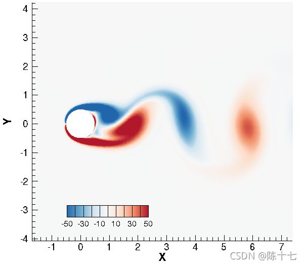
当然还需要提取某一条线上的流场变量和文献的作对比,现在这篇内容太多了,我放到后面再详细记录。
总结
这次在OpenFOAM上对雷诺数为200的圆柱绕流算例进行了比较完整的模拟仿真,包括画网格、设置算例、计算以及后处理比较结果。CFD计算流体力学是一门涉及面很广同时又需要你每一项都精通的学科,因为如果某一个环节处理不当,是会影响整一个仿真的效果的,包括但不限于网格分辨率、数值格式的选取、计算方法的选择、解方程的设置等等,每一项都需要仔细地进行。好在CFD是活用计算机的一种工具,以程序的形式进行流体力学的模拟,具有知识的复用性,也就可以在设备里储存起来,也方便大家的交流和分享。