基于ARDUINO CLOUD的IMU采样及Processing可视化
本文主要介绍了Arduino cloud的用法和nano rp2040IMU调用方法,以及奈何col的IMU数据可视化的移植方法。
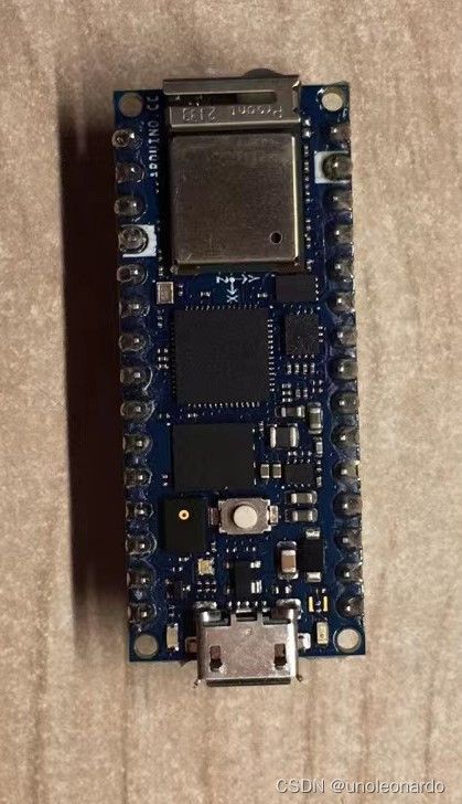
之前听说树莓派和ARDUINO合作出了一款开发板:还带WiFi/BT模块的,IMU,麦克风。看上去这一套还挺多的,就决定试试。
但试了以后才发现它能干的MPU6050也能干.......麦克风也是个摆设,也就能看个热闹,看看曲线,分析的话根本不太可能。最后就只剩下那个ARDUINO官方支持的esp32模组了。经过我的努力,在官网上发现了一个组件:
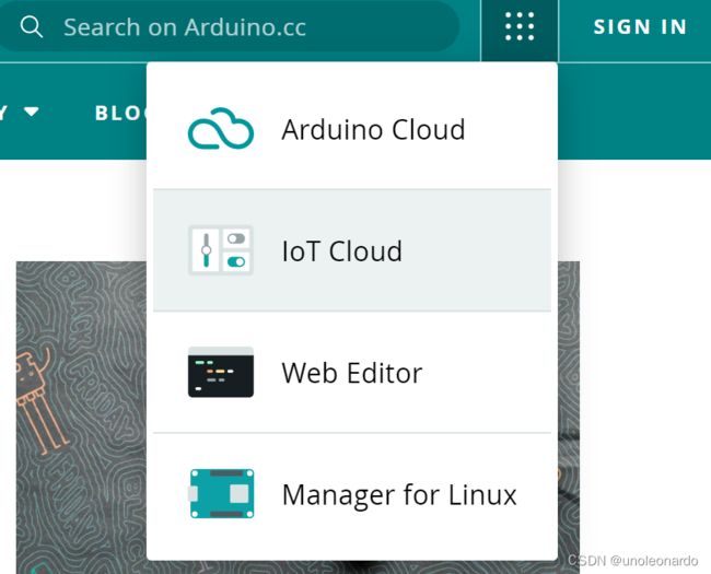
 IOT CLOUD 物联网组件
看上去这是个好东西,但国内用的人好像不多,资料也不多。我找了半天只发现了几篇博文,还用的都是esp8266。我一开始还以为只要在IOT平台里把组件弄好,再在离线版里配置网络就好了......最后还是跑了官方的例程才弄明白的。
/*
  Sketch generated by the Arduino IoT Cloud Thing "Cloud Blink"

  Arduino IoT Cloud Variables description

  The following variables are automatically generated and updated when changes are made to the Thing

  bool led;

  Variables which are marked as READ/WRITE in the Cloud Thing will also have functions
  which are called when their values are changed from the Dashboard.
  These functions are generated with the Thing and added at the end of this sketch.
*/
#include "thingProperties.h"

void setup() {
  // Initialize serial and wait for port to open:
  Serial.begin(9600);
  // This delay gives the chance to wait for a Serial Monitor without blocking if none is found
  delay(1500);

  // Defined in thingProperties.h
  initProperties();

  // Connect to Arduino IoT Cloud
  ArduinoCloud.begin(ArduinoIoTPreferredConnection);

  /*
     The following function allows you to obtain more information
     related to the state of network and IoT Cloud connection and errors
     the higher number the more granular information you’ll get.
     The default is 0 (only errors).
     Maximum is 4
 */
  setDebugMessageLevel(2);
  ArduinoCloud.printDebugInfo();
  pinMode(LED_BUILTIN, OUTPUT);
  pinMode(13,OUTPUT);
  digitalWrite(13,HIGH);
  delay(200);
  digitalWrite(13,LOW);
  delay(200);
}

void loop() {
  ArduinoCloud.update();
  digitalWrite(LED_BUILTIN, led);
  digitalWrite(13,led);
}

/*
  Since Led is READ_WRITE variable, onLedChange() is
  executed every time a new value is received from IoT Cloud.
*/
void onLedChange()  {
  Serial.print("Led status changed:");
  Serial.println(led);
}
官方例程:注意要在web版里打开,离线版里是没有云的库的 。
在这里还是要吐槽一下ARDUINO官方的:cloud blink 真的是十分cloud,发过去开灯信号,它不在现实中点灯,它给你在云上点......搞得我一度怀疑板子是不是烧了。还是我把13脚的电平控制给加上去的。
ARDUINO CLOUD 用法:
之后想将IMU的数据穿到云上,于是跑了库自带的例程:但跑了一半板子烧了,于是换了一块Nano 33 IoT 。两块板子的例程都附上:
#include
unsigned long microsPerReading,microsP;
unsigned long microsNow;

void setup() {
  Serial.begin(38400);
  while (!Serial) {
    // wait for serial port to connect. Needed for native USB port only
  }
  if (!IMU.begin()) {
    while (true); // halt program
  }
  microsPerReading = 1000000 / 25;
  microsP = micros();
}

void loop() {
  float aX, aY, aZ;
  float gX, gY, gZ;
  float gXs,gYs,gZs;
  microsNow = micros();
  if (microsNow - microsP >= microsPerReading) {
  if (
    IMU.accelerationAvailable()
    && IMU.gyroscopeAvailable()
  ) {
    IMU.readAcceleration(aX, aY, aZ);
    IMU.readGyroscope(gX, gY, gZ);

    Serial.print(aX);
    Serial.print(aY);
    Serial.print(aZ);
    Serial.print(gX);
    Serial.print(gY);
    Serial.println(gZ);

    microsP = microsP + microsPerReading;
   }
  }
  }
Nano 33 IoT 例程
#include

float Ax, Ay, Az;
float Gx, Gy, Gz;

void setup() {
  Serial.begin(9600);

  while(!Serial);

  if (!IMU.begin()) {
    Serial.println("Failed to initialize IMU!");
    while (1);
  }

  Serial.print("Accelerometer sample rate = ");
  Serial.print(IMU.accelerationSampleRate());
  Serial.println("Hz");
  Serial.println();

  Serial.print("Gyroscope sample rate = ");
  Serial.print(IMU.gyroscopeSampleRate());
  Serial.println("Hz");
  Serial.println();

}

void loop() {

  if (IMU.accelerationAvailable()) {
    IMU.readAcceleration(Ax, Ay, Az);

    Serial.println("Accelerometer data: ");
    Serial.print(Ax);
    Serial.print('\t');
    Serial.print(Ay);
    Serial.print('\t');
    Serial.println(Az);
    Serial.println();
  }

  if (IMU.gyroscopeAvailable()) {
    IMU.readGyroscope(Gx, Gy, Gz);

    Serial.println("Gyroscope data: ");
    Serial.print(Gx);
    Serial.print('\t');
    Serial.print(Gy);
    Serial.print('\t');
    Serial.println(Gz);
    Serial.println();
  }

delay(500);

}
Nano rp2040 conncet 例程
官网资料:
IMU.begin();//initializes the library.
IMU.accelerationSampleRate();// reads the sampling rate in Hz.
IMU.accelerationAvailable();//checks if there's data available from the IMU.
IMU.readAcceleration(Ax, Ay, Az);//reads the accelerometer, and returns the value .
IMU (Inertial Measurement Unit)
The LSM6DSOXTR sensor.An IMU is a component that exists of different sensors that records data such as specific force, angular rate, orientation. On the Nano RP2040 Connect, there is one gyroscope and one accelerometer. Let's take a look at how they work!
Accelerometer
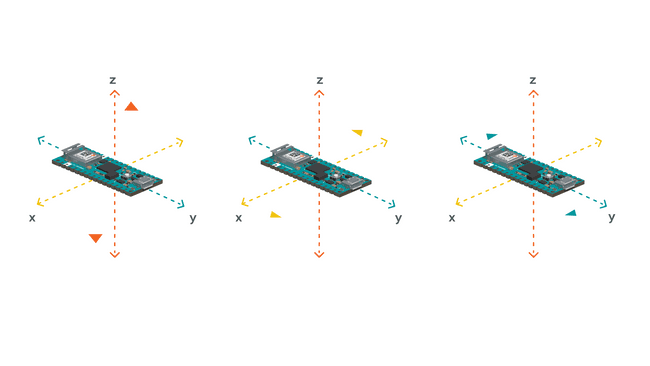
An accelerometer is an electromechanical device used to measure acceleration forces. Such forces may be static, like the continuous force of gravity or, as is the case with many mobile devices, dynamic to sense movement or vibrations.
Illustration of acceleration.In this example, we will use the accelerometer as a "level" that will provide information about the position of the board. With this application we will be able to read what the relative position of the board is, as well as the degrees by tilting the board up, down, left or right.
Gyroscope
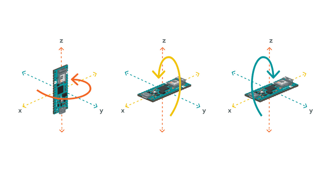
A gyroscope sensor is a device that can measure and maintain the orientation and angular velocity of an object. Gyroscopes are more advanced than accelerometers, as they can measure the tilt and lateral orientation of an object, whereas an accelerometer can only measure its linear motion.
Illustration of gyroscope.Gyroscope sensors are also called "Angular Rate Sensors" or "Angular Velocity Sensors". Measured in degrees per second, angular velocity is the change in the rotational angle of the object per unit of time.
In this example, we will use the gyroscope as an indicator for the direction of the force that is applied to the board. This will be achieved by swiftly moving the board for an instant in four directions: forward, backward, to the left and to the right. The results will be visible through the Serial Monitor.
引用自:Accessing IMU Data on Nano RP2040 Connect | Arduino Documentation | Arduino Documentation
但是云端数据传输太慢了,没能传输IMU数据到云上。
之后无意之中发现了奈何col的IMUprocessing可视化,于是我也移植到了Nano 33 IoT上:
*在此感谢奈何col的文章:【Arduino101教程】processing姿态数据可视化-Arduino爱好者 - Powered by Discuz!
processing端:
import processing.serial.*;
Serial myPort;

float yaw = 0.0;
float pitch = 0.0;
float roll = 0.0;

void setup()
{
  size(600, 500, P3D);

  // if you have only ONE serial port active
  //myPort = new Serial(this, Serial.list()[0], 9600); // if you have only ONE serial port active

  // if you know the serial port name
  myPort = new Serial(this, "COM14", 38400);                    // Windows
  //myPort = new Serial(this, "/dev/ttyACM0", 9600);             // Linux
  //myPort = new Serial(this, "/dev/cu.usbmodem1217321", 9600);  // Mac

  textSize(16); // set text size
  textMode(SHAPE); // set text mode to shape
}

void draw()
{
  serialEvent();  // read and parse incoming serial message
  background(255); // set background to white
  lights();

  translate(width/2, height/2); // set position to centre

  pushMatrix(); // begin object

  float c1 = cos(radians(roll));
  float s1 = sin(radians(roll));
  float c2 = cos(radians(pitch));
  float s2 = sin(radians(pitch));
  float c3 = cos(radians(yaw));
  float s3 = sin(radians(yaw));
  applyMatrix( c2*c3, s1*s3+c1*c3*s2, c3*s1*s2-c1*s3, 0,
               -s2, c1*c2, c2*s1, 0,
               c2*s3, c1*s2*s3-c3*s1, c1*c3+s1*s2*s3, 0,
               0, 0, 0, 1);

  drawArduino();

  popMatrix(); // end of object

  // Print values to console
  print(roll);
  print("\t");
  print(pitch);
  print("\t");
  print(yaw);
  println();
}

void serialEvent()
{
  int newLine = 13; // new line character in ASCII
  String message;
  do {
    message = myPort.readStringUntil(newLine); // read from port until new line
    if (message != null) {
      String[] list = split(trim(message), " ");
      if (list.length >= 4 && list[0].equals("Orientation:")) {
        yaw = float(list[1]); // convert to float yaw
        pitch = float(list[2]); // convert to float pitch
        roll = float(list[3]); // convert to float roll
      }
    }
  } while (message != null);
}

void drawArduino()
{
  /* function contains shape(s) that are rotated with the IMU */
  stroke(0, 90, 90); // set outline colour to darker teal
  fill(0, 130, 130); // set fill colour to lighter teal
  box(300, 10, 200); // draw Arduino board base shape

  stroke(0); // set outline colour to black
  fill(80); // set fill colour to dark grey

  translate(60, -10, 90); // set position to edge of Arduino box
  box(170, 20, 10); // draw pin header as box

  translate(-20, 0, -180); // set position to other edge of Arduino box
  box(210, 20, 10); // draw other pin header as box
}
*串口和波特率请跟据自己的实际情况更改。
ARDUINO端:
#include
#include
Madgwick filter;
unsigned long microsPerReading,microsP;
unsigned long microsNow;

void setup() {
  Serial.begin(38400);
  while (!Serial) {
    // wait for serial port to connect. Needed for native USB port only
  }
  if (!IMU.begin()) {
    while (true); // halt program
  }
  microsPerReading = 1000000 / 25;
  microsP = micros();
}

void loop() {
  float aX, aY, aZ;
  float gX, gY, gZ;
  float gXs,gYs,gZs;
  microsNow = micros();
  if (microsNow - microsP >= microsPerReading) {
  if (
    IMU.accelerationAvailable()
    && IMU.gyroscopeAvailable()
  ) {
    IMU.readAcceleration(aX, aY, aZ);
    IMU.readGyroscope(gX, gY, gZ);

    filter.updateIMU(gX, gY, gZ,aX, aY, aZ);
    float roll, pitch, heading;
    roll = filter.getRoll();
    pitch = filter.getPitch();
    heading = filter.getYaw();


    Serial.print("Orientation: ");
    Serial.print(heading);
    Serial.print(" ");
    Serial.print(pitch);
    Serial.print(" ");
    Serial.println(roll);

    microsP = microsP + microsPerReading;
   }
  }
  }
*MadgwickAHRS计算库中的采样频率需要根据实际情况更改,默认是512Hz。更改ARDUINO端采样频率请更改"microsPerReading = 1000000 / 25;"这句中的“25”(25Hz)。
可视化效果![]() https://live.csdn.net/v/254227?ops_request_misc=%257B%2522request%255Fid%2522%253A%2522166841314416800192245978%2522%252C%2522scm%2522%253A%252220140713.130102334.pc%255Fall.%2522%257D&request_id=166841314416800192245978&biz_id=&utm_medium=distribute.pc_search_result.none-task-short_video-2~all~first_rank_ecpm_v1~rank_v31_ecpm-1-254227-null-null.142%5Ev63%5Econtrol,201%5Ev3%5Econtrol_2,213%5Ev2%5Et3_control2&utm_term=processing%E5%8F%AF%E8%A7%86%E5%8C%96%E6%95%88%E6%9E%9C
https://live.csdn.net/v/254227?ops_request_misc=%257B%2522request%255Fid%2522%253A%2522166841314416800192245978%2522%252C%2522scm%2522%253A%252220140713.130102334.pc%255Fall.%2522%257D&request_id=166841314416800192245978&biz_id=&utm_medium=distribute.pc_search_result.none-task-short_video-2~all~first_rank_ecpm_v1~rank_v31_ecpm-1-254227-null-null.142%5Ev63%5Econtrol,201%5Ev3%5Econtrol_2,213%5Ev2%5Et3_control2&utm_term=processing%E5%8F%AF%E8%A7%86%E5%8C%96%E6%95%88%E6%9E%9C


