【Verilog】组合逻辑电路 -- 程序设计及应用
文章目录
-
-
- 数据选择器
-
- 2选1数选器
- always描述4选1数选器
- 8选1数选器
- 数字加法器
-
- 4位的串行进位加法器
- 4位的并行进位加法器设计
- 计数/定时器
-
- 32位加减计数器
-
- 32位加减计数器实现
- 数码管显示
- 整合实现
-
数据选择器
2选1数选器
-
设计原理:2选1数据选择是指经过选择,把两个通道的数据传送到唯一的公共数据通道上去。实现数据选择功能的逻辑电路称为数据选择器,他的作用相当于单刀双掷开关
-
源程序
module mux21(input wire A,
  input wire B,
  input wire sel,
  output reg Y
);
  always@(A,B,sel)
  begin
    if(sel)
      Y = B;
    else
      Y = A;
    end
endmodule
-
代码解释说明:
- 确定输入与输出端口的个数,由于题目说明为设计2选1数据选择器,则设置两个输入端口A、B,设置一个选择端口sel,设置一个输出端口Y;
- 确定输入和输出的位宽大小以及对其数据类型进行说明;
- 因为需要设计2选1数据选择器,则在选择sel取不同值时,输出端口会选择其中一路输入作为输出,这里设定为sel = 0 -> Y = A , sel = 1 -> Y = B;
- 完成功能模块之后需要编写测试模块,按照测试模块的书写规则,进行编写;
- 在编写激励向量时,为方便观察,将每个状态延时均设为10s
-
testbench
module mux21_tb;
  reg A,B;
  reg [1:0] sel;
  wire Y;
  mux21 u1(A,B,sel,Y);

initial
begin
          A=0;
          B=0;
          sel=1'b0;
      #10  A=1;
      #10  A=0;
      #10  A=1;
      #10  A=0;
      #10  sel=1'b1;
      #10  B=1;
      #10  B=0;
      #10  B=1;
      #10  B=0;
  end
endmodule
-
波形图解释:由图可知,在前40s输入端sel为0,此时输出Y与输入A状态保持一致;在后40s输入端sel为1,此时输出Y与输入B状态保持一致。则可推断出根据sel值的不同,输出端选择不同的状态输入端作为输出,即就是当sel = 0时Y = A,当sel = 1时Y = B。实现了二选一数据选择器,与代码解释保持一致
always描述4选1数选器
-
设计原理:4选1数据选择是指经过选择,把四个通道的数据传送到唯一的公共数据通道上去。实现数据选择功能的逻辑电路称为数据选择器,他的作用相当于单刀四掷开关
-
源程序
module mux41(
  input wire A,
  input wire B,
  input wire C,
  input wire D,
  input wire [1:0] sel,
  output reg out
);
  always@(*)
    case(sel)
      2'b00: out=A;
      2'b01: out=B;
      2'b10: out=C;
      2'b11: out=D;
      default: out=2'b0;
  endcase
endmodule
-
代码解释说明:
- 确定输入与输出端口的个数,由于题目说明为设计4选1数据选择器,则设置四个输入端口A、B、C、D,设置一个选择端口sel,设置一个输出端口out;
- 确定输入和输出的位宽大小以及对其数据类型进行说明;
- 因为需要设计4选1数据选择器,则在选择sel取不同值时,输出端口会选择其中一路输入作为输出,这里设定为sel = 00 -> out = A , sel = 01 -> out = B , sel = 10 -> out = C , sel = 11 -> out = D;
- 完成功能模块之后需要编写测试模块,按照测试模块的书写规则,进行编写;
- 在编写激励向量时,为方便观察,将每个状态延时均设为10s
-
testbench
module mux41_tb;
  reg A,B,C,D;
  reg [1:0] sel;
  wire out;
  mux41 u1(A,B,C,D,sel,out);

initial
begin
          A=0;
          B=0;
          C=0;
          D=0;
          sel=2'b00;
      #10  A=1; #10  A=0; #10  A=1; #10  A=0;
      #10  sel=2'b01;
      #10  B=1; #10  B=0; #10  B=1; #10  B=0;
      #10  sel=2'b10;
      #10  C=1; #10  C=0; #10  C=1; #10  C=0;
      #10  sel=2'b11;
      #10  D=1; #10  D=0; #10  D=1; #10  D=0;

  end
endmodule
-
波形图解释:由图可知,在第一个40s输入端sel为00,此时输出out与输入A状态保持一致;在第二个40s输入端sel为01,此时输出out与输入B状态保持一致;在第三个40S输入端sel为10,此时输出端out与输入C保持一致;在第四个40S输入端sel为11,此时输出端out与输入D保持一致;则可推断出根据sel值的不同,输出端选择不同的状态输入端作为输出,即就是当sel = 00时out = A,当sel = 01时out = B,当sel =1 0时out = C,当sel = 11时out = D。实现了四选一数据选择器,与代码解释保持一致
8选1数选器
- 与4选1数选器类似,我们可以采用抽象的方式进行定义与选择,但我们同样可以使用多个2选1数选器进行更为精简的结构级描述
- 源代码
module mux8to1(dout, din, sel);
	input [7:0] din;
	input [2:0] sel;
	output dout;
	wire [3:0] w1;
	wire [1:0] w2;
	assign w1 = sel[0]?{din[7], din[5], din[3], din[1]}:{din[6], din[4], din[2], din[0]};
	assign w2 = sel[1]?{w1[3], w1[1]}:{w1[2], w1[0]};
	assign dout = sel[2]?w2[1]:w2[0];
endmodule
数字加法器
- 数字加法器是一种较为常用的逻辑运算器件,被广泛用于计算机、通信和多媒体数字集成电路中。广义的加法器包括加法器和减法器,在实际系统中加法器输入通常采用补码形式
4位的串行进位加法器
module add_4bit_s(sum, c_out, a, b, c_in);
	output[3:0]  sum;
	output   	 c_out;
	input [3:0]	a, b;
	input		   c_in;
	assign {c_out,sum}=a+b+c_in;
endmodule
- testbench
module add_4bit_tb;
   wire [3:0] sum;
   wire c_out;
   reg c_in;
   reg [3:0] a,b;

   add_4bit_s U1(sum,c_out,a,b,c_in);
   //add_4bit_p U2(sum,c_out,a,b,c_in);

   initial
       begin
	      a=4'b0000;
		  b=4'b0000;
		  c_in=0;
	   end
	always #5 c_in=c_in+1;
    always #10 b=b+1;
    always #160 a=a+1;
endmodule
4位的并行进位加法器设计
-
超前进位加法器是一种高速加法器,每级进位由附加的组合电路产生,高位的运算不需等待低位运算完成,因此可以提高运算速度
-
各级进位信号表达式的推导过程
- Ci+1 = AiBi+(Ai⊕BiiCi)
- 设: Gi = AiBi Pi = Ai ⊕Bii
- 则有: Si = Pi ⊕Cii
Ci+1 = Gi+PiCi
-
4位并行进位的逻辑表达式为:
- C0
- C1= G0+P0C0
- C2= G1+P1C1 = G1 + P1(G0+P0C0) = G1+ G0P1+P0P1C0
- C3= G2+P2C2 = G2 + P2(G1+G0P1+P0P1C0)= G2+ G1P2+G0P1P2+P0P1P2C0
- C4= G3+P3C3 = G3 + P3(G2+…+P0P1P2C0)
= G3+G2P3+G1P2P3+G0P1P2P3+P0P1P2P3C0
-
源代码
module add_4bit_p (sum_out,c_out,a,b,c_in);
    input [3:0] 	a,b;
	input 		c_in;
	output [3:0]	sum_out;
    output		 c_out;
	wire [3:0] 	g,p;
    wire [4:0] 	c ;
    assign c[0]=c_in;
	assign p=a^b;
	assign g=a&b;
	assign c[1]=g[0]|(p[0]&c[0]);
	assign c[2]=g[1]|(p[1]&(g[0]|(p[0]&c[0])));
	assign c[3]=g[2]|(p[2]&(g[1]|(p[1]&(g[0]|(p[0]&c[0])))));
	assign c[4]=g[3]|(p[3]&(g[2]|(p[2]&(g[1]|(p[1]&(g[0]|(p[0]&c[0])))))));
	assign sum_out=p^c[3:0];
	assign c_out=c[4];
endmodule
- testbench
module add_4bit_tb;
   wire [3:0] sum;
   wire c_out;
   reg c_in;
   reg [3:0] a,b;

   add_4bit_s U1(sum,c_out,a,b,c_in);
   //add_4bit_p U2(sum,c_out,a,b,c_in);

   initial
       begin
	      a=4'b0000;
		  b=4'b0000;
		  c_in=0;
	   end
	always #5 c_in=c_in+1;
    always #10 b=b+1;
    always #160 a=a+1;
endmodule
计数/定时器
- 计数器是计算机硬件系统中的一个基本功能电路,是计数、分频、定时、同步等电路的核心,在计算机、网络、数字通信中经常使用到
32位加减计数器
- 实现32位加减计数器,并使用外设数码管进行显示
32位加减计数器实现
- 源代码
module A32_bit(count,clk,reset,load);
	input clk,reset,load;
	output [31:0] count;
	reg [31:0] count;
	always @ (posedge clk,load)
		if (!reset)
			count <= 32'b0;
		else
			if(load)			//1加0减
				count <= count + 1;
			else
				count <= count - 1;
endmodule
- testbench
module A32_bit_tb;
	reg clk,reset,load;
	wire [31:0] count;
	A32_bit u1(count,clk,reset,load);
	always #5 clk = ~clk;
	initial begin
		clk = 0;
		reset = 0;
		load = 1;
		#10 reset = ~reset;
		#100 load = ~load;
	end
endmodule
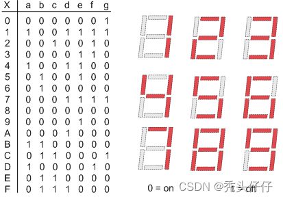
数码管显示
module B_To_7Seg(
	input [3:0] data_in,
	output reg [7:0] data_out
	);
	always @ (data_in)
		case(data_in)
			4'b0000:data_out = 8'b00000011;
			4'b0001:data_out = 8'b10011111;
			4'b0010:data_out = 8'b00100101;
			4'b0011:data_out = 8'b00001101;
			4'b0100:data_out = 8'b10011001;
			4'b0101:data_out = 8'b01001001;
			4'b0110:data_out = 8'b01000001;
			4'b0111:data_out = 8'b00011111;
			4'b1000:data_out = 8'b00000001;
			4'b1001:data_out = 8'b00001001;
			4'b1010:data_out = 8'b00010001;
			4'b1011:data_out = 8'b11000001;
			4'b1100:data_out = 8'b01100011;
			4'b1101:data_out = 8'b10000101;
			4'b1110:data_out = 8'b01100001;
			4'b1111:data_out = 8'b01110001;
			default:data_out = 8'bx;
		endcase
endmodule
- testbench
module B_To_7Seg_tb;
   reg [3:0] b_num;
   wire      oa;
   wire      ob;
   wire      oc;
   wire      od;
   wire      oe;
   wire      of;
   wire      og;

   B_To_7Seg u1(b_num,oa,ob,oc,od,oe,of,og);

   initial
       b_num=0000;
   always #10 b_num=b_num+1;
endmodule
整合实现
- 顶层模块
module topp;
	reg clk,reset,load;
	wire [31:0] count;
	wire [7:0] data_out1,data_out2,data_out3,data_out4,data_out5,data_out6,data_out7,data_out8;
	A32_bit u1(count,clk,reset,load);
	B_To_7Seg uu1(count[3:0],data_out1);
	B_To_7Seg uu2(count[7:4],data_out2);
	B_To_7Seg uu3(count[11:8],data_out3);
	B_To_7Seg uu4(count[15:12],data_out4);
	B_To_7Seg uu5(count[19:16],data_out5);
	B_To_7Seg uu6(count[23:20],data_out6);
	B_To_7Seg uu7(count[27:24],data_out7);
	B_To_7Seg uu8(count[31:28],data_out8);
	always #5 clk = ~clk;
	initial begin
		clk = 0;
		reset = 0;
		load = 1;
		#10 reset = ~reset;
		#100 load = ~load;
	end
endmodule


