eNSP 配置OSPF
一、子网划分
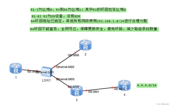
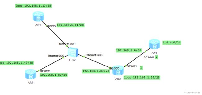
按需求,区域0可以汇总成一个网段以减少路由表条目,而区域1只有一个网段需要添加到路由表
划分如下
此处列举R1的配置
[r1]int loop 1
[r1-LoopBack1]ip ad 192.168.1.17 28
[r1-LoopBack1]int g0/0/0
[r1-GigabitEthernet0/0/0]ip ad 192.168.1.81 28
Jul 12 2022 22:35:53-08:00 r1 %%01IFNET/4/LINK_STATE(l)[0]:The line protocol IP on the interface GigabitEthernet0/0/0 has entered the UP state.
二、启用OSPF
R1 R2
[r1]ospf 1 router-id 1.1.1.1
***启动时可以定义进程号、RID;默认进程1,RID--格式为IPV4地址,全网唯一
[r1-ospf-1]area 0
***划分到区域0
[r1-ospf-1-area-0.0.0.0]network 192.168.1.81 0.0.0.0
[r1-ospf-1-area-0.0.0.0]network 192.168.1.17 0.0.0.0
***ospf在宣告时,需要使用反掩码,来匹配宣告的地址范围
***被选中接口的拓扑信息可以共享给邻接


[r2]ospf 1 router-id 2.2.2.2
[r2-ospf-1]area 0
[r2-ospf-1-area-0.0.0.0]netwo 192.168.1.49 0.0.0.0
[r2-ospf-1-area-0.0.0.0]netwo 192.168.1.83 0.0.0.0
R3
[r3]ospf 1 ro 3.3.3.3
[r3-ospf-1]a
[r3-ospf-1]area 0
[r3-ospf-1-area-0.0.0.0]net
[r3-ospf-1-area-0.0.0.0]network 192.168.1.82 0.0.0.0
[r3-ospf-1-area-0.0.0.0]network 192.168.1.33 0.0.0.0
***宣告区域0内的接口
[r3-ospf-1-area-0.0.0.0]q
[r3-ospf-1]ar
[r3-ospf-1]area 1
[r3-ospf-1-area-0.0.0.1]net
[r3-ospf-1-area-0.0.0.1]network 192.168.1.1 0.0.0.0
***宣告区域1内的接口
R4
[r4]ospf 1 router-id 5.5.5.5
[r4-ospf-1]area 1
[r4-ospf-1-area-0.0.0.1]network 192.168.1.2 0.0.0.0
三、设置DR设备
要求R1-R3中,R3为DR设备,且R1-R3中没有BDR设备。
选举DR/BDR的规则为:
1.先比较该网段所有参选设备接口的优先级,越大越优;
默认优先级为1;取值范围0-255,0标识不参选
2.若所有参选者优先级相同,比较参选设备的RID,数值大优
所以在区域0中R3是DR(Master),R2是BDR(Master)
选举DR/BDR默认优先级为1,所以将R1、R2的优先级设置为0,将R3的优先级设置为2;
ospf的选举是非抢占性的;故在修改完优先级后,需要所有路由器重启OSPF进程。
此处列举R3的配置
[r3]interface GigabitEthernet 0/0/0
[r3-GigabitEthernet0/0/0]ospf dr-priority  2  修改接口优先级

reset ospf process   重启ospf进程
Warning: The OSPF process will be reset. Continue? [Y/N]:y
此时再查看R3的ospf邻居信息
[r3]display ospf peer

         OSPF Process 1 with Router ID 3.3.3.3
                 Neighbors

 Area 0.0.0.0 interface 192.168.1.82(GigabitEthernet0/0/0)'s neighbors
 Router ID: 1.1.1.1          Address: 192.168.1.81
   State: Full  Mode:Nbr is  Slave  Priority: 0
   DR: 192.168.1.82  BDR: None   MTU: 0
   Dead timer due in 33  sec
   Retrans timer interval: 5
   Neighbor is up for 00:02:18
   Authentication Sequence: [ 0 ]

 Router ID: 2.2.2.2          Address: 192.168.1.83
   State: Full  Mode:Nbr is  Slave  Priority: 0
   DR: 192.168.1.82  BDR: None   MTU: 0
   Dead timer due in 33  sec
   Retrans timer interval: 5
   Neighbor is up for 00:02:28
   Authentication Sequence: [ 0 ]

                 Neighbors

 Area 0.0.0.1 interface 192.168.1.1(GigabitEthernet0/0/1)'s neighbors
 Router ID: 5.5.5.5          Address: 192.168.1.2
   State: Full  Mode:Nbr is  Master  Priority: 1
   DR: 192.168.1.2  BDR: 192.168.1.1  MTU: 0
   Dead timer due in 35  sec
   Retrans timer interval: 5
   Neighbor is up for 00:03:04
   Authentication Sequence: [ 0 ]
此时区域0已经没有了BDR
三、OSPF的区域汇总
OSPF协议不支持接口汇总;只能在ABR上将a区域拓扑计算所得路由,共享给B区域时进行汇总
分析拓扑图,得知R3是区域0到区域1的ABR(区域边界路由器),则在R3中进行配置
则R3的配置如下
[r3]ospf
[r3-ospf-1]area 0
***选中区域0
[r3-ospf-1-area-0.0.0.0]abr-summary 192.168.1.0 255.255.255.128
***R3为一台连接区域0和其他区域的ABR;
***以上操作为,R2将通过区域0学习到的拓扑计算所得的路由,
***传递给其他区域时进行汇总,汇总网段192.168.1.0/25
四、OSPF缺省路由配置
要求不能宣告R4的环回且使得全网可达,则需要配置缺省路由。
边界路由器上配置后,将自动向内网下放一条缺省路由,之后内网设备将自动生成缺省路由指向边界。
分析拓扑图,得知R4为该内网的边界路由。
配置如下
[r4]ospf 1
[r4-ospf-1]default-route-advertise always
五、OSPF的接口认证
要求全网可达的同时,路由器之间更新安全。
则给在直连邻居或邻接的接口上配置,保障更新的安全。
而区域0中R1-R3都是直连邻居或邻接的接口,所以认证码要一致
而区域1中只要求R3和R4之间认证码相同
此处区域0中的配置
[r1-GigabitEthernet0/0/0]ospf authentication-mode md5  1 cipher 123
***md5后的1代表ospf的进程号
[r2-GigabitEthernet0/0/0]ospf authentication-mode md5  1 cipher 123
[r3-GigabitEthernet0/0/0]ospf authentication-mode md5  1 cipher 123
区域1中的配置
[r3-GigabitEthernet0/0/1]ospf authentication-mode md5  1 cipher 124
[r4-GigabitEthernet0/0/0]ospf authentication-mode md5  1 cipher 124
六、测试
用R1 ping 其他三个路由器的环回 全部能ping通
[r1]ping 4.4.4.1
  PING 4.4.4.1: 56  data bytes, press CTRL_C to break
    Reply from 4.4.4.1: bytes=56 Sequence=1 ttl=254 time=50 ms
    Reply from 4.4.4.1: bytes=56 Sequence=2 ttl=254 time=70 ms
    Reply from 4.4.4.1: bytes=56 Sequence=3 ttl=254 time=40 ms
    Reply from 4.4.4.1: bytes=56 Sequence=4 ttl=254 time=40 ms
    Reply from 4.4.4.1: bytes=56 Sequence=5 ttl=254 time=50 ms

  --- 4.4.4.1 ping statistics ---
    5 packet(s) transmitted
    5 packet(s) received
    0.00% packet loss
    round-trip min/avg/max = 40/50/70 ms


[r1]ping 192.168.1.49
  PING 192.168.1.49: 56  data bytes, press CTRL_C to break
    Reply from 192.168.1.49: bytes=56 Sequence=1 ttl=255 time=40 ms
    Reply from 192.168.1.49: bytes=56 Sequence=2 ttl=255 time=60 ms
    Reply from 192.168.1.49: bytes=56 Sequence=3 ttl=255 time=60 ms
    Reply from 192.168.1.49: bytes=56 Sequence=4 ttl=255 time=40 ms
    Reply from 192.168.1.49: bytes=56 Sequence=5 ttl=255 time=40 ms

  --- 192.168.1.49 ping statistics ---
    5 packet(s) transmitted
    5 packet(s) received
    0.00% packet loss
    round-trip min/avg/max = 40/48/60 ms


[r1]ping 192.168.1.82
  PING 192.168.1.82: 56  data bytes, press CTRL_C to break
    Reply from 192.168.1.82: bytes=56 Sequence=1 ttl=255 time=50 ms
    Reply from 192.168.1.82: bytes=56 Sequence=2 ttl=255 time=40 ms
    Reply from 192.168.1.82: bytes=56 Sequence=3 ttl=255 time=70 ms
    Reply from 192.168.1.82: bytes=56 Sequence=4 ttl=255 time=40 ms
    Reply from 192.168.1.82: bytes=56 Sequence=5 ttl=255 time=60 ms

  --- 192.168.1.82 ping statistics ---
    5 packet(s) transmitted
    5 packet(s) received
    0.00% packet loss
    round-trip min/avg/max = 40/52/70 ms

