五、基础初始化(init_sequence)
初始化序列数组
# < lib_arm\board.c >
init_fnc_t *init_sequence[] = {
board_init, /* basic board dependent setup */
timer_init, /* initialize timer */
env_init, /* initialize environment */
init_baudrate, /* initialze baudrate settings */
serial_init, /* serial communications setup */
console_init_f, /* stage 1 init of console */
display_banner, /* say that we are here */
dram_init, /* configure available RAM banks */
arm_pci_init,
display_dram_config,
NULL,
};
初始化函数
board_init(基础板级初始化)
# < board\vbird\mini2440\mini2440.c >
int board_init (void)
{
struct s3c24x0_clock_power * const clk_power = s3c24x0_get_base_clock_power();
struct s3c24x0_gpio * const gpio = s3c24x0_get_base_gpio();
/* to reduce PLL lock time, adjust the LOCKTIME register */
clk_power->LOCKTIME = 0xFFFFFF;
/* configure MPLL */
clk_power->MPLLCON = ((M_MDIV << 12) + (M_PDIV << 4) + M_SDIV);
/* some delay between MPLL and UPLL */
delay (4000);
/* configure UPLL */
clk_power->UPLLCON = ((U_M_MDIV << 12) + (U_M_PDIV << 4) + U_M_SDIV);
/* some delay between MPLL and UPLL */
delay (8000);
/* set up the I/O ports */
gpio->GPACON = 0x007FFFFF;
gpio->GPBCON = 0x00044555;
gpio->GPBUP = 0x000007FF;
gpio->GPCCON = 0xAAAAAAAA;
gpio->GPCUP = 0x0000FFFF;
gpio->GPDCON = 0xAAAAAAAA;
gpio->GPDUP = 0x0000FFFF;
gpio->GPECON = 0xAAAAAAAA;
gpio->GPEUP = 0x0000FFFF;
gpio->GPFCON = 0x000055AA;
gpio->GPFUP = 0x000000FF;
gpio->GPGCON = 0xFF95FFBA;
gpio->GPGUP = 0x0000FFFF;
gpio->GPHCON = 0x002AFAAA;
gpio->GPHUP = 0x000007FF;
/* arch number of SMDK2410-Board */
gd->bd->bi_arch_number = MACH_TYPE_MINI2440;
/* adress of boot parameters */
gd->bd->bi_boot_params = 0x30000100;
icache_enable();
dcache_enable();
return 0;
}
获取时钟设置结构体
# < include\s3c2410.h >
#define S3C24X0_CLOCK_POWER_BASE 0x4C000000
static inline struct s3c24x0_clock_power *s3c24x0_get_base_clock_power(void)
{
return (struct s3c24x0_clock_power *)S3C24X0_CLOCK_POWER_BASE;
}
说明:
LOCKTIME 0x4C000000 //MPLL设置之后频率不稳定影响FCLK,所有会将FCLK锁定一地段时间
MPLLCON 0x4C000004 //MPLL锁相环控制器,控制着FCLK的频率
UPLLCON 0x4C000008 //UPLL锁相环控制器,控制着UCKL频率,USB的时钟频率
CLKCON 0x4C00000C //不同模块的时钟使能控制器
CLKSLOW 0x4C000010
CLKDIVN 0x4C000014
CAMDIVN 0x4C000018
设置MPLL锁相环,将FCLK设置为406MHz
# < board\vbird\mini2440\mini2440.c >
#define M_MDIV 0x7F
#define M_PDIV 0x2
#define M_SDIV 0x1
clk_power->MPLLCON = ((M_MDIV << 12) + (M_PDIV << 4) + M_SDIV);
FCLK = (2*(7F+8)*12MHz)/( (4+2)*2^1 ) = 406MHz
设置UPLL锁相环
/* some delay between MPLL and UPLL */
delay (4000);
/* configure UPLL */
clk_power->UPLLCON = ((U_M_MDIV << 12) + (U_M_PDIV << 4) + U_M_SDIV);
/* some delay between MPLL and UPLL */
delay (8000);
GPIO初始化
/* set up the I/O ports */
gpio->GPACON = 0x007FFFFF;
gpio->GPBCON = 0x00044555;
gpio->GPBUP = 0x000007FF;
gpio->GPCCON = 0xAAAAAAAA;
gpio->GPCUP = 0x0000FFFF;
gpio->GPDCON = 0xAAAAAAAA;
gpio->GPDUP = 0x0000FFFF;
gpio->GPECON = 0xAAAAAAAA;
gpio->GPEUP = 0x0000FFFF;
gpio->GPFCON = 0x000055AA;
gpio->GPFUP = 0x000000FF;
gpio->GPGCON = 0xFF95FFBA;
gpio->GPGUP = 0x0000FFFF;
gpio->GPHCON = 0x002AFAAA;
gpio->GPHUP = 0x000007FF;
设置ArchNumber,后续内核引导也需要这个参数
gd->bd->bi_arch_number = MACH_TYPE_MINI2440;
说明:内核引导第二个参数会使用
# < lib_arm\bootm.c > - do_bootm_linux
void (*theKernel)(int zero, int arch, uint params); //第二个参数
设置uboot向内核传递参数的地址参数
gd->bd->bi_boot_params = 0x30000100;
iCache和dCache的使能(指令/数据高速缓存)
icache_enable();
dcache_enable();
说明:
CR_I:icache
CR_C:dcache
static void cache_enable(uint32_t cache_bit)
{
uint32_t reg;
reg = get_cr(); /* get control reg. */
cp_delay();
set_cr(reg | cache_bit);
}
static inline unsigned int get_cr(void)
{
unsigned int val;
asm("mrc p15, 0, %0, c1, c0, 0 @ get CR" : "=r" (val) : : "cc");
return val;
}
#define isb() __asm__ __volatile__ ("" : : : "memory")
static inline void set_cr(unsigned int val)
{
asm volatile("mcr p15, 0, %0, c1, c0, 0 @ set CR"
: : "r" (val) : "cc");
isb();
}
timer_init(定时器初始化)
int timer_init(void)
{
struct s3c24x0_timers *timers = s3c24x0_get_base_timers();
ulong tmr;
/* use PWM Timer 4 because it has no output */
/* prescaler for Timer 4 is 16 */
writel(0x0f00, &timers->TCFG0);
if (timer_load_val == 0) {
/*
* for 10 ms clock period @ PCLK with 4 bit divider = 1/2
* (default) and prescaler = 16. Should be 10390
* @33.25MHz and 15625 @ 50 MHz
*/
timer_load_val = get_PCLK() / (2 * 16 * 100);
timer_clk = get_PCLK() / (2 * 16);
}
/* load value for 10 ms timeout */
lastdec = timer_load_val;
writel(timer_load_val, &timers->TCNTB4);
/* auto load, manual update of Timer 4 */
tmr = (readl(&timers->TCON) & ~0x0700000) | 0x0600000;
writel(tmr, &timers->TCON);
/* auto load, start Timer 4 */
tmr = (tmr & ~0x0700000) | 0x0500000;
writel(tmr, &timers->TCON);
timestamp = 0;
return (0);
}
获取定时器设置结构体
#define S3C24X0_TIMER_BASE 0x51000000
static inline struct s3c24x0_timers *s3c24x0_get_base_timers(void)
{
return (struct s3c24x0_timers *)S3C24X0_TIMER_BASE;
}
struct s3c24x0_timers {
S3C24X0_REG32 TCFG0;
S3C24X0_REG32 TCFG1;
S3C24X0_REG32 TCON;
struct s3c24x0_timer ch[4];
S3C24X0_REG32 TCNTB4;
S3C24X0_REG32 TCNTO4;
};
struct s3c24x0_timer {
S3C24X0_REG32 TCNTB;
S3C24X0_REG32 TCMPB;
S3C24X0_REG32 TCNTO;
};
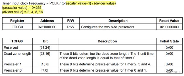
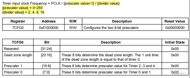
TCFG0 0x51000000 //定时器配置(配置两个8位预分频器)
TCFG1 0x51000004 //定时器配置(5个MUX和DMA模式选择)
TCON 0x51000008 //定时器控制器
TCNTB0 0x5100000C //定时器0计数缓冲区
TCMPB0 0x51000010 //定时器0比较缓冲区
TCNTO0 0x51000014 //定时器0计数观察寄存器
TCNTB1 0x51000018
TCMPB1 0x5100001C
TCNTO1 0x51000020
TCNTB2 0x51000024
TCMPB2 0x51000028
TCNTO2 0x5100002C
TCNTB3 0x51000030
TCMPB3 0x51000034
TCNTO3 0x51000038
TCNTB4 0x5100003C
TCNTO4 0x51000040
设置定时器配置0为0x0f00
writel(0x0f00, &timers->TCFG0);
Prescaler 1 = 0x0f
Prescaler 0 = 0x00
clock = 50MHz / (15+1) / (1/2)
设置定时器超时10ms
/* load value for 10 ms timeout */
lastdec = timer_load_val;
writel(timer_load_val, &timers->TCNTB4);
/* auto load, manual update of Timer 4 */
tmr = (readl(&timers->TCON) & ~0x0700000) | 0x0600000;
writel(tmr, &timers->TCON);
/* auto load, start Timer 4 */
tmr = (tmr & ~0x0700000) | 0x0500000;
writel(tmr, &timers->TCON);
timestamp = 0;
env_init(环境变量初始化)
init_baudrate(波特率初始化)
static int init_baudrate (void)
{
char tmp[64]; /* long enough for environment variables */
int i = getenv_r ("baudrate", tmp, sizeof (tmp));
gd->bd->bi_baudrate = gd->baudrate = (i > 0)
? (int) simple_strtoul (tmp, NULL, 10)
: CONFIG_BAUDRATE;
return (0);
}
serial_init(串口初始化)
int serial_init(void)
{
return serial_init_dev(UART_NR); //UART_NR = 0
}
struct s3c24x0_uart {
S3C24X0_REG32 ULCON;
S3C24X0_REG32 UCON;
S3C24X0_REG32 UFCON;
S3C24X0_REG32 UMCON;
S3C24X0_REG32 UTRSTAT;
S3C24X0_REG32 UERSTAT;
S3C24X0_REG32 UFSTAT;
S3C24X0_REG32 UMSTAT;
S3C24X0_REG8 UTXH;
S3C24X0_REG8 res1[3];
S3C24X0_REG8 URXH;
S3C24X0_REG8 res2[3];
S3C24X0_REG32 UBRDIV;
};
static int serial_init_dev(const int dev_index)
{
struct s3c24x0_uart *uart = s3c24x0_get_base_uart(dev_index); //dev_index = 0
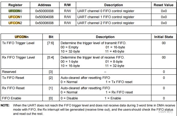
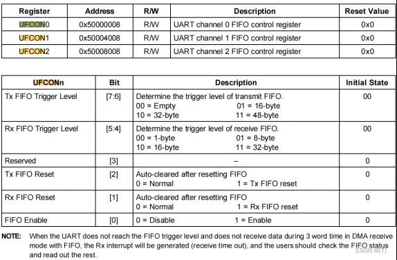
/* FIFO enable, Tx/Rx FIFO clear */
writel(0x07, &uart->UFCON); //使能FIFO
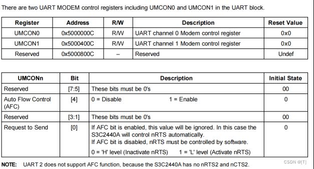
writel(0x0, &uart->UMCON); //取消使能自动流量控制
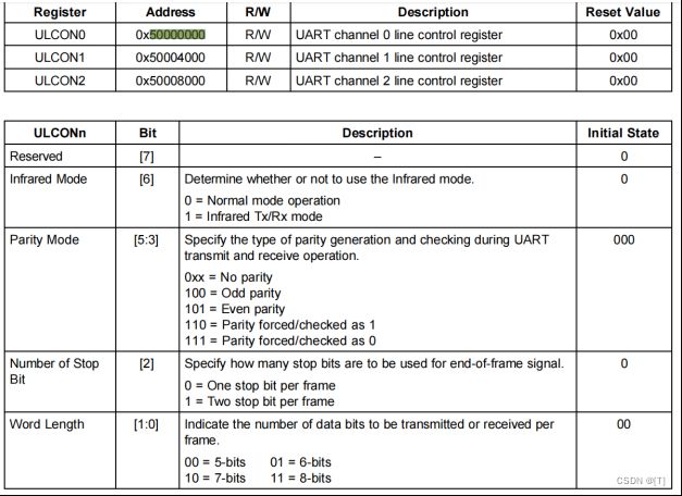
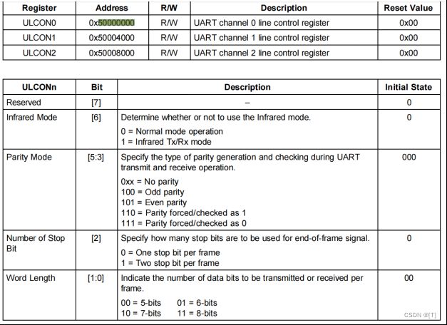
/* Normal,No parity,1 stop,8 bit */
writel(0x3, &uart->ULCON); // 0个停止位,8位数据
/*
* tx=level,rx=edge,disable timeout int.,enable rx error int.,
* normal,interrupt or polling
*/
writel(0x245, &uart->UCON);
_serial_setbrg(dev_index);
return (0);
}
#define S3C24X0_UART_BASE 0x50000000
static inline struct s3c24x0_uart *s3c24x0_get_base_uart(enum s3c24x0_uarts_nr n)
{
return (struct s3c24x0_uart *)(S3C24X0_UART_BASE + (n * 0x4000));
}
console_init_f(控制台初始化,第一阶段)
int console_init_f(void)
{
gd->have_console = 1;
return 0;
}
display_banner(打印信息,Uboot终端第一条信息)
static int display_banner (void)
{
printf ("\n\n%s\n\n", version_string);
debug ("U-Boot code: %08lX -> %08lX BSS: -> %08lX\n",
_armboot_start, _bss_start, _bss_end);
return (0);
}
const char version_string[] =
U_BOOT_VERSION" (" U_BOOT_DATE " - " U_BOOT_TIME ")"CONFIG_IDENT_STRING;
#define U_BOOT_VERSION "U-Boot 2009.11"
#define U_BOOT_DATE " 4月 24 2012"
#define U_BOOT_TIME "10:35:44"
![]()
dram_init(配置RAM块)
int dram_init (void)
{
gd->bd->bi_dram[0].start = PHYS_SDRAM_1;
gd->bd->bi_dram[0].size = PHYS_SDRAM_1_SIZE;
return 0;
}
#define PHYS_SDRAM_1 0x30000000 /* SDRAM Bank #1 */
#define PHYS_SDRAM_1_SIZE 0x04000000 /* 64 MB */
arm_pci_init(好像没调用)
display_dram_config(打印RAM配置,主要为大小)
static int display_dram_config (void)
{
int i;
ulong size = 0;
for (i=0; i size += gd->bd->bi_dram[i].size; } puts("DRAM: "); print_size(size, "\n"); return (0); } #define CONFIG_NR_DRAM_BANKS 1 /* we have 1 bank of DRAM */ 设置MPLL锁相环,将FCLK设置为406MHz # < board\vbird\mini2440\mini2440.c > #define M_MDIV 0x7F #define M_PDIV 0x2 #define M_SDIV 0x1 clk_power->MPLLCON = ((M_MDIV << 12) + (M_PDIV << 4) + M_SDIV); FCLK = (2*(7F+8)*12MHz)/( (4+2)*2^1 ) = 406MHz 设置UPLL锁相环 /* some delay between MPLL and UPLL */ delay (4000); /* configure UPLL */ clk_power->UPLLCON = ((U_M_MDIV << 12) + (U_M_PDIV << 4) + U_M_SDIV); /* some delay between MPLL and UPLL */ delay (8000); GPIO初始化 /* set up the I/O ports */ gpio->GPACON = 0x007FFFFF; gpio->GPBCON = 0x00044555; gpio->GPBUP = 0x000007FF; gpio->GPCCON = 0xAAAAAAAA; gpio->GPCUP = 0x0000FFFF; gpio->GPDCON = 0xAAAAAAAA; gpio->GPDUP = 0x0000FFFF; gpio->GPECON = 0xAAAAAAAA; gpio->GPEUP = 0x0000FFFF; gpio->GPFCON = 0x000055AA; gpio->GPFUP = 0x000000FF; gpio->GPGCON = 0xFF95FFBA; gpio->GPGUP = 0x0000FFFF; gpio->GPHCON = 0x002AFAAA; gpio->GPHUP = 0x000007FF; 设置ArchNumber,后续内核引导也需要这个参数 gd->bd->bi_arch_number = MACH_TYPE_MINI2440; 说明:内核引导第二个参数会使用 # < lib_arm\bootm.c > - do_bootm_linux void (*theKernel)(int zero, int arch, uint params); //第二个参数 设置uboot向内核传递参数的地址参数 gd->bd->bi_boot_params = 0x30000100; iCache和dCache的使能(指令/数据高速缓存) icache_enable(); dcache_enable(); 说明: CR_I:icache CR_C:dcache static void cache_enable(uint32_t cache_bit) { uint32_t reg; reg = get_cr(); /* get control reg. */ cp_delay(); set_cr(reg | cache_bit); } static inline unsigned int get_cr(void) { unsigned int val; asm("mrc p15, 0, %0, c1, c0, 0 @ get CR" : "=r" (val) : : "cc"); return val; } #define isb() __asm__ __volatile__ ("" : : : "memory") static inline void set_cr(unsigned int val) { asm volatile("mcr p15, 0, %0, c1, c0, 0 @ set CR" : : "r" (val) : "cc"); isb(); } timer_init(定时器初始化) int timer_init(void) { struct s3c24x0_timers *timers = s3c24x0_get_base_timers(); ulong tmr; /* use PWM Timer 4 because it has no output */ /* prescaler for Timer 4 is 16 */ writel(0x0f00, &timers->TCFG0); if (timer_load_val == 0) { /* * for 10 ms clock period @ PCLK with 4 bit divider = 1/2 * (default) and prescaler = 16. Should be 10390 * @33.25MHz and 15625 @ 50 MHz */ timer_load_val = get_PCLK() / (2 * 16 * 100); timer_clk = get_PCLK() / (2 * 16); } /* load value for 10 ms timeout */ lastdec = timer_load_val; writel(timer_load_val, &timers->TCNTB4); /* auto load, manual update of Timer 4 */ tmr = (readl(&timers->TCON) & ~0x0700000) | 0x0600000; writel(tmr, &timers->TCON); /* auto load, start Timer 4 */ tmr = (tmr & ~0x0700000) | 0x0500000; writel(tmr, &timers->TCON); timestamp = 0; return (0); } 获取定时器设置结构体 #define S3C24X0_TIMER_BASE 0x51000000 static inline struct s3c24x0_timers *s3c24x0_get_base_timers(void) { return (struct s3c24x0_timers *)S3C24X0_TIMER_BASE; } struct s3c24x0_timers { S3C24X0_REG32 TCFG0; S3C24X0_REG32 TCFG1; S3C24X0_REG32 TCON; struct s3c24x0_timer ch[4]; S3C24X0_REG32 TCNTB4; S3C24X0_REG32 TCNTO4; }; struct s3c24x0_timer { S3C24X0_REG32 TCNTB; S3C24X0_REG32 TCMPB; S3C24X0_REG32 TCNTO; }; TCFG0 0x51000000 //定时器配置(配置两个8位预分频器) TCFG1 0x51000004 //定时器配置(5个MUX和DMA模式选择) TCON 0x51000008 //定时器控制器 TCNTB0 0x5100000C //定时器0计数缓冲区 TCMPB0 0x51000010 //定时器0比较缓冲区 TCNTO0 0x51000014 //定时器0计数观察寄存器 TCNTB1 0x51000018 TCMPB1 0x5100001C TCNTO1 0x51000020 TCNTB2 0x51000024 TCMPB2 0x51000028 TCNTO2 0x5100002C TCNTB3 0x51000030 TCMPB3 0x51000034 TCNTO3 0x51000038 TCNTB4 0x5100003C TCNTO4 0x51000040 设置定时器配置0为0x0f00 writel(0x0f00, &timers->TCFG0); Prescaler 1 = 0x0f Prescaler 0 = 0x00 clock = 50MHz / (15+1) / (1/2) 设置定时器超时10ms /* load value for 10 ms timeout */ lastdec = timer_load_val; writel(timer_load_val, &timers->TCNTB4); /* auto load, manual update of Timer 4 */ tmr = (readl(&timers->TCON) & ~0x0700000) | 0x0600000; writel(tmr, &timers->TCON); /* auto load, start Timer 4 */ tmr = (tmr & ~0x0700000) | 0x0500000; writel(tmr, &timers->TCON); timestamp = 0; env_init(环境变量初始化) init_baudrate(波特率初始化) static int init_baudrate (void) { char tmp[64]; /* long enough for environment variables */ int i = getenv_r ("baudrate", tmp, sizeof (tmp)); gd->bd->bi_baudrate = gd->baudrate = (i > 0) ? (int) simple_strtoul (tmp, NULL, 10) : CONFIG_BAUDRATE; return (0); } serial_init(串口初始化) int serial_init(void) { return serial_init_dev(UART_NR); //UART_NR = 0 } struct s3c24x0_uart { S3C24X0_REG32 ULCON; S3C24X0_REG32 UCON; S3C24X0_REG32 UFCON; S3C24X0_REG32 UMCON; S3C24X0_REG32 UTRSTAT; S3C24X0_REG32 UERSTAT; S3C24X0_REG32 UFSTAT; S3C24X0_REG32 UMSTAT; S3C24X0_REG8 UTXH; S3C24X0_REG8 res1[3]; S3C24X0_REG8 URXH; S3C24X0_REG8 res2[3]; S3C24X0_REG32 UBRDIV; }; static int serial_init_dev(const int dev_index) { struct s3c24x0_uart *uart = s3c24x0_get_base_uart(dev_index); //dev_index = 0 /* FIFO enable, Tx/Rx FIFO clear */ writel(0x07, &uart->UFCON); //使能FIFO writel(0x0, &uart->UMCON); //取消使能自动流量控制 /* Normal,No parity,1 stop,8 bit */ writel(0x3, &uart->ULCON); // 0个停止位,8位数据 /* * tx=level,rx=edge,disable timeout int.,enable rx error int., * normal,interrupt or polling */ writel(0x245, &uart->UCON); _serial_setbrg(dev_index); return (0); } #define S3C24X0_UART_BASE 0x50000000 static inline struct s3c24x0_uart *s3c24x0_get_base_uart(enum s3c24x0_uarts_nr n) { return (struct s3c24x0_uart *)(S3C24X0_UART_BASE + (n * 0x4000)); } console_init_f(控制台初始化,第一阶段) int console_init_f(void) { gd->have_console = 1; return 0; } display_banner(打印信息,Uboot终端第一条信息) static int display_banner (void) { printf ("\n\n%s\n\n", version_string); debug ("U-Boot code: %08lX -> %08lX BSS: -> %08lX\n", _armboot_start, _bss_start, _bss_end); return (0); } const char version_string[] = U_BOOT_VERSION" (" U_BOOT_DATE " - " U_BOOT_TIME ")"CONFIG_IDENT_STRING; #define U_BOOT_VERSION "U-Boot 2009.11" #define U_BOOT_DATE " 4月 24 2012" #define U_BOOT_TIME "10:35:44" dram_init(配置RAM块) int dram_init (void) { gd->bd->bi_dram[0].start = PHYS_SDRAM_1; gd->bd->bi_dram[0].size = PHYS_SDRAM_1_SIZE; return 0; } #define PHYS_SDRAM_1 0x30000000 /* SDRAM Bank #1 */ #define PHYS_SDRAM_1_SIZE 0x04000000 /* 64 MB */ arm_pci_init(好像没调用) display_dram_config(打印RAM配置,主要为大小) static int display_dram_config (void) { int i; ulong size = 0; for (i=0; i size += gd->bd->bi_dram[i].size; } puts("DRAM: "); print_size(size, "\n"); return (0); } #define CONFIG_NR_DRAM_BANKS 1 /* we have 1 bank of DRAM */![]()


