树莓派4B通过UART外接ESP32C3--增加一个蓝牙HCI(推荐)
First step
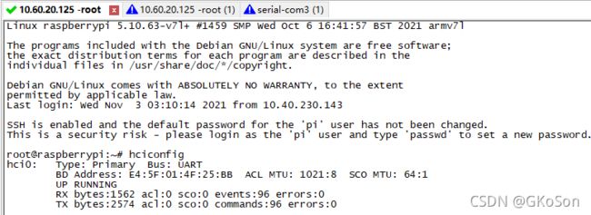
Let's say we have a brand new raspberry pie. Now turn it on.run hciconfig you will see like this
假设我们有一台全新的树莓派 现在开机启动 执行命令你会看到
root@raspberrypi:~# hciconfig
hci0: Type: Primary Bus: UART
BD Address: E4:5F:01:4F:25:BB ACL MTU: 1021:8 SCO MTU: 64:1
UP RUNNING
RX bytes:1562 acl:0 sco:0 events:96 errors:0
TX bytes:2574 acl:0 sco:0 commands:96 errors:0
This is the onboard Bluetooth of raspberry pie
这是树莓派的板载蓝牙
Step 2
在文件/boot/config.txt 的最后追加如下内容 随后reboot
Add the following contents at the end of the file / boot / config.txt Then reboot
dtoverlay=uart2
目的是使能树莓派的UART2 如果有2个以上的蓝牙模块就追加使能个更多的UART
The purpose is to enable UART2 of raspberry pie If there are more than 2 Bluetooth modules, more UARTS will be added
Hang the HCI interface through UART2, that is, AMA1, and execute the following command to see the new hci1, but now it is all 0
通过UART2也就是AMA1挂HCI接口出去 执行下面的命令 就看到新的HCI1 但是现在是全0
sudo btattach -N -B /dev/ttyAMA1 -S 115200
Step 3
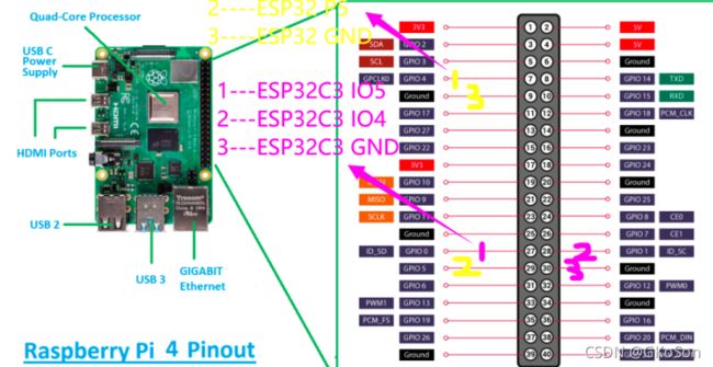
接线 下图紫色部分
UART2:
TXD2-->GPIO0
RXD2-->GPIO1
Step 4
固件准备
Firmware preparation
修改一点点
#define GPIO_UART_RTS_OUT (-1)
#define GPIO_UART_CTS_IN (-1)
源码
/*
   This example code is in the Public Domain (or CC0 licensed, at your option.)

   Unless required by applicable law or agreed to in writing, this
   software is distributed on an "AS IS" BASIS, WITHOUT WARRANTIES OR
   CONDITIONS OF ANY KIND, either express or implied.
*/

#include
#include "driver/periph_ctrl.h"
#include "driver/gpio.h"
#include "driver/uart.h"
#include "soc/lldesc.h"
#include "esp_private/gdma.h"
#include "hal/uhci_ll.h"
#include "esp_bt.h"
#include "esp_log.h"

static const char *tag = "UHCI";

#define UART_HCI_NUM       (1)

#define UART_RX_THRS       (120)

#define GPIO_UART_TXD_OUT  (4)
#define GPIO_UART_RXD_IN   (5)
#define GPIO_UART_RTS_OUT  (-1)
#define GPIO_UART_CTS_IN   (-1)

#define GPIO_OUTPUT_PIN_SEL  ((1ULL<pkt_thres.thrs = size;

    gdma_start(s_rx_channel, (intptr_t)(&uart_env.rx.link));
}

static IRAM_ATTR void hci_uart_tl_send_async(uint8_t *buf, uint32_t size, esp_bt_hci_tl_callback_t callback, void *arg)
{
    assert(buf != NULL);
    assert(size != 0);
    assert(callback != NULL);

    uart_env.tx.callback = callback;
    uart_env.tx.arg = arg;

    memset(&uart_env.tx.link, 0, sizeof(lldesc_t));
    uart_env.tx.link.length = size;
    uart_env.tx.link.buf = buf;
    uart_env.tx.link.eof = 1;

    gdma_start(s_tx_channel, (intptr_t)(&uart_env.tx.link));
}

static void hci_uart_tl_flow_on(void)
{
}

static bool hci_uart_tl_flow_off(void)
{
    return true;
}

static void hci_uart_tl_finish_transfers(void)
{
}

static IRAM_ATTR bool hci_uart_tl_rx_eof_callback(gdma_channel_handle_t dma_chan, gdma_event_data_t *event_data, void *user_data)
{
    assert(dma_chan == s_rx_channel);
    assert(uart_env.rx.callback != NULL);
    esp_bt_hci_tl_callback_t callback = uart_env.rx.callback;
    void *arg = uart_env.rx.arg;

    // clear callback pointer
    uart_env.rx.callback = NULL;
    uart_env.rx.arg = NULL;

    // call handler
    callback(arg, ESP_BT_HCI_TL_STATUS_OK);

    // send notification to Bluetooth Controller task
    esp_bt_h4tl_eif_io_event_notify(1);

    return true;
}

static IRAM_ATTR bool hci_uart_tl_tx_eof_callback(gdma_channel_handle_t dma_chan, gdma_event_data_t *event_data, void *user_data)
{
    assert(dma_chan == s_tx_channel);
    assert(uart_env.tx.callback != NULL);
    esp_bt_hci_tl_callback_t callback = uart_env.tx.callback;
    void *arg = uart_env.tx.arg;

    // clear callback pointer
    uart_env.tx.callback = NULL;
    uart_env.tx.arg = NULL;

    // call handler
    callback(arg, ESP_BT_HCI_TL_STATUS_OK);

    // send notification to Bluetooth Controller task
    esp_bt_h4tl_eif_io_event_notify(1);

    return true;
}

static void uart_gpio_set(void)
{
    gpio_config_t io_output_conf = {
        .intr_type = GPIO_PIN_INTR_DISABLE,    //disable interrupt
        .mode = GPIO_MODE_OUTPUT,    // output mode
        .pin_bit_mask = GPIO_OUTPUT_PIN_SEL,    // bit mask of the output pins
        .pull_down_en = 0,    // disable pull-down mode
        .pull_up_en = 0,    // disable pull-up mode
    };
    gpio_config(&io_output_conf);

    gpio_config_t io_input_conf = {
        .intr_type = GPIO_PIN_INTR_DISABLE,    //disable interrupt
        .mode = GPIO_MODE_INPUT,    // input mode
        .pin_bit_mask = GPIO_INPUT_PIN_SEL,  // bit mask of the input pins
        .pull_down_en = 0,    // disable pull-down mode
        .pull_up_en = 0,    // disable pull-down mode
    };
    gpio_config(&io_input_conf);

    uart_set_pin(UART_HCI_NUM, GPIO_UART_TXD_OUT, GPIO_UART_RXD_IN, GPIO_UART_RTS_OUT, GPIO_UART_CTS_IN);
}

void uhci_uart_install(void)
{
    periph_module_enable(PERIPH_UHCI0_MODULE);
    periph_module_reset(PERIPH_UHCI0_MODULE);

    periph_module_enable(PERIPH_UART1_MODULE);
    periph_module_reset(PERIPH_UART1_MODULE);

    uart_gpio_set();

    // configure UART1
    uart_config_t uart_config = {
        .baud_rate = CONFIG_EXAMPLE_HCI_UART_BAUDRATE,
        .data_bits = UART_DATA_8_BITS,
        .parity = UART_PARITY_DISABLE,
        .stop_bits = UART_STOP_BITS_1,
        .flow_ctrl = UART_HW_FLOWCTRL_CTS_RTS,
        .rx_flow_ctrl_thresh = UART_RX_THRS,
        .source_clk = UART_SCLK_APB,
    };
    ESP_ERROR_CHECK(uart_param_config(UART_HCI_NUM, &uart_config));

    // install DMA driver
    gdma_channel_alloc_config_t tx_channel_config = {
        .flags.reserve_sibling = 1,
        .direction = GDMA_CHANNEL_DIRECTION_TX,
    };
    ESP_ERROR_CHECK(gdma_new_channel(&tx_channel_config, &s_tx_channel));
    gdma_channel_alloc_config_t rx_channel_config = {
        .direction = GDMA_CHANNEL_DIRECTION_RX,
        .sibling_chan = s_tx_channel,
    };
    ESP_ERROR_CHECK(gdma_new_channel(&rx_channel_config, &s_rx_channel));

    gdma_connect(s_tx_channel, GDMA_MAKE_TRIGGER(GDMA_TRIG_PERIPH_UART, 0));
    gdma_connect(s_rx_channel, GDMA_MAKE_TRIGGER(GDMA_TRIG_PERIPH_UART, 0));

    gdma_strategy_config_t strategy_config = {
        .auto_update_desc = false,
        .owner_check = false
    };
    gdma_apply_strategy(s_tx_channel, &strategy_config);
    gdma_apply_strategy(s_rx_channel, &strategy_config);

    gdma_rx_event_callbacks_t rx_cbs = {
        .on_recv_eof = hci_uart_tl_rx_eof_callback
    };
    gdma_register_rx_event_callbacks(s_rx_channel, &rx_cbs, NULL);

    gdma_tx_event_callbacks_t tx_cbs = {
        .on_trans_eof = hci_uart_tl_tx_eof_callback
    };
    gdma_register_tx_event_callbacks(s_tx_channel, &tx_cbs, NULL);

    // configure UHCI
    uhci_ll_init(s_uhci_hw);
    uhci_ll_set_eof_mode(s_uhci_hw, UHCI_RX_LEN_EOF);
    // disable software flow control
    s_uhci_hw->escape_conf.val = 0;
    uhci_ll_attach_uart_port(s_uhci_hw, 1);
}


void app_main(void)
{
    esp_err_t ret;

    uhci_uart_install();

    esp_bt_controller_config_t bt_cfg = BT_CONTROLLER_INIT_CONFIG_DEFAULT();
    bt_cfg.hci_tl_funcs = &s_hci_uart_tl_funcs;

    ret = esp_bt_controller_init(&bt_cfg);
    if (ret != ESP_OK) {
        ESP_LOGE(tag, "Bluetooth Controller initialize failed: %s", esp_err_to_name(ret));
        return;
    }

    ret = esp_bt_controller_enable(ESP_BT_MODE_BLE);
    if (ret != ESP_OK) {
        ESP_LOGE(tag, "Bluetooth Controller initialize failed: %s", esp_err_to_name(ret));
        return;
    }

    ESP_LOGI(tag, "HCI messages can be communicated over UART%d: \n"
             "--PINs: TxD %d, RxD %d, RTS %d, CTS %d\n"
             "--Baudrate: %d", UART_HCI_NUM,
             GPIO_UART_TXD_OUT, GPIO_UART_RXD_IN, GPIO_UART_RTS_OUT, GPIO_UART_CTS_IN,
             CONFIG_EXAMPLE_HCI_UART_BAUDRATE);
}
cp.bat
copy "D:\A-ESP-IDF\examples\bluetooth\hci\controller_hci_uart_esp32c3\build\bootloader\bootloader.bin"           "C:\Users\Koson.Gong\3D Objects\ESP32C3-CSDN\bootloader.bin"
copy "D:\A-ESP-IDF\examples\bluetooth\hci\controller_hci_uart_esp32c3\build\partition_table\partition-table.bin" "C:\Users\Koson.Gong\3D Objects\ESP32C3-CSDN\partition-table.bin"
copy "D:\A-ESP-IDF\examples\bluetooth\hci\controller_hci_uart_esp32c3\build\controller_hci_uart_demo.bin"         "C:\Users\Koson.Gong\3D Objects\ESP32C3-CSDN\app.bin"
根据IDF最后的提示可以用工具烧录
esptool.py esp32c3 -p COM15 -b 460800
--before=default_reset
--after=hard_reset write_flash
--flash_mode dio
--flash_freq 80m
--flash_size 2MB
0x0 bootloader/bootloader.bin
0x10000 controller_hci_uart_demo.bin
0x8000 partition_table/partition-table.bin
工具
D:\BaiduNetdiskDownload\flash_download_tools_v3.4.9.2_1 --不可以
D:\TSBrowserDownloads\flash_download_tool_3.9.0_0\flash_download_tool_3.9.0--可以
+++++++++增加复位特征+++++++++++++
结论:
正常工作中 下电ESP32或者移除ESP32
会发生程序复位
复位以后程序运行 表现为一直扫描
如果重新上电或者连接ESP32 也是一样 一直扫描
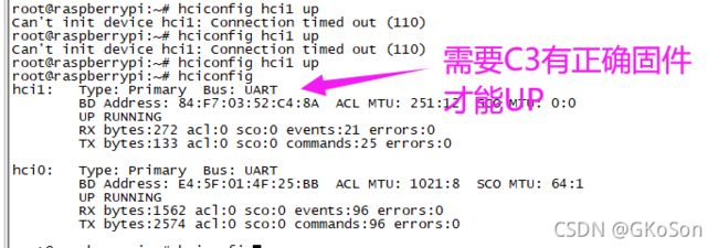
通过软件 hciconfig hci1 up不行
手动硬件复位一次ESP32 也不行
需要 手动复位 在UP
继续安装工具 利用烧录工具复位 = 板子硬件复位按键
sudo apt-get install python-pip
pip install esptool
esptool.py chip_id
效果也是一样的
在程序复位之前 已经连接ESP32则 恢复正常
在恢复复位以后 连接ESP32 看到一直在scan 执行esptool.py chip_id + UP 恢复正常
复位ESP32的办法1--下店上电 2--开发板按键 3--esptool.py chip_id因为刚刚好我们满足这个条件 假装去烧写的 其实就是复位一下 有LOG
