【百问网智能家居---基于单片机最小系统STM32F103C8T6_MINI的入门学习】
本人工作之余自学,该博客是为了记录学习过程,以及一些心得。内容如有出错,欢迎大家纠正,谢谢。
单片机时钟
1、单片机系统中必定有时钟,且在高级的单片机系统,存在不同频率的时钟;
2、时钟的本质就是同步(军训口号),在计算机系统中,时钟脉冲每产生一次,就推动处理器执行一下指令;时钟的频率越高(即口号的频率越快),CPU的执行效率就越快。但是,每个芯片的每个芯片在设计时,都会有时钟频率的设计上线,比如STM32F103C8T6的时钟上线就是72MHz;
3、芯片运行的时钟频率越高,芯片处理的速度越快,但同时功耗也越高。为了功耗和性能兼顾,微处理器一般有多个时钟源,同时还将时钟分频为多个大小,适配不同需求的外设。所以在一些复杂的系统中,时钟系统支持时钟的分频与倍频,以及开关部分时钟的功能,以便于适合各种要求的外设选取适合的时钟。
STM32时钟树

1、 HSI(High Speed Internal clock signal):是内部的高速时钟信号,频率8MHz。因为是内部提供,可以降低成本,缺点是精度较差。
2、 HSE(High Speed External clock signal): 是外部的高速时钟信号,需要外部电路晶振,输入频率范围要求为4-16MHz。因为需要外部电路提供,成本会增加,但精度较好。
3、 LSE(Low Speed External clock signal): 是外部的低速时钟信号,需要外部电路晶振,输入频率范围要求为32.768KHz。 一般用于RTC实时时钟。
4、 LSI(Low Speed Internal clock signal):是内部的低速RC振荡器,频率40KHz。一般用于看门狗、 RTC实时时钟等。
实例一:结合STM32CubeMX 分析时钟系统
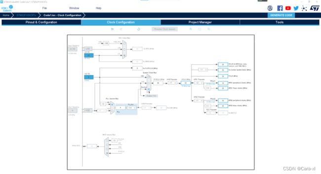
1、 点击时钟配置Clock Configuration,可STM32的时钟系统,其中LSI和HIS表示的是内部的低速和高速时钟,且是固定不能修改的。
2、 HSE和LSE在芯片的边界上存在连接引脚,需要外部电路来提供,而在灰色显示的情况下,需要配置配置好芯片的晶振功能引脚。
3、 参考电路原理图,再打开引脚配置,点击System Core的RCC进行时钟配置,即时钟使能。
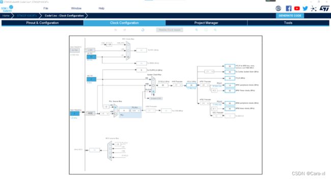
上图时钟树可以分为左右两个部分,左边为时钟源的选择和配置,右边为为各种配置时钟(AHB bus、核心、内存、DMA、系统时钟、APB1和APB2总线—各种外设)。APB1操作速度限于36MHz, APB2操作于全速(最高72MHz)。
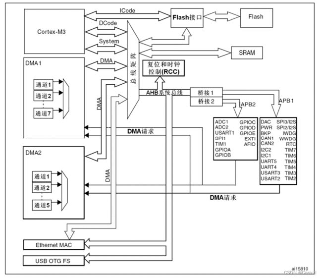
4、 生成代码
点击SystemClock_Config();函数查看时钟配置函数,分为两部分,一部分是时钟源配置,一个是总线时钟配置。以后再使用GPIO,只需要GPIO部分时钟使能就可以了,即再单独设置具外设的时钟使能。
void SystemClock_Config(void)
{
  RCC_OscInitTypeDef RCC_OscInitStruct = {0};
  RCC_ClkInitTypeDef RCC_ClkInitStruct = {0};

  /** Initializes the RCC Oscillators according to the specified parameters
  * in the RCC_OscInitTypeDef structure.
  */
  RCC_OscInitStruct.OscillatorType = RCC_OSCILLATORTYPE_HSE;
  RCC_OscInitStruct.HSEState = RCC_HSE_BYPASS;
  RCC_OscInitStruct.HSEPredivValue = RCC_HSE_PREDIV_DIV1;
  RCC_OscInitStruct.HSIState = RCC_HSI_ON;
  RCC_OscInitStruct.PLL.PLLState = RCC_PLL_ON;
  RCC_OscInitStruct.PLL.PLLSource = RCC_PLLSOURCE_HSE;
  RCC_OscInitStruct.PLL.PLLMUL = RCC_PLL_MUL9;
  if (HAL_RCC_OscConfig(&RCC_OscInitStruct) != HAL_OK)
  {
    Error_Handler();
  }
  /** Initializes the CPU, AHB and APB buses clocks
  */
  RCC_ClkInitStruct.ClockType = RCC_CLOCKTYPE_HCLK|RCC_CLOCKTYPE_SYSCLK
                              |RCC_CLOCKTYPE_PCLK1|RCC_CLOCKTYPE_PCLK2;
  RCC_ClkInitStruct.SYSCLKSource = RCC_SYSCLKSOURCE_PLLCLK;
  RCC_ClkInitStruct.AHBCLKDivider = RCC_SYSCLK_DIV1;
  RCC_ClkInitStruct.APB1CLKDivider = RCC_HCLK_DIV2;
  RCC_ClkInitStruct.APB2CLKDivider = RCC_HCLK_DIV1;

  if (HAL_RCC_ClockConfig(&RCC_ClkInitStruct, FLASH_LATENCY_2) != HAL_OK)
  {
    Error_Handler();
  }
}
定义了两个结构体,第一个是描述内外晶振配置结构体的定义:
/**
  * @brief  RCC Internal/External Oscillator (HSE, HSI, LSE and LSI) configuration structure definition
  */
typedef struct
{
  uint32_t OscillatorType;       /*!< The oscillators to be configured.
                                       This parameter can be a value of @ref RCC_Oscillator_Type */

#if defined(STM32F105xC) || defined(STM32F107xC)
  uint32_t Prediv1Source;       /*!<  The Prediv1 source value.
                                       This parameter can be a value of @ref RCCEx_Prediv1_Source */
#endif /* STM32F105xC || STM32F107xC */

  uint32_t HSEState;              /*!< The new state of the HSE.
                                       This parameter can be a value of @ref RCC_HSE_Config */

  uint32_t HSEPredivValue;       /*!<  The Prediv1 factor value (named PREDIV1 or PLLXTPRE in RM)
                                       This parameter can be a value of @ref RCCEx_Prediv1_Factor */

  uint32_t LSEState;              /*!<  The new state of the LSE.
                                        This parameter can be a value of @ref RCC_LSE_Config */

  uint32_t HSIState;              /*!< The new state of the HSI.
                                       This parameter can be a value of @ref RCC_HSI_Config */

  uint32_t HSICalibrationValue;   /*!< The HSI calibration trimming value (default is RCC_HSICALIBRATION_DEFAULT).
                                       This parameter must be a number between Min_Data = 0x00 and Max_Data = 0x1F */

  uint32_t LSIState;              /*!<  The new state of the LSI.
                                        This parameter can be a value of @ref RCC_LSI_Config */

  RCC_PLLInitTypeDef PLL;         /*!< PLL structure parameters */

#if defined(STM32F105xC) || defined(STM32F107xC)
  RCC_PLL2InitTypeDef PLL2;         /*!< PLL2 structure parameters */
#endif /* STM32F105xC || STM32F107xC */
} RCC_OscInitTypeDef;
第二个为系统AHB和APB总线配置结构体的定义:
/**
  * @brief  RCC System, AHB and APB busses clock configuration structure definition
  */
typedef struct
{
  uint32_t ClockType;             /*!< The clock to be configured.
                                       This parameter can be a value of @ref RCC_System_Clock_Type */

  uint32_t SYSCLKSource;          /*!< The clock source (SYSCLKS) used as system clock.
                                       This parameter can be a value of @ref RCC_System_Clock_Source */

  uint32_t AHBCLKDivider;         /*!< The AHB clock (HCLK) divider. This clock is derived from the system clock (SYSCLK).
                                       This parameter can be a value of @ref RCC_AHB_Clock_Source */

  uint32_t APB1CLKDivider;        /*!< The APB1 clock (PCLK1) divider. This clock is derived from the AHB clock (HCLK).
                                       This parameter can be a value of @ref RCC_APB1_APB2_Clock_Source */

  uint32_t APB2CLKDivider;        /*!< The APB2 clock (PCLK2) divider. This clock is derived from the AHB clock (HCLK).
                                       This parameter can be a value of @ref RCC_APB1_APB2_Clock_Source */
} RCC_ClkInitTypeDef;
STM32的GPIO
每个GPI/O端口有两个32位配置寄存器(GPIOx_CRL, GPIOx_CRH),两个32位数据寄存器(GPIOx_IDR和GPIOx_ODR),一个32位置位/复位寄存器(GPIOx_BSRR),一个16位复位寄存器(GPIOx_BRR)和一个32位锁定寄存器(GPIOx_LCKR)。
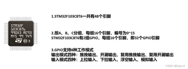
每个I/O端口位可以自由编程,然而I/0端口寄存器必须按32位字被访问(不允许半字或字节访问)。 GPIOx_BSRR和GPIOx_BRR寄存器允许对任何GPIO寄存器的读/更改的独立访问;这样,在读和更改访问之间产生IRQ时不会发生危险。
I/O端口位的基本结构
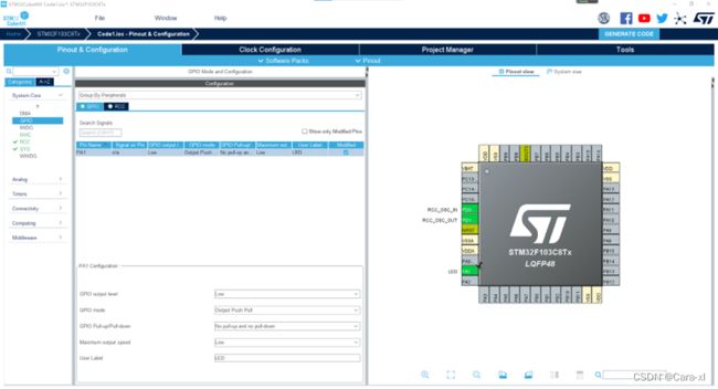
实例一:点亮一个LED灯
配置GPIO
生成代码
1、点击 MX_GPIO_Init();函数,查看GPIO初始化。
void MX_GPIO_Init(void)
{

  GPIO_InitTypeDef GPIO_InitStruct = {0};

  /* GPIO Ports Clock Enable */
  __HAL_RCC_GPIOD_CLK_ENABLE();
  __HAL_RCC_GPIOA_CLK_ENABLE();

  /*Configure GPIO pin Output Level */
  HAL_GPIO_WritePin(LED_GPIO_Port, LED_Pin, GPIO_PIN_RESET);

  /*Configure GPIO pin : PtPin */
  GPIO_InitStruct.Pin = LED_Pin;
  GPIO_InitStruct.Mode = GPIO_MODE_OUTPUT_PP;
  GPIO_InitStruct.Pull = GPIO_NOPULL;
  GPIO_InitStruct.Speed = GPIO_SPEED_FREQ_LOW;
  HAL_GPIO_Init(LED_GPIO_Port, &GPIO_InitStruct);

}
GPIO的初始化,这些都由STM32CubeMX生成提供,我们只需要在主函数里,使用HAL库提供的函数,进行对应的控制逻辑即可。GPIO最主要的就是输出。
while (1)
  {
    /* USER CODE END WHILE */

    /* USER CODE BEGIN 3 */
	HAL_GPIO_WritePin(GPIOA, GPIO_PIN_1, GPIO_PIN_RESET);
	HAL_Delay(1000);
	HAL_GPIO_WritePin(GPIOA, GPIO_PIN_1, GPIO_PIN_SET);
	HAL_Delay(1000);
  }
  /* USER CODE END 3 */
}
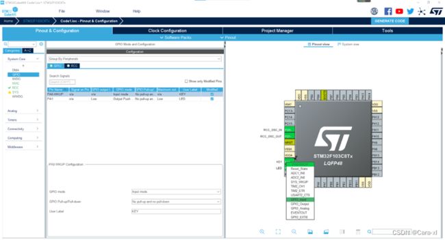
实例二:用户按键—GPIO输入

可见,在没有按键按下的时候,电源3.3V通过一个电阻接到MCU的PA0,此时MCU的PA0就是3.3V的高电平。当按键按下的时候,PA0相当于直接接到了GND,PA0就是底电平。由此MCU就可以通过读取对应引脚的电平值,来得知按键的一个状态。
由于常用的按键为机械触点式按键,会纯在机械抖动,导致一些高低电平反复出现。这些高低电平会被识别为多次的按键,从而导致误判,所以要进行消陡处理。
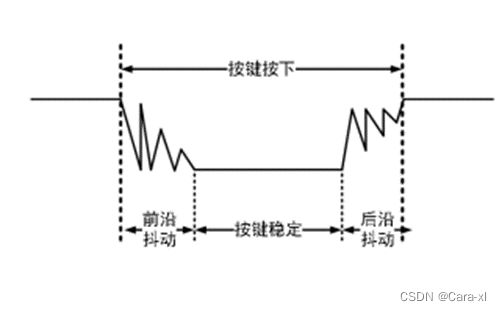
按键消抖,分为硬件消抖和软件消抖,硬件消抖在按键回路装一个电容,软件处理主要依据抖动时间在510ms,即延时510ms读取。
1、配置GPIO
2、主逻辑函数
  while (1)
  {
    /* USER CODE END WHILE */

//闪烁
//	HAL_GPIO_WritePin(GPIOA, GPIO_PIN_1, GPIO_PIN_RESET);
//	HAL_Delay(1000);
//	HAL_GPIO_WritePin(GPIOA, GPIO_PIN_1, GPIO_PIN_SET);
//	HAL_Delay(1000);


//按下按键灯亮
	if (0 == HAL_GPIO_ReadPin(KEY_GPIO_Port, KEY_Pin)) //如果按键引脚为低电平
	{
		HAL_Delay(8);  //去抖延时
		if (0 == HAL_GPIO_ReadPin(KEY_GPIO_Port, KEY_Pin)) //如果按键引脚为低电平
		{
			HAL_GPIO_WritePin(GPIOA, GPIO_PIN_1, GPIO_PIN_RESET);  //灯亮
		}
		else
		{
			HAL_GPIO_WritePin(GPIOA, GPIO_PIN_1, GPIO_PIN_SET);//灯灭
		}
	}
  }

