lidar及tof应用,三维点,线,面求解算法,手眼标定,点云匹配及三角剖分、结构光和TOF深度图
![]()
0: 3d测距设备选型
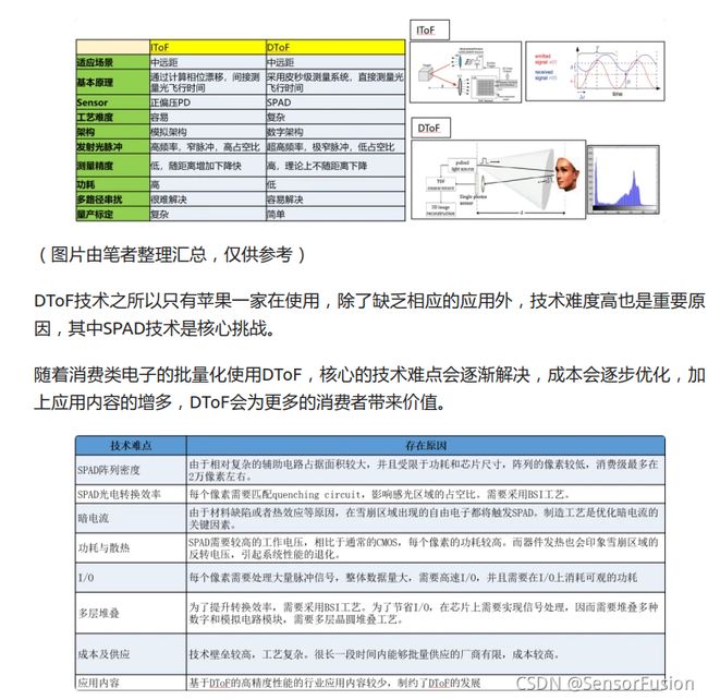
特点对比如下:
![]()
针对近距离,需要高精度测距,那么结构光可以满足
1:Point Process
直通滤波器 体素滤波器 统计滤波器 条件滤波
半径滤波器 双边滤波 高斯滤波
均匀采样滤波 移动最小二乘法光滑滤波
基于权重局部优化投影 (WLOP) 简化算法 DoN算法
以及各种通过规则进行点调整或者删除的都可以成为滤波算法
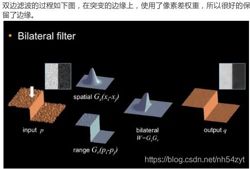
双边滤波,双边滤波主要作用是具有保边的功能,即在滤波的过程中不会连带边界一起都平滑掉,这样有利于计算准确的法线。这里我们主要介绍其实现过程,算法会在后续补充上。
直通滤波器:对于在空间分布有一定空间特征的点云数据,比如使用线结构光扫描的方式采集点云,沿z向分布较广,但x,y向的分布处于有限范围内。此时可使用直通滤波器,确定点云在x或y方向上的范围,可较快剪除离群点,达到第一步粗处理的目的。
体素滤波器:体素的概念类似于像素,使用AABB包围盒将点云数据体素化,一般体素越密集的地方信息越多,噪音点及离群点可通过体素网格去除。另一方面如果使用高分辨率相机等设备对点云进行采集,往往点云会较为密集。过多的点云数量会对后续分割工作带来困难。体素滤波器可以达到向下采样同时不破坏点云本身几何结构的功能。
统计滤波器:考虑到离群点的特征,则可以定义某处点云小于某个密度,既点云无效。计算每个点到其最近的k个点平均距离。则点云中所有点的距离应构成高斯分布。给定均值与方差,可剔除3∑之外的点。
条件滤波:条件滤波器通过设定滤波条件进行滤波,有点分段函数的味道,当点云在一定范围则留下,不在则舍弃。
半径滤波器:半径滤波器与统计滤波器相比更加简单粗暴。以某点为中心画一个圆计算落在该圆中点的数量,当数量大于给定值时,则保留该点,数量小于给定值则剔除该点。此算法运行速度快,依序迭代留下的点一定是最密集的,但是圆的半径和圆内点的数目都需要人工指定。
2:手眼标定
定义:
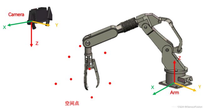
在机器人校准测量、机器人手眼协调以及机器人辅助测量等领域,都要求知道机器人执行器末端(抓取臂)坐标系和传感器(比如用来测量三维空间中目标位置和方向并固定在机器人手上的摄像机)坐标系之间的相互关系,确定这种转换关系在机器人领域就是通常所说的手眼标定。
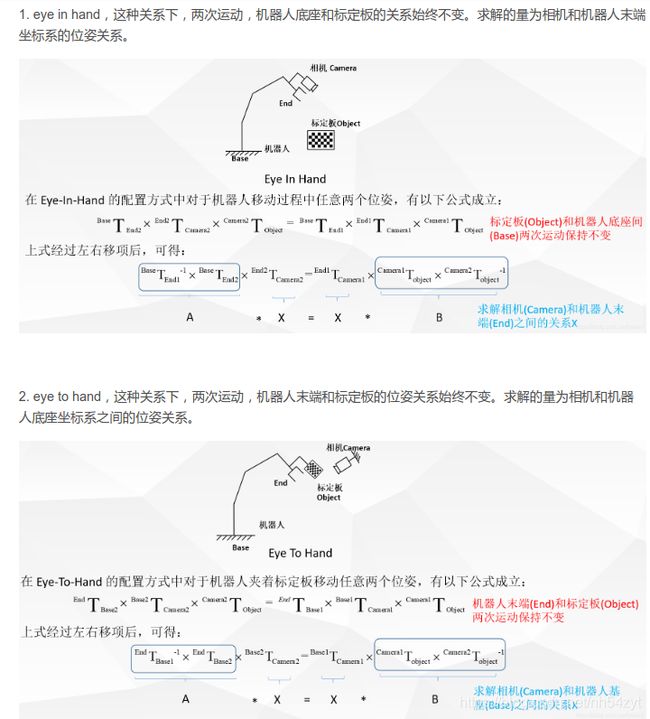
根据摄像机与机器人相互位置的不同,手眼视觉系统分为Eye-in-Hand系统和Eye-to-Hand系统。
Eye-in-Hand系统的摄像机安装在机器人手部末端(end-effector),在机器人工作过程中随机器人一起运动。 Eye-to-Hand系统的摄像机安装在机器人本体外的固定位置,在机器人工作工程中不随机器人一起运动。
Eye-in-Hand系统的在工业机器人中应用比较广泛,随着机械手逐渐接近目标,摄像机与目标的距离越来越小,被测物体位置参数的绝对误差会随之降低。在Eye-in-Hand系统中,采用基于图像的视觉控制、基于位置的视觉控制以及结合两者的混合视觉控制,可以快速有效地标定被测物体的坐标。
![]()
![]()
手眼标定:
针对rgb相机,
先求取内参和畸变参数,通过张正友法标定相机的内参矩阵和畸变参数;标定相机外参矩阵,用于图像坐标与世界坐标的转换;设置N个特征点(N>3N>3),计算其世界坐标,移动机械臂工作末端到特征点,记录末端坐标,获得N组数据; 计算两组数据的RR和tt,其中特征点世界坐标为A组数据,末端坐标为B组数据
求解过程
计算两组数据的变换矩阵实际上为3D-3D的位姿估计问题,可用迭代最近点(Iterative Closest Point, ICP)求解,实现方法有两种:
利用线性代数的求解(主要是 SVD)(建议采用该方法) 利用非线性优化方式的求解(类似于 Bundle Adjustment)
更多ICP相关算法可参考:Calibration and Registration Techniques for Robotics的Registering Two Sets of 3DoF Data 简单来说,2D相机通过张正友标定法,是提取黑白棋盘格的角点,来得到相机位姿变换的。
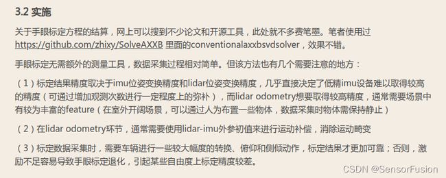
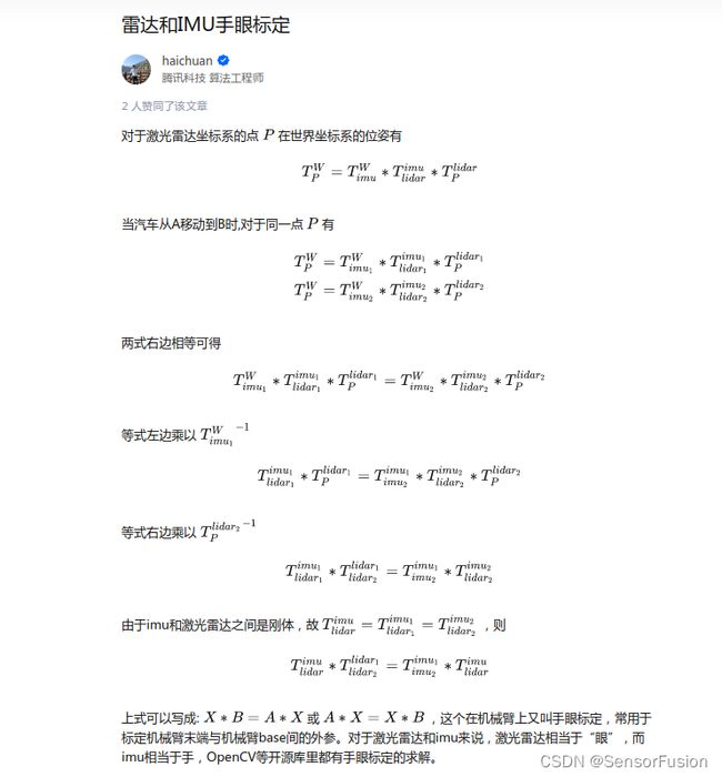
针对lidar-imu
https://zhuanlan.zhihu.com/p/420345691
P是lidar测量的点,这个点在世界坐标系是不变的,利用空间中固定的点,求解imu+lidar
https://www.cnblogs.com/qiushanju/p/11947472.html
针对点云相机,
眼在手
在机械臂上安装好相机(需绝对固定),使用代码或者示教器变换多个位姿,让相机对着一个物体进行拍照。我们通过这几帧点云之间的变换关系,及采集这几帧点云时的机械臂位姿,就能得到手眼矩阵了
https://blog.csdn.net/weixin_42156097/article/details/110957847
点云相机呢,就需要利用它的点云数据了。
原理就是:
在机械臂上安装好相机(需绝对固定),使用代码或者示教器变换多个位姿,让相机对着一个物体进行拍照。我们通过这几帧点云之间的变换关系,及采集这几帧点云时的机械臂位姿,就能得到手眼矩阵了
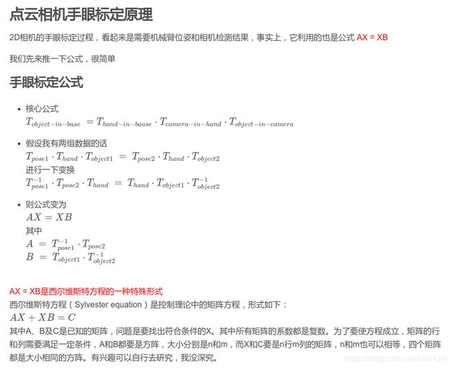
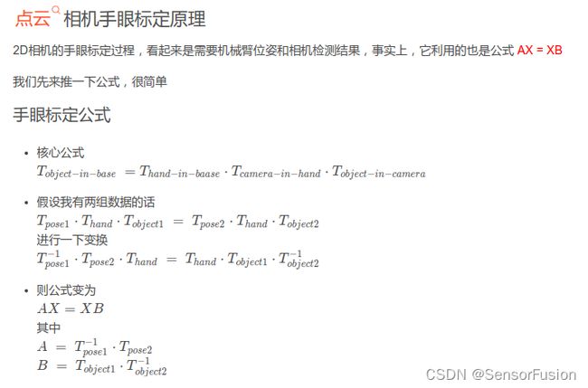
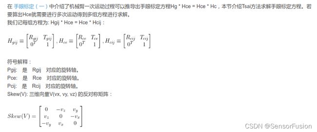
为啥使用AX=XB
使用点云相机在估计物体的位姿,实际上是一个高精度的算法工作,而进行手眼标定过程往往是机械臂项目的开始。我们不希望,连手眼标定矩阵都没搞好,就去准确的估计物体位姿了。
我们可以说,使用AX = XB的方法,能在手眼标定过程中,暂时不去优化待检测物体的位姿估计,能够快速的完成机械臂的环境搭建工作

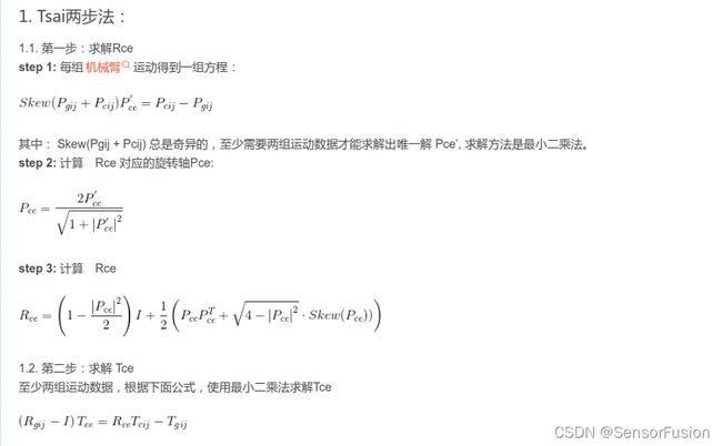
求解出A和B以后,如何求解X,
有多种方法,至少需要3组数据进行求解
opencv方法:
calibratehandEye()
主要用来计算AX=BX ,函数输入就是两组RT及求解方法,输出就是解
例如: opencv 4.1.0以上版本有手眼标定的求解方法;
标定的时候,如果是rgb是相机,则标定板固件不动。一般已棋盘格左上角为顶点,真实的格子大小是知道的,z为0。
例如可以利用RSAI算法求解X
https://blog.csdn.net/Sandy_WYM_/article/details/83996479
clc;
clear;
num = 14;
A=zeros(4,4,num);
B=zeros(4,4,num);
A(:,:,1)=[0.9997980101273221, -0.01607111192618671, -0.01206935570872313, -0.003056556362190066;
 0.01674895934272706, 0.9981564074674805, 0.05833747642946587, 0.04142996722424749;
 0.01110954509912888, -0.0585278414516273, 0.9982239653950075, 0.009770159468120519;
 0, 0, 0, 1];
B(:,:,1)=[1, -0.011, -0.007, 0.001496;
 0.011, 0.998, 0.055, -0.042174;
 0.006, -0.055, 0.998, -0.012222;
 0, 0, 0, 1];
A(:,:,2)=[0.9980680730327043, 0.0007536742026831328, 0.06212542640675847, 0.01423670063468297;
 -0.006760465497263591, 0.9953066584308737, 0.09653467238220965, 0.01882418647028945;
 -0.06176110098209641, -0.09676817546987918, 0.9933888980914715, 0.01173102823510962;
 0, 0, 0, 1];
B(:,:,2)=[0.998, 0.004, 0.06900000000000001, -0.012265;
 -0.01, 0.996, 0.09, -0.011046;
 -0.068, -0.091, 0.994, 0.003755;
 0, 0, 0, 1];

A(:,:,14) = [-0.4414521651027964, 0.8817551781832361, 0.1662161482121915, 0.3023485424774342;
 -0.882839153220496, -0.4599336869135009, 0.09516315351470551, 0.2369591083970457;
 0.1603590169968309, -0.1047321446927015, 0.9814867161376279, -0.03719682838587067;
 0, 0, 0, 1];
B(:,:,14) = [-0.4513495456200001, 0.8834837791600001, 0.126, 0.009211;
 -0.8814102394400001, -0.46382754358, 0.089, -0.039305;
 0.13653720861, -0.07123616128, 0.988, -0.000394;
 0, 0, 0, 1];

X= tsai(A,B)
function Sk = skew( x )

   Sk = [0,-x(3),x(2);x(3),0,-x(1);-x(2),x(1),0];

end
function X = tsai(A,B)
% Calculates the least squares solution of
% AX = XB
%
% A New Technique for Fully Autonomous
% and Efficient 3D Robotics Hand/Eye Calibration
% Lenz Tsai
% Mili Shah
% July 2014

[m,n] = size(A); n = n/4;
S = zeros(3*n,3);
v = zeros(3*n,1);

%Calculate best rotation R
for i = 1:n
    A1 = logm(A(1:3,4*i-3:4*i-1));
    B1 = logm(B(1:3,4*i-3:4*i-1));
    a = [A1(3,2) A1(1,3) A1(2,1)]'; a = a/norm(a);
    b = [B1(3,2) B1(1,3) B1(2,1)]'; b = b/norm(b);
    S(3*i-2:3*i,:) = skew(a+b);
    v(3*i-2:3*i,:) = a-b;
end
x = S\v;
theta = 2*atan(norm(x));
x = x/norm(x);
R = (eye(3)*cos(theta) + sin(theta)*skew(x) + (1-cos(theta))*x*x')';

%Calculate best translation t
C = zeros(3*n,3);
d = zeros(3*n,1);
I = eye(3);

for i = 1:n
    C(3*i-2:3*i,:) = I - A(1:3,4*i-3:4*i-1);
    d(3*i-2:3*i,:) = A(1:3,4*i)-R*B(1:3,4*i);
end

t = C\d;

%Put everything together to form X
X = [R t;0 0 0 1];
眼在手外
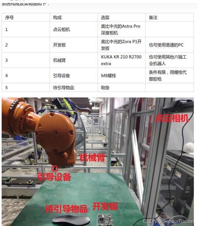
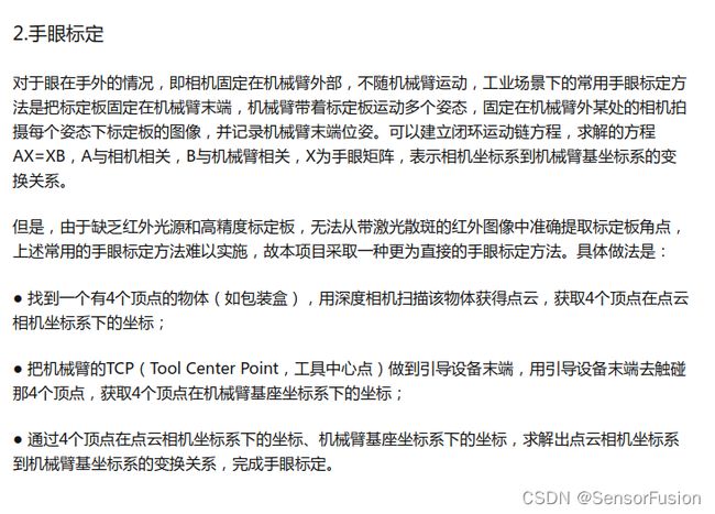
https://zhuanlan.zhihu.com/p/346980675
3:三维点云算法,平面,线段,关键点求解
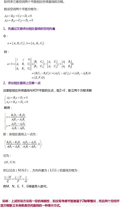
两平面的相交直线
①: 点法式求解
如:
两平面交线方程
求平面x-2y+z=2和2x+y-z=4的交线的标准方程
解:
交线垂直两平面的法矢量,{1,-2,1}、{2,1,-1},两法矢量叉积得交线的方向矢量为{1,3,5}再另z=0,解得x=2,y=0即直线过(2,0,0),所以标准方程为(x-2)/1=y/3=z/5
② 平面联立求解:
关键是计算出来的交线如何用
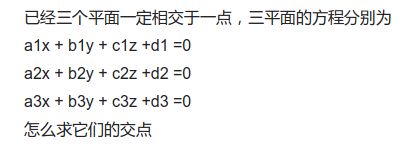
对于两个空间平面
a1x+b1y+c1z+d1=0
a2x+b2y+c2z+d2=0
联立他们就是交线的一种表达式了
交线的方向,可以用两个平面的法向量叉乘得到
交线上的任意一点,可以通过联立的两个方程式做个减法,得到公式:
(a1-a2)x + (b1-b2)y + (c1-c2)z + (d1-d2) = 0
随意选择一组可以满足等式条件的x,y,z数值就可以了
。。。。。。。。。。。。。。。。。。。。。。。。。。。。。。。。。。。。。。。。。。。。。。。。。。。。。。。。。。。。。。。。。。。。。。。。。。。。。。。。。。。。。。。。。。。。。。。。。。。。。。。。。。。。。。。。。。。。。
点云分割:
直接利用法向量加聚类算法
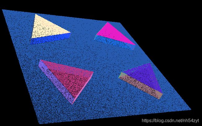
平面检测:
https://www.cnblogs.com/wishchin/p/9200319.html
三维点云平面拟合方法:
一: 拟合一个平面:使用SVD分解,QR分解:
根据协方差矩阵的SVD变换,最小奇异值对应的奇异向量就是平面的方向。
二:利用Ransac算法进行拟合
通过迭代方式估计数学模型的参数
直接利用PCA等主方向求解思路
4:Pcl::PointCloud和pcl::PointCloud::Ptr类型的转换
1.PointCloud::Ptr—>PointCloud
pcl::PointCloudpcl::PointXYZ cloud;
pcl::PointCloudpcl::PointXYZ::Ptr cloud_ptr(new pcl::PointCloudpcl::PointXYZ);
cloud=*cloud_ptr;
2.PointCloud—>PointCloud::Ptr
pcl::PointCloudpcl::PointXYZ::Ptr cloud_ptr(new pcl::PointCloudpcl::PointXYZ);
pcl::PointCloudpcl::PointXYZ cloud;
cloud_ptr=cloud.makeShared();
1.
pcl::PointCloud<pcl::PointXYZ> cloudA;
pcl::octree::OctreePointCloudSearch<pcl::PointXYZ> octree(resolution);
octree.setInputCloud(cloudA.makeShared());

2.
pcl::PointCloud<pcl::PointXYZ>::Ptr cloudA(new pcl::PointCloud<pcl::PointXYZ>);
pcl::octree::OctreePointCloudSearch<pcl::PointXYZ> octree(resolution);
octree.setInputCloud(cloudA);
5:对比二维三维区域生长算法
二维原理:
(1)原理:
区域生长是根据预先定义的生长准则将像素或子区域组合为更大区域的过程。
基本方法是从一组“种子”点开始(原点),
将与种子相似的临近像素(在特定范围内的灰度或颜色)添加到种子栈中,
不断迭代,生成一大片区域。严谨的数学定义可以查看冈萨雷斯的数字图像处理。
(2)算法实现
算法的步骤如下:
创建一个与原图像大小相同的空白图像
将种子点存入vector中,vector中存储待生长的种子点
依次弹出种子点并判断种子点如周围8领域的关系(生长规则)
并与最大与最小阈值进行比较,符合条件则作为下次生长的种子点
vector中不存在种子点后就停止生长
(3)与三维区域生长算法不同的地方:
不需要kd-tree搜索邻域,2D图片的区域生长算法生长方向为八个且方向固定
三维区域生长,是否为同一类看法线阈值,是否可以作为种子点看曲率阈值。
而2D图片的区域生长这两个阈值为同一个灰度阈值。
/***************************************************************************************
Function: 区域生长算法
Input: src 待处理原图像 pt 初始生长点 th 生长的阈值条件
Output: 肺实质的所在的区域 实质区是白色,其他区域是黑色
Description: 生长结果区域标记为白色(255),背景色为黑色(0)
Return: Mat
***************************************************************************************/
#include ![]()
三维原理:
算法理论:
区域生长分割算法广泛应用于图像分割中,二维图像常常采取区域生长分割算法实现图像分割,由于其分割的高效性,现已被应用于3D分割中,PCL中的类pcl::RegionGrowing用来实现点云的区域生长分割。区域生长分割是基于点云法线的分割算法,算法的主要思路如下:
(1)根据点的曲率值对点云进行排序,曲率最小的点叫做初始种子点,区域生长算法从曲率最小的种子点开始生长,初始种子点所在区域为最平滑区域,从初始种子点所在的区域开始生长可减小分割片段的总数,从而提高算法的效率。
(2)设置一空的聚类区域C和空的种子点序列Q,选好初始种子点,将其加入种子点序列,并搜索该种子点的领域点,计算每一个领域点法线与种子点法线之间的夹角,小于设定的平滑阀值时,将领域点加入到C中,同时判断该领域点的曲率值是否小于曲率阀值,将小于曲率阔值的领域点加入种子点序列Q中,在Q中重新选择新的种子点重复上述步骤,直到Q中序列为空,算法结束
(1)首先计算出来各点的曲率值,将曲率值按照从小到大的顺序进行排序。

(2)设置一空的种子点序列和一个空的聚类数组。

(3)选取曲率最小的点放入上述种子点序列中。

(4)从序列中拿出来一个种子点搜索其邻域。

(5)搜索到邻域后,这些点先过法线夹角阈值,通过的保留到聚类数据,
然后再从这些通过法线夹角阈值的点中,检查是否通过曲率阈值,
通过的加入种子点序列。即比较邻域点的法线与当前种子点法线之间的夹角,如
果小于阈值将该邻域点加入聚类数组。再从这些小于法线阈值的点中判断是否小于曲率阈值,
如果小于则将该邻域点加入种子序列。

(6)结束后删除用过的种子点,用下一个种子点重复第(4)(5)步,直至种子点序列清空为止。

(7)从曲率排序的点中,即从小到大的排序,取聚类数组中没有的点作为种子点,重复第(2)(3)(4)(5)(6)步骤。

可以理解为,聚类出的同一个平面上的点,曲率小于某一阈值(设置的曲率阈值),才可以当作种子点,继续生长。


曲率阈值和法相量夹角阈值都是需要提前设置的。首先将曲率从小到大排序,
选取最小的加入种子序列,这时候种子序列里只有一个点,
然后拿出种子序列中的一个点(这时候也就是这个刚放进去的唯一的点),
和设置了指定范围的临域中的点比较法相量夹角,如果小于法相量夹角阈值,
则这个临域的点和种子点是同一个平面,另外,如果这个点的曲率小于曲率阈值,
则把这个点当作种子点,放入种子序列。反复上面的过程,直到种子序列为空,
此时长出了一个平面。

其实在实际源代码中你会看到有一个做标记的过程还有一个记录聚类个数的过程。
(分割其实就是赋标签的过程,种子点开始生长,满足条件就一直长,
直到不满足条件了就不长了,把这些点标记一个标签,再从剩下的点里面重新选种子点,
再次生长,标签累加,一直迭代到没有点为止。)
(-1代表还没有标记的点云 如果!=-1说明该点已经标记过标签了
已经分割过的点云不参与后续的分割。)
曲率计算
区域生长,种子点选择
点云曲率大的点集,表示edge。
点云曲率小的点集,表示plannar。
6:法线应用
边界求解思路:
基于法线完成的边界估计主要是利用各个法线方向之间的夹角来做的判断(所以有个设置角度的阈值参数)。(根据法线夹角确定哪些点是边界点)
pcl应用:
对于边界的估计就是这个函数boundEst.setRadiusSearch(re),参数re也设置为分辨率(此处的分辨率指的是点云的密度)的10倍,太小则内部的很多点就都当成边界点了。最后一个参数是边界判断时的角度阈值,默认值为PI/2,此处设置为PI/4,用户也可以根据需要进行更改。
法线预测加速:
PCL提供了表面法线估计的加速实现,基于OpenMP使用多核/多线程来加速计算。 该类的名称是pcl :: NormalEstimationOMP,其API与单线程pcl :: NormalEstimation 100%兼容。 在具有8个内核的系统上,一般计算时间可以加快6-8倍。
include <pcl/point_types.h>
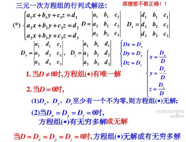
#include 7:三个平面的交点(有解,无解)三元一次方程
三个平面,三条交线,获取的点:
        float a1 = plane_list[plane_index1].normal[0];
        float b1 = plane_list[plane_index1].normal[1];
        float c1 = plane_list[plane_index1].normal[2];
        float x1 = plane_list[plane_index1].p_center.x;
        float y1 = plane_list[plane_index1].p_center.y;
        float z1 = plane_list[plane_index1].p_center.z;
        float a2 = plane_list[plane_index2].normal[0];
        float b2 = plane_list[plane_index2].normal[1];
        float c2 = plane_list[plane_index2].normal[2];
        float x2 = plane_list[plane_index2].p_center.x;
        float y2 = plane_list[plane_index2].p_center.y;
        float z2 = plane_list[plane_index2].p_center.z;
        float theta = a1 * a2 + b1 * b2 + c1 * c2;
        //
        float point_dis_threshold = 0.00;
        if (theta > theta_max_ && theta < theta_min_)
        {
          // for (int i = 0; i < 6; i++) {
          if (plane_list[plane_index1].cloud.size() > 0 ||
              plane_list[plane_index2].cloud.size() > 0)
          {
            float matrix[4][5];
            matrix[1][1] = a1;
            matrix[1][2] = b1;
            matrix[1][3] = c1;
            matrix[1][4] = a1 * x1 + b1 * y1 + c1 * z1;
            matrix[2][1] = a2;
            matrix[2][2] = b2;
            matrix[2][3] = c2;
            matrix[2][4] = a2 * x2 + b2 * y2 + c2 * z2;
            // six types
            std::vector<Eigen::Vector3d> points;
            Eigen::Vector3d point;
            matrix[3][1] = 1;
            matrix[3][2] = 0;
            matrix[3][3] = 0;
            matrix[3][4] = origin[0];
            calc<float>(matrix, point);  // 判断和 体素 100 xoy面交点
            if (point[0] >= origin[0] - point_dis_threshold &&
                point[0] <= origin[0] + voxel_size + point_dis_threshold &&
                point[1] >= origin[1] - point_dis_threshold &&
                point[1] <= origin[1] + voxel_size + point_dis_threshold &&
                point[2] >= origin[2] - point_dis_threshold &&
                point[2] <= origin[2] + voxel_size + point_dis_threshold)
            {
              points.push_back(point);
            }
template void calc(T matrix[4][5], Eigen::Vector3d &solution)
// 判断体素内两个平面是否和体素边框相交
// 如果相交,求解的相交交点内的直线特征点
template <class T> void calc(T matrix[4][5], Eigen::Vector3d &solution) {
  T base_D = matrix[1][1] * matrix[2][2] * matrix[3][3] +
             matrix[2][1] * matrix[3][2] * matrix[1][3] +
             matrix[3][1] * matrix[1][2] * matrix[2][3]; //计算行列式
  base_D = base_D - (matrix[1][3] * matrix[2][2] * matrix[3][1] +
                     matrix[1][1] * matrix[2][3] * matrix[3][2] +
                     matrix[1][2] * matrix[2][1] * matrix[3][3]);

  if (base_D != 0) {
    T x_D = matrix[1][4] * matrix[2][2] * matrix[3][3] +
            matrix[2][4] * matrix[3][2] * matrix[1][3] +
            matrix[3][4] * matrix[1][2] * matrix[2][3];
    x_D = x_D - (matrix[1][3] * matrix[2][2] * matrix[3][4] +
                 matrix[1][4] * matrix[2][3] * matrix[3][2] +
                 matrix[1][2] * matrix[2][4] * matrix[3][3]);
    T y_D = matrix[1][1] * matrix[2][4] * matrix[3][3] +
            matrix[2][1] * matrix[3][4] * matrix[1][3] +
            matrix[3][1] * matrix[1][4] * matrix[2][3];
    y_D = y_D - (matrix[1][3] * matrix[2][4] * matrix[3][1] +
                 matrix[1][1] * matrix[2][3] * matrix[3][4] +
                 matrix[1][4] * matrix[2][1] * matrix[3][3]);
    T z_D = matrix[1][1] * matrix[2][2] * matrix[3][4] +
            matrix[2][1] * matrix[3][2] * matrix[1][4] +
            matrix[3][1] * matrix[1][2] * matrix[2][4];
    z_D = z_D - (matrix[1][4] * matrix[2][2] * matrix[3][1] +
                 matrix[1][1] * matrix[2][4] * matrix[3][2] +
                 matrix[1][2] * matrix[2][1] * matrix[3][4]);

    T x = x_D / base_D;
    T y = y_D / base_D;
    T z = z_D / base_D;
    // cout << "[ x:" << x << "; y:" << y << "; z:" << z << " ]" << endl;
    solution[0] = x;
    solution[1] = y;
    solution[2] = z;
  } else {
    cout << "【无解】";
    solution[0] = 0;
    solution[1] = 0;
    solution[2] = 0;
    //        return DBL_MIN;
  }
求解:
8:点云上采样,点云重建
目的:
实现了点云的良好重建,在密度、完整性和均匀性
深度学习的上采样方法:
https://cloud.tencent.com/developer/article/1556655
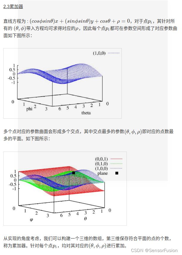
#include 9:平面求解多种方式 Ransac、 3D hough
ransac:
bool RansacPlaneModel(
    const pcl::PointCloud<pcl::PointXYZI>::Ptr cloud,
    Eigen::Vector4f &normals) {
  if (cloud->points.size() < 5) {
    error_str = "too less points!!!";
    calibration_error(error_str.c_str());
    return false;
  }
  if (0) {
    Eigen::VectorXf plane_model_coefficients_;
    pcl::SampleConsensusModelPlane<pcl::PointXYZI>::Ptr model_p(
        new pcl::SampleConsensusModelPlane<pcl::PointXYZI>(cloud));
    pcl::RandomSampleConsensus<pcl::PointXYZI> ransac(model_p);
    ransac.setDistanceThreshold(0.05);
    ransac.computeModel();
    ransac.getModelCoefficients(plane_model_coefficients_);
    if (plane_model_coefficients_(2) < 0.) {
      plane_model_coefficients_(0) *= -1;
      plane_model_coefficients_(1) *= -1;
      plane_model_coefficients_(2) *= -1;
      plane_model_coefficients_(3) *= -1;
    }
    normals = plane_model_coefficients_.block(0, 0, 4, 1);
    return true;
  } else {
    pcl::SACSegmentation<PointType> seg;
    pcl::PointIndices::Ptr inliers(new pcl::PointIndices);
    pcl::ModelCoefficients::Ptr coefficients(new pcl::ModelCoefficients);
    seg.setOptimizeCoefficients(true);
    seg.setModelType(pcl::SACMODEL_PLANE);
    seg.setMethodType(pcl::SAC_RANSAC);
    seg.setMaxIterations(300);
    seg.setDistanceThreshold(0.06);
    seg.setInputCloud(cloud);
    seg.segment(*inliers, *coefficients);
    if (inliers->indices.size() == 0) {
      info_str = "Could not estimate a planar model for the given dataset.";
      calibration_info(info_str.c_str());
      return false;
    }
    normals = {coefficients->values[0], coefficients->values[1],
               coefficients->values[2], coefficients->values[3]};
    return true;
  }
}
3D hough
#define  PI 3.141592653
void HoughTransform(const std::vector<Point>& input, double& A, double& B, double& C, double& D)
{
	int n = input.size();
	if (n < 3)
		return;

	double theta_start=0, theta_end=PI;
	double phi_start=0, phi_end=PI;
	//double phi_start = 0.25*PI, phi_end = 0.75*PI;
	double anglestep=PI/90, disstep=0.1;

	boundingbox box;
	calcboundbox(input, box);
	double d_start = -box.diag() / 2.0, d_end = box.diag() / 2.0;

	int thetas = ceil((theta_end - theta_start) / anglestep);
	int phis = ceil((phi_end - phi_start) / anglestep);
	int dises = ceil( box.diag()/disstep);

	int*** cube = new int**[thetas];
	for (int i = 0; i < thetas;++i)
	{
		cube[i] = new int*[phis];
		for (int j = 0; j < phis; ++j)
		{
			cube[i][j] = new int[dises];
			memset(cube[i][j], 0, sizeof(int)*dises);
		}
	}

	//cos(theta)sin(phi)X+sin(theta)sin(phi)Y+cos(phi)Z = D
	Point ptCenter = box.center();
	for (int i = 0; i < n;++i)
	{
		const Point& ptOrigin = input[i];
		Point point = ptOrigin - ptCenter;

		double theta = theta_start;
		for(int j = 0; j < thetas; ++j)
		{
			int** row = cube[j];
			double phi = phi_start;
			for (int k = 0; k < phis; ++k)
			{
				int* col = row[k];

				double sinphi = sin(phi);
				double d = cos(theta)*sinphi*point.x + sin(theta)*sinphi*point.y + cos(phi)*point.z;

				int d_index = floor((d - d_start) / disstep);
				++(col[d_index]);

				phi += anglestep;
				if (phi > phi_end)
					break;
			}
			theta += anglestep;
			if (theta > theta_end)
				break;
		}
	}//all points

	int buf = 1;
	int maxcount = 0;
	int xmax, ymax, zmax;

	for (int i = 0; i < thetas;++i)
		for (int j = 0; j < phis; ++j)
				for (int k = buf; k < dises - buf;++k)
			{
				int count = 0;
				for (int x = i - buf; x <= i + buf; ++x)
					for (int y = j - buf; y <= j + buf; ++y)
						for (int z = k - buf; z <= k + buf; ++z)
						{
							count += cube[x<0?x+thetas:x%thetas][y<0?y+phis:y%phis][z];
						}

				if (count > maxcount)
				{
					xmax = i;
					ymax = j;
					zmax = k;
					maxcount = count;
				}
			}

	double theta = theta_start + xmax*anglestep;
	double phi = phi_start + ymax*anglestep;
	double d = d_start + zmax*disstep;

	A = cos(theta)*sin(phi);
	B = sin(theta)*sin(phi);
	C = cos(phi);
	D = -d - (A*ptCenter.x + B*ptCenter.y+C*ptCenter.z);
	//std::cout << A << " , " << B << " , " << C << " , "<< D << std::endl;
	//释放cube
	for (int i = 0; i < thetas; ++i)
	{
		int** row = cube[i];
		for (int j = 0; j < phis;++j)
		{
			int* col = row[j];
			delete[] col;
		}
		delete[] row;
	}
	delete[] cube;
}
Point、boundingbox
class Point
{
public:
	double x, y, z;
	Point(double ix,double iy,double iz) :
		x(ix), y(iy), z(iz){}

	Point operator-(const Point& pt) const
	{
		return Point(x - pt.x, y - pt.y, z - pt.z);
	}
};
typedef Point Vector;

class boundingbox
{
public:
	double x_min, x_max;
	double y_min, y_max;
	double z_min, z_max;

public:
	double diag() const
	{
		double dx = x_max - x_min;
		double dy = y_max - y_min;
		double dz = z_max - z_min;

		return sqrt(dx*dx + dy*dy + dz*dz);
	}

	boundingbox():
		x_min(std::numeric_limits<double>::max()),
		y_min(std::numeric_limits<double>::max()),
		z_min(std::numeric_limits<double>::max()),
		x_max(-std::numeric_limits<double>::max()),
		y_max(-std::numeric_limits<double>::max()),
		z_max(-std::numeric_limits<double>::max())
	{}

	Point center() const
	{
		return Point((x_max + x_min) / 2.0,(y_min+y_max) / 2.0, (z_min+z_max) / 2.0);
	}
};

void calcboundbox(const std::vector<Point>& input, boundingbox& box)
{
	for (int i = 0, n = input.size(); i < n;++i)
	{
		auto point = input[i];
		if (point.x < box.x_min)
			box.x_min = point.x;
		if (point.y < box.y_min)
			box.y_min = point.y;
		if (point.z < box.z_min)
			box.z_min = point.z;
		if (point.x > box.x_max)
			box.x_max = point.x;
		if (point.y > box.y_max)
			box.y_max = point.y;
		if (point.z > box.z_max)
			box.z_max = point.z;
	}
}
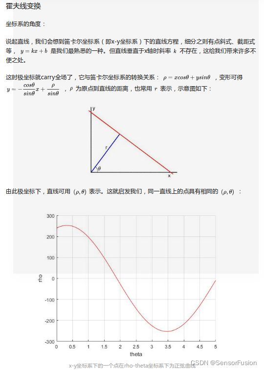
二维原理:
同一直线上的点具有相同的:距离+角度
原理:经过某一点的直线在参数空间中可以由一条正弦曲线来表示。
即过一点的直线非常多
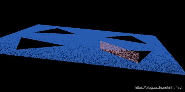
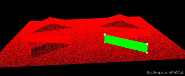
10:三角网格化及三角剖分
三角剖分是代数拓扑学里最基本的研究方法。 以曲面为例, 我们把曲面剖开成一块块碎片,要求满足下面条件: (1)每块碎片都是曲边三角形; (2)曲面上任何两个这样的曲边三角形,要么不相交,要么恰好相交于一条公共边(不能同时交两条或两条以上的边)。
定义】三角剖分:假设V是二维实数域上的有限点集,边e是由点集中的点作为端点构成的封闭线段, E为e的集合。那么该点集V的一个三角剖分T=(V,E)是一个平面图G,该平面图满足条件:
1.除了端点,平面图中的边不包含点集中的任何点。
2.没有相交边。
3.平面图中所有的面都是三角面,且所有三角面的合集是散点集V的凸包。
在实际中运用的最多的三角剖分是Delaunay三角剖分,它是一种特殊的三角剖分。先从Delaunay边说起:
【定义】Delaunay边:假设E中的一条边e(两个端点为a,b),e若满足下列条件,则称之为Delaunay边:存在一个圆经过a,b两点,圆内(注意是圆内,圆上最多三点共圆)不含点集V中任何其他的点,这一特性又称空圆特性。
【定义】Delaunay三角剖分:如果点集V的一个三角剖分T只包含Delaunay边,那么该三角剖分称为Delaunay三角剖分。
【定义】假设T为V的任一三角剖分,则T是V的一个Delaunay三角剖分,当前仅当T中的每个三角形的外接圆的内部不包含V中任何的点。
关于Delaunay三角形的算法,有翻边算法、逐点插入算法、分割合并算法、Bowyer-Watson算法等。
而在这几种算法中,逐点插入算法比较简单、易懂,在本文中只针对该算法进行讨论,该算法也是目前使用最为广泛的Delaunay算法。
在该算法中,主要应用Delaunay三角形,理解下来就是 每一个三角形的外接圆圆内不能存在点集内的其它任何一点,而有时候会出现点在外接圆上的情况,这种情况被称为“退化”。
三角剖分的解析:
https://blog.csdn.net/axelboss/article/details/101070789
https://www.cnblogs.com/RenLiQQ/archive/2008/02/06/1065399.html
三角网格化的应用
体积求解:
论文
EFFICIENT FEATURE EXTRACTION FOR 2D/3D OBJECTS
IN MESH REPRESENTATION
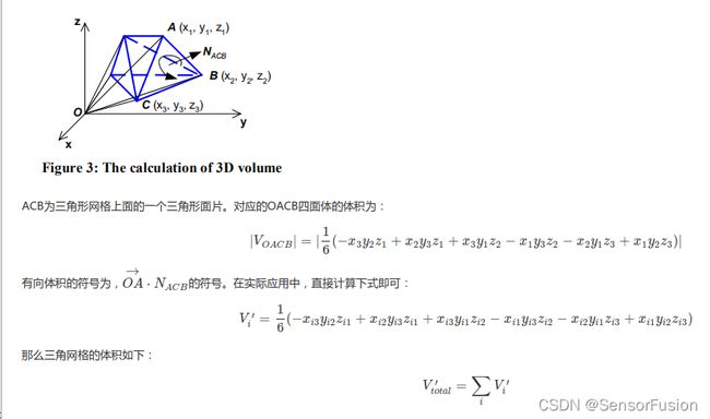
#include 借助VTK
#include " << std::endl;
std::cerr <<"Supported File Extensions: .ply, .vtp, .obj, .stl, .vtk, .g";
std::cerr << std::endl;
return EXIT_FAILURE;
}
// Method of accessing polyData
vtkSmartPointer<vtkPolyData> polyData = ReadPolyData(argc > 1 ? argv[1] : "");;
//vtkMassProperties requires a closed mesh and triangles with consistent ordering, this must be done to the data before finding volumes
vtkSmartPointer<vtkFillHolesFilter> fillHolesFilter =
vtkSmartPointer<vtkFillHolesFilter>::New();
fillHolesFilter->SetInputData(polyData);
fillHolesFilter->SetHoleSize(100.0);
vtkSmartPointer<vtkTriangleFilter> triangleFilter =
vtkSmartPointer<vtkTriangleFilter>::New();
triangleFilter->SetInputConnection(fillHolesFilter->GetOutputPort());
vtkSmartPointer<vtkPolyDataNormals> normals = vtkSmartPointer<vtkPolyDataNormals>::New();
normals->SetInputConnection(triangleFilter->GetOutputPort());
normals->ConsistencyOn();
normals->SplittingOff();
//Access MassProperties to to get volumes
vtkSmartPointer<vtkMassProperties> massProperties = vtkSmartPointer<vtkMassProperties>::New();
massProperties->SetInputConnection(normals->GetOutputPort());
massProperties->Update();
std::cout << "Volume: " << massProperties->GetVolume() << std::endl
<< " VolumeX: " << massProperties->GetVolumeX() << std::endl
<< " VolumeY: " << massProperties->GetVolumeY() << std::endl
<< " VolumeZ: " << massProperties->GetVolumeZ() << std::endl;
return EXIT_SUCCESS;
}
namespace
{
vtkSmartPointer<vtkPolyData> ReadPolyData(const char *fileName)
{
// where data will be stored and returned
vtkSmartPointer<vtkPolyData> polyData;
// find extension of file
std::string extension = vtksys::SystemTools::GetFilenameExtension(std::string(fileName));
// find filetype so vtk can read properly
if (extension == ".ply")
{
vtkSmartPointer<vtkPLYReader> reader =
vtkSmartPointer<vtkPLYReader>::New();
reader->SetFileName (fileName);
reader->Update();
polyData = reader->GetOutput();
}
else
{
// If the user has not used a valid file type, explain
std::cerr << "Invalid file Type" << std::endl;
std::cerr <<"Supported File Extensions: .ply, .vtp, .obj, .stl, .vtk, .g" << std::endl;
exit(0);
}
return polyData;
}
}
PCL网格化
#include with an appropriate type
pcl::PointCloud<pcl::PointXYZ>::Ptr cloud (new pcl::PointCloud<pcl::PointXYZ>);
pcl::PCLPointCloud2 cloud_blob;
pcl::io::loadPCDFile ("..\\..\\source\\table_scene_lms400_downsampled.pcd", cloud_blob);
pcl::fromPCLPointCloud2(cloud_blob, *cloud);
//* the data should be available in cloud
// Normal estimation*
pcl::NormalEstimation<pcl::PointXYZ, pcl::Normal> n;//设置法线估计对象
pcl::PointCloud<pcl::Normal>::Ptr normals (new pcl::PointCloud<pcl::Normal>);//存储估计的法线
pcl::search::KdTree<pcl::PointXYZ>::Ptr tree (new pcl::search::KdTree<pcl::PointXYZ>);//定义kd树指针
tree->setInputCloud (cloud);//用cloud构造tree对象
n.setInputCloud (cloud);//为法线估计对象设置输入点云
n.setSearchMethod (tree);//设置搜索方法
n.setKSearch (20);//设置k邻域搜素的搜索范围
n.compute (*normals);//估计法线
//* normals should not contain the point normals + surface curvatures
// Concatenate the XYZ and normal fields*
pcl::PointCloud<pcl::PointNormal>::Ptr cloud_with_normals (new pcl::PointCloud<pcl::PointNormal>);//
pcl::concatenateFields (*cloud, *normals, *cloud_with_normals);//连接字段,cloud_with_normals存储有向点云
//* cloud_with_normals = cloud + normals
// Create search tree*
pcl::search::KdTree<pcl::PointNormal>::Ptr tree2 (new pcl::search::KdTree<pcl::PointNormal>);//定义搜索树对象
tree2->setInputCloud (cloud_with_normals);//利用有向点云构造tree
// Initialize objects
pcl::GreedyProjectionTriangulation<pcl::PointNormal> gp3;//定义三角化对象
pcl::PolygonMesh triangles;//存储最终三角化的网络模型
// Set the maximum distance between connected points (maximum edge length)
gp3.setSearchRadius (0.025); //设置搜索半径radius,来确定三角化时k一邻近的球半径。
// Set typical values for the parameters
gp3.setMu (2.5); //设置样本点到最近邻域距离的乘积系数 mu 来获得每个样本点的最大搜索距离,这样使得算法自适应点云密度的变化
gp3.setMaximumNearestNeighbors (100);//设置样本点最多可以搜索的邻域数目100 。
gp3.setMaximumSurfaceAngle(M_PI/4); //45 degrees,设置连接时的最大角度 eps_angle ,当某点法线相对于采样点的法线偏离角度超过该最大角度时,连接时就不考虑该点。
gp3.setMinimumAngle(M_PI/18); //10 degrees,设置三角化后三角形的最小角,参数 minimum_angle 为最小角的值。
gp3.setMaximumAngle(2*M_PI/3); //120 degrees,设置三角化后三角形的最大角,参数 maximum_angle 为最大角的值。
gp3.setNormalConsistency(false); //设置一个标志 consistent ,来保证法线朝向一致,如果设置为 true 则会使得算法保持法线方向一致,如果为 false 算法则不会进行法线一致性检查。
// Get result
gp3.setInputCloud (cloud_with_normals);//设置输入点云为有向点云
gp3.setSearchMethod (tree2); //设置搜索方式tree2
gp3.reconstruct (triangles); //重建提取三角化
// std::cout << triangles;
// Additional vertex information
std::vector<int> parts = gp3.getPartIDs();//获得重建后每点的 ID, Parts 从 0 开始编号, a-1 表示未连接的点。
/*
获得重建后每点的状态,取值为 FREE 、 FRINGE 、 BOUNDARY 、 COMPLETED 、 NONE 常量,
其中 NONE 表示未定义,
FREE 表示该点没有在 三 角化后的拓扑内,为自由点,
COMPLETED 表示该点在三角化后的拓扑内,并且邻域都有拓扑点,
BOUNDARY 表示该点在三角化后的拓扑边缘,
FRINGE 表示该点在 三 角化后的拓扑内,其连接会产生重叠边。
*/
std::vector<int> states = gp3.getPointStates();
boost::shared_ptr<pcl::visualization::PCLVisualizer> viewer (new pcl::visualization::PCLVisualizer ("3D Viewer"));
viewer->setBackgroundColor (0, 0, 0);
viewer->addPolygonMesh(triangles,"my");
viewer->addCoordinateSystem (1.0);
viewer->initCameraParameters ();
// 主循环
while (!viewer->wasStopped ())
{
viewer->spinOnce (100);
boost::this_thread::sleep (boost::posix_time::microseconds (100000));
}
// Finish
return (0);
}
11:结构光和TOF深度图
1.深度图像也叫距离影像,是指将从图像采集器到场景中各点的距离(深度)值作为像素值的图像。获取方法有:激光雷达深度成像法、计算机立体视觉成像、坐标测量机法、莫尔条纹法、结构光法。
2.点云:当一束激光照射到物体表面时,所反射的激光会携带方位、距离等信息。若将激光束按照某种轨迹进行扫描,便会边扫描边记录到反射的激光点信息,由于扫描极为精细,则能够得到大量的激光点,因而就可形成激光点云。点云格式有*.las ;*.pcd; *.txt等。
深度图像经过坐标转换可以计算为点云数据;有规则及必要信息的点云数据可以反算为深度图像。
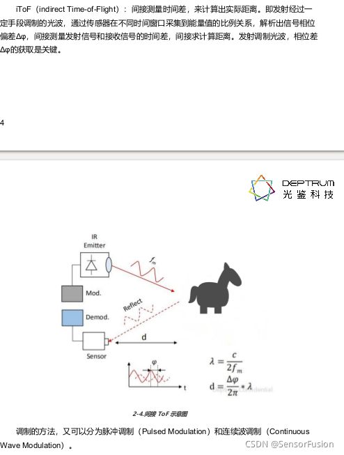
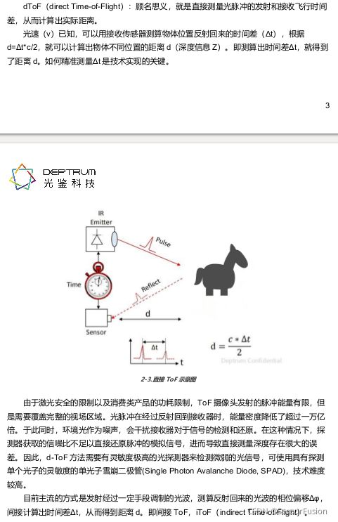
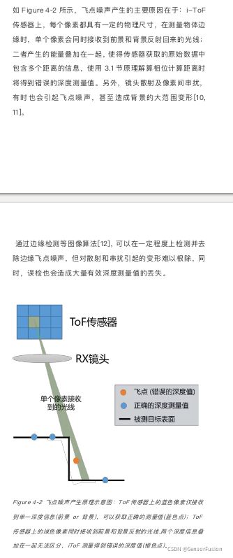
3、I-TOF是通过红外光发射器发射调制后的红外光脉冲,不停地打在物体表面,经反射后被接收器接收,通过相位的变化来计算时间差,进而结合光速计算出物体深度信息。不怎么受环境光干扰,缺点是分辨率暂时都做不高。 d-tof 间接
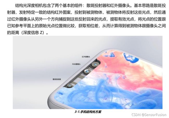
4、结构光是通过红外光发射器发射一束编码后的光斑到物体表面,光斑打在物体表面后,由于物体的形状、深度不同,光斑位置不同,通过光斑的编码信息与成像信息,进而计算出物体深度信息。结构光在室外效果很差,光斑成像容易受环境光干扰。
包括两方面工作:
1:重建点云,修改深度值
2:深度补齐,缺失深度值补全
https://blog.csdn.net/grace_yi/article/details/115555734
深度学习在深度图应用:
https://baijiahao.baidu.com/s?id=1700872402954051772&wfr=spider&for=pc
简单介绍itof原理:
https://blog.csdn.net/yegeli/article/details/119732287
