UFS 5 - UFS UIC Layer: MIPI M-PHY
UFS 5 - UFS UIC Layer: MIPI M-PHY
- 1 Termination
- 2 Drive Levels
- 3 PHY State machine
- 4 HS Burst
-
- 4.1 HS Prepare Length Control
- 4.2 HS Sync Length Control
- 5 PWM Burst
-
- 5.1 LS Prepare Length Control
- 6 Adapt
- 7 UFS PHY Attributes
UFS 1-UFS架构简介1
UFS 2 -UFS架构简介2
UFS 3 - UFS RPMB
UFS 4 - UFS Boot
1 Termination
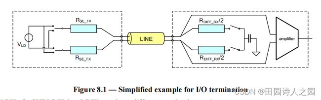
The M‐TX shall be terminated as defined in section “Termination Scheme” of the M‐PHY specification [MIPI-M-PHY].
M-TX 应按照 M-PHY 规范 [MIPI-M-PHY] 的“终止方案”部分中的定义终止。
The M‐RX shall include switchable differential termination. By default the M‐RX termination shall be off in PWM‐BURST state and may be turned on setting the proper MIPI Attribute. The termination shall be on by default in HS‐BURST state as un-terminated HS-BURST is not supported. There shall be no termination in SLEEP and STALL states. During DISABLE and HIBERNATE states M‐TX drives High‐Z while M‐RX terminates the lane by a ‘Dif‐Z keeper’. Dif‐Z keeper means M‐RX drives a weak differential zero on the lane.
M-RX 应包括可切换的差分终端。默认情况下,M-RX 终端在 PWM-BURST 状态下应关闭,并且可以通过设置适当的 MIPI 属性打开。由于不支持未终止的 HS-BURST,因此在 HS-BURST 状态下终止应默认打开。在 SLEEP 和 STALL 状态下不应有终止。在 DISABLE 和 HIBERNATE 状态期间,M-TX 驱动 High-Z,而 M-RX 通过“Dif-Z 保持器”终止通道。 Dif-Z keeper 意味着 M-RX 在车道上驱动弱差分零。
M‐RX of a SUBLINK in a LINK may have different termination settings.
LINK 中 SUBLINK 的 M-RX 可能有不同的终止设置。
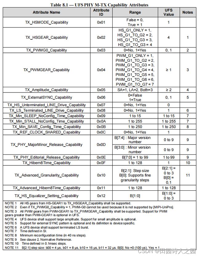
The supported termination settings are defined in the Capability Attributes in Table 8.1 and Table 8.2. The termination is controlled via the Configuration Attributes. The receiver termination resistance is defined in the M‐PHY specification.
支持的终端设置在表 8.1 和表 8.2 的能力属性中定义。终止通过配置属性控制。接收器终端电阻在 M-PHY 规范中定义。
Timings of the termination enable and disable are defined in the M‐PHY specification.
终端启用和禁用的时序在 M-PHY 规范中定义。
2 Drive Levels
The M-PHY specification defines two drive amplitudes: the large amplitude (LA) and the small amplitude (SA). The UFS interface utilizes the large amplitude (LA).
M-PHY 规范定义了两种驱动振幅:大振幅 (LA) 和小振幅 (SA)。 UFS 接口使用大振幅 (LA)。
Every M-TX in every LINK will start communication with LA after power up or reset.
每个 LINK 中的每个 M-TX 都会在上电或复位后开始与 LA 通信。
SUBLINKS in a LINK shall communicate with same amplitude.
LINK 中的 SUBLINKS 应以相同的幅度进行通信。
3 PHY State machine
The UFS interface shall implement the Type I state machine.
UFS 接口应实现 Type I 状态机。
The M‐PHY specification defines two different signaling schemes for low‐speed mode (LS-MODE): Non‐Return-to‐Zero (NRZ) and Pulse‐Width‐Modulation (PWM). The UFS interface shall utilize the PWM signaling scheme in the LS-MODE as defined by the M‐PHY specification for the State Machine Type I [MIPI M-PHY].
M-PHY 规范为低速模式 (LS-MODE) 定义了两种不同的信号方案:不归零 (NRZ) 和脉宽调制 (PWM)。 UFS 接口应使用 LS-MODE 中的 PWM 信号方案,如状态机类型 I [MIPI M-PHY] 的 M-PHY 规范所定义。
Support for LCC functionality is optional.
对 LCC 功能的支持是可选的。
4 HS Burst
A UFS device shall support the HS‐GEAR1, HS‐GEAR2, HS-GEAR3 and the HS‐GEAR4. The supported gears are indicated in the Capability Attribute Table 8.1 and Table 8.2.
UFS 设备应支持 HS-GEAR1、HS-GEAR2、HS-GEAR3 和 HS-GEAR4。支持的档位在能力属性表 8.1 和表 8.2 中指示。
SUBLINKS in a LINK may communicate with different HS‐GEAR or PWM‐GEAR.
LINK 中的 SUBLINKS 可以与不同的 HS-GEAR 或 PWM-GEAR 通信。
4.1 HS Prepare Length Control
The TX_HS_PREPARE_LENGTH M-PHY configuration attribute defines the time to move from STALL to HS‐BURST. At reset, M‐TX sets TX_HS_PREPARE_LENGTH = 15.
TX_HS_PREPARE_LENGTH M-PHY 配置属性定义了从 STALL 到 HS-BURST 的时间。复位时,M-TX 设置 TX_HS_PREPARE_LENGTH = 15。
4.2 HS Sync Length Control
The TX_HS_SYNC_LENGTH M-PHY configuration attribute defines the number of synchronization symbols before a HS Burst. In the UFS interface the synchronization sequence shall be generated by the M‐TX. Support for protocol controlled synchronization is optional. M‐TX starts at reset with TX_HS_SYNC_LENGTH = 15, in COARSE type.
TX_HS_SYNC_LENGTH M-PHY 配置属性定义了 HS Burst 之前的同步符号数。在 UFS 接口中,同步序列应由 M-TX 生成。对协议控制同步的支持是可选的。 M-TX 在复位时以 TX_HS_SYNC_LENGTH = 15 开始,粗略类型。
5 PWM Burst
A UFS device shall support the PWM‐G1. Other PWM gears are optional. The supported PWM‐GEARS are indicated in the Capability Attributes Table 8.1 and Table 8.2.
UFS 设备应支持 PWM-G1。其他 PWM 齿轮是可选的。支持的 PWM-GEARS 在能力属性表 8.1 和表 8.2 中指示。
NOTE Even if the physical layer supports PWM-G0, this gear can not be used because it is not supported by [MIPI-UniPro].
NOTE 即使物理层支持PWM-G0,也不能使用此档位,因为【MIPI-UniPro】不支持。
The PWM‐G1 shall be the active one by default after power up or reset.
PWM-G1 在上电或复位后默认为激活状态。
SUBLINKS in a LINK may communicate with different PWM‐GEAR or HS‐GEAR.
LINK 中的 SUBLINKS 可以与不同的 PWM-GEAR 或 HS-GEAR 通信。
5.1 LS Prepare Length Control
The TX_LS_PREPARE_LENGTH M-PHY configuration attribute defines the time to move from SLEEP to PWM‐BURST. At reset, M‐TX sets TX_LS_PREPARE_LENGTH = 10.
TX_LS_PREPARE_LENGTH M-PHY 配置属性定义了从 SLEEP 到 PWM-BURST 的时间。复位时,M-TX 设置 TX_LS_PREPARE_LENGTH = 10。
6 Adapt
The MIPI M-PHY version 4.1 supports a new Adapt sequence that is used to train the filter characteristics of its equalizers in the M-RX module according to the channel. An UFS device and UFS host shall implement the equalizer and the M-TX shall be able to provide the Adapt sequence to its M-RX counterpart if needed.
MIPI M-PHY 4.1 版本支持新的 Adapt 序列,用于根据通道训练 M-RX 模块中其均衡器的滤波器特性。 UFS 设备和 UFS 主机应实现均衡器,如果需要,M-TX 应能够向其 M-RX 对应方提供自适应序列。
An UFS device shall be able to initiate an Adapt sequence, but it should start it only when it is requested by the Host.
The device’s Transport Layer has the capability to initiate Adapt if there is a re-initialization request via PA-INIT.
UFS 设备应能够启动 Adapt 序列,但它应该仅在主机请求时启动它。 如果通过 PA-INIT 发出重新初始化请求,则设备的传输层能够启动 Adapt。
7 UFS PHY Attributes
The MIPI M‐PHY includes several configurable attributes. There is range of values defined for the attributes but it is left for the application to fix the actual required values inside the range. Following is the list of such attributes. The UFS application specific requirement for the values can be found from Table 8.1 and Table 8.2.
MIPI M-PHY 包括几个可配置的属性。有为属性定义的值范围,但留给应用程序来确定范围内的实际所需值。以下是此类属性的列表。可以从表 8.1 和表 8.2 中找到 UFS 应用程序特定的值要求。