Verilog——hdb3编译码的层次化设计与实现
层次化设计
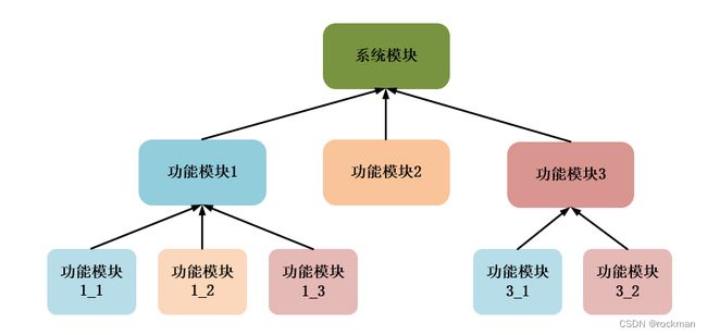
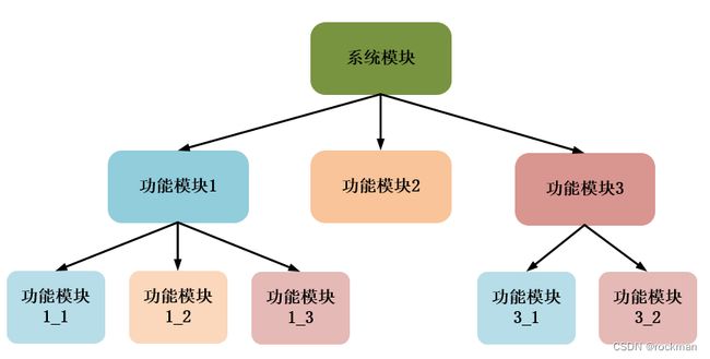
数字电路屯根据模块层次不同有两种基本的结构设计方法:自底向上(Bottom-Up)的设计方法和自顶向下(Top-Down)的设计方法。
1.自底向上
自底向上的设计是一种传统的设计方法,对设计进行逐次划分的过程是从存在的基本单元出发的,由基本单元构建高层单元,依次向上,直至构建系统。(有一些已经实现的模块搭建成一个系统)

2.自顶向下
从系统级开始,把系统分为基本单元,然后再把每个单元划分为下一层次的基本单元,一直这样做下去,直到直接可以用EDA元件库中的原件来实现为止。(先定义顶层,在分析子功能模块)

本文通过Verilog 实现HDB3编译码层次化设计及仿真。
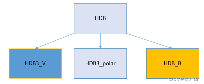
这里采用自顶向下的层次化设计,顶层模块HDB,子功能模块HDB3_V、HDB3_B、HDB3_polar。

由HDB3编码原理,可将整个功能分解为三个模块。
1.变V模块(HDB3_V)。加V编码实际是为了相处hdb3消息码中四连0的情况,当消息码中出现四个连0的时候,就会把第四个0编成V码,即0000变成000V。在hdb3的编码规则中出现B和V只是作为标识符,所以我在这里对采用了两位二进制代码来表示hdb3中0码,1码,B码,V码,分别采用00,01,10,11表示。在加V模块用Verilog HDL实现的过程中,采用时序逻辑电路,输入进来的消息码进行判决,当进来的是0码时,用一个变量进行计数,当计数到4的时候,对当前的消息码进行更换操作,即把0码换成V码(00换成11)
2.变B模块(HDB3_B)。加B模块的功能是对加V编码之后的消息码序列进行插B操作。加B操作首先是检测两个V码之间的非零是否为偶数,如果为偶数,则要把第一个0码换成B码,即000V换成B00V(00 00 00 11 换成 10 00 00 11)。
3.极性处理模块(HDB3_polar)。该模块是对插V模块和插B模块处理之后的消息码进行极性处理,根据HDB3的编码规则,相邻的两个1,B码之间的极性相反,在插V的时候,V码要与它前面第一个相邻的非零的极性相同,同时相邻的两个V码之间的极性要相反,所以在插B操作时,B码的极性与其相邻的后一位V码的极性相同,0码不做极性要求。
顶层模块HDL代码
module		HDB//顶层模块
(
	input	wire		sys_clk,
	input	wire		sys_rst,
	input	wire		in_bit,

	output	wire [1:0]	data_out,//译码输出
	output	wire [1:0]	polar_out//码极性输出
);

wire	[1:0]	net_vb;//中间变量,连接HDB3_V模块和HDB3_B模块
wire	[1:0]	net_bp;
wire	[1:0]	out_p;

HDB3_V  HDB3_V_inst //例化变V模块
(
    .      in(in_bit),
    . sys_rst(sys_rst),
    . sys_clk(sys_clk),
    .     out(net_vb)
);


HDB3_B	HDB3_B_inst  //例化变B模块
(
        .    in_b(net_vb),
        . sys_rst(sys_rst),
        . sys_clk(sys_clk),
        .   out_b(net_bp)
);


HDB3_polar	HDB3_polar_inst //例化极性处理模块
(
		.in_p		(net_bp),
		.sys_rst	(sys_rst),
		.sys_clk	(sys_clk),

		.out_polar  (out_p)
);

assign	data_out = net_bp;
assign	polar_out = out_p;


endmodule
子功能模块HDB3_V RTL代码
module HDB3_V          //0 1 b v分别对应00 01 10 11    插v
(
     input     wire              in,
     input     wire         sys_rst,
     input     wire         sys_clk,
     output    reg  [1:0]       out
);
reg [1:0] count;  //3换算成二进制位宽为2的11,对0个数进行计数
always@(posedge sys_clk or negedge sys_rst)
begin
   if(sys_rst == 1'b0)   //复位信号0有效
   begin
   count <= 2'd0;
   out <= 2'bz;
   end
   else
    begin
    if(in == 1'b1)
      begin
      out <= 2'b01;
      count<=2'd0;
      end
	else
        begin
          count <= count+1'd1;
        if(count == 2'd3) //达到连续4个0,满足条件
          begin
          out <= 2'b11;
          count <= 2'd0;
          end
          else
           out <= 2'b00;
        end
    end
end
endmodule
子功能模块HDB3_B RTL代码
module     HDB3_B						//变B模块
(
        input   wire      [1:0]     in_b,
        input   wire             sys_rst,
        input   wire             sys_clk,

        output      [1:0]          out_b
);
    wire    [1:0]   h_out;				//用来连接插B模块和插V模块的中间变量,中间变量要用wire型
    reg     [1:0]   tab_3,tab_2,tab_1,tab_0;      //四位移位寄存器
    reg             count_01;    		//对非零码个数计数
    reg     [1:0]   count_v;    		// 对V计数


 always@(posedge sys_clk or negedge sys_rst)
    if(sys_rst == 1'b0)
        count_01 <= 1'b0;
    else
    begin
        if(tab_0 == 2'b11)				//进来的是V码
            count_01 <= 1'b0;			//当V码出现时,对非零码个数计数清零
        else if(tab_0 == 2'b01)			//进来的是1码
            count_01 <= count_01 + 1'b1;//当1码出现时,计数器加1
        else
            count_01 <= count_01;		//其他情况保持不变
    end


 always@(posedge sys_clk or negedge sys_rst)
    if(sys_rst == 1'b0)
        count_v <= 1'b0;
    else
    begin
        if(tab_0 == 2'b11)
            count_v <= count_v + 1'b1;	//第一个V码出现时,计数器加1
        else
        begin
            if(count_v == 2'd2)
                count_v <= 1'b1;		//对V码计数到二时,将计数变为1。
        end
    end


//(count_01==0)&&(count_v==1)&&(tab_0==2'b11)表示两个V码之间的非零个数时偶数个
//当满足条件时输出10码,不满足输出寄存器tab_3的消息码
//这里count_01相当于一位宽的寄存器,最高计数到1,利用寄存器会溢出的特性,到计数大于1时,count_01的值就是0
//1 1 1 1 1 1,这里表示有六个1码
//1 0 1 0 1 0,这是count_01值变化。因为在第二个1时,计数器理论上加到了2,但是溢出后变为0,当下一个1出现时计数器又会计1,以此类推。
//所以奇数个1码的count_01的值就是1,偶数个1码时count_01的值就是0.
assign out_b = (count_01==0)&&(count_v==1)&&(tab_0==2'b11)? 2'b10:tab_3;


always@(posedge sys_clk)//四位移位寄存器
    begin
        tab_0 <= in_b;
        tab_1 <= tab_0;
        tab_2 <= tab_1;
        tab_3 <= tab_2;
    end

endmodule
子功能模块HDB3_polar RTL代码
module	HDB3_polar	//极性处理模块
(
		input	wire			   in_p,
		input	wire			sys_rst,
		input	wire			sys_clk,

		output	reg		[1:0]	out_polar
);
//wire	[1:0]	h_out_b;	//连接极性变化板块和插B板块的中间变量,要用wire型
reg				flag;		//标志位
reg		[1:0]	out_B;

always@(posedge sys_clk)
	begin
		out_B <= in_p;	//把in_p延时一个时钟周期
	end


always@( posedge sys_clk or negedge sys_rst )
	begin
		if(sys_rst == 1'b0)
				flag <= 0;
		else
			begin
				if( in_p == 2'b01 || in_p == 2'b10 )  //进来的消息码是1码或者B码
					begin
						if( flag == 0 )
							begin
								out_polar <= 2'b10; //极性输出负
								flag <= 1;			//标志位取反,下个极性取反
							end
						else
							begin
								out_polar <= 2'b01;	//输出极性为正
								flag <= 0;  		//标志位取反,下个极性取反
							end
					end
				else if( in_p == 2'b11 ) //进来的消息码是v码
					begin
						if( flag == 0 )
							out_polar <= 2'b01;
						else
							out_polar <= 2'b10;
					end
				else
					out_polar <= in_p;	//0码不做极性处理,输出00
			end
	end
endmodule
测试脚本(testbench)
这次只仿真了全0的情况
`timescale	1ns/1ns
module	tb_HDB();

	reg		sys_clk;
	reg		sys_rst;
	reg		in_bit;

	wire [1:0]	data_out;
	wire [1:0]	polar_out;

initial
	begin
		sys_clk = 1'b0;
		sys_rst <= 1'b0;
		in_bit = 1'b1;
		#10
		sys_rst <= 1'b1;
	end

always	#5		sys_clk = ~sys_clk;

  always
  begin
	//#10		in_bit <= {$random} % 2;随机生成二进制数,随机码
    #10  in_bit <= 1'b0; //1  0  1  1
    #10  in_bit <= 1'b0; //1  0  0  0
    #10  in_bit <= 1'b0; //1  0  1  0
    #10  in_bit <= 1'b0; //1  0  0  0
    #10  in_bit <= 1'b0; //1  0  0  0
	#10  in_bit <= 1'b0; //1  0  0  0
	#10  in_bit <= 1'b0; //1  0  0  0
	#10  in_bit <= 1'b0; //1  0  0  0
	#10  in_bit <= 1'b0; //1  0  0  0
	#10  in_bit <= 1'b0; //1  0  0  0
    #10  in_bit <= 1'b0; //1  0  1  0
    #10  in_bit <= 1'b0; //1  0  0  0
    #10  in_bit <= 1'b0; //1  0  1  1
    #10  in_bit <= 1'b0; //1  0  0  0
    #10  in_bit <= 1'b0; //1  0  1  0
	#10  in_bit <= 1'b0; //1  0  1  0
    #10  in_bit <= 1'b0; //1  0  1  0
    #10  in_bit <= 1'b0; //1  0  1  0
	#10  in_bit <= 1'b0;
	#10  in_bit <= 1'b0;
  end

HDB HDB_inst
(
	.sys_clk	(sys_clk),
	.sys_rst	(sys_rst),
	.in_bit		(in_bit),

	.data_out	(data_out),
	.polar_out  (polar_out)
);

endmodule
modulesim仿真结果
