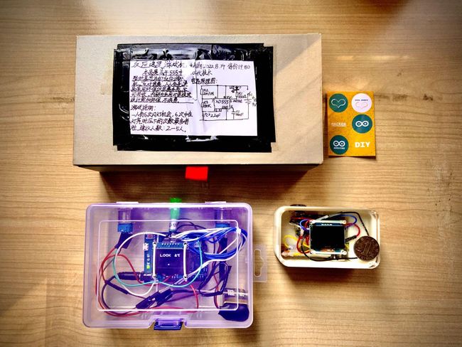
时间间隔感测试器2.0
最近在学习SOLIDWORKS 2021,想找一个之前已经做好的东西升级一下外观,做的好看一点。之前做的时间间隔感测试器正好符合这个条件:模块不多,稍微改进即可缩小尺寸,变成可以放在手里的掌机了!
1.外壳
正好做IMU的时候还剩下了几片树莓派picow,也可以用arduino ide开发,可以利用利用。于是就按着树莓派pico w,加1.3寸屏,加1.6cm按钮,加3.7v电池盒的尺寸画了个盒子。中间没有什么太大的坑,就是SOLIDWORKS比较耗电脑资源,中途电脑有一定的概率死机或者蓝屏,一定要记得即使保存,否则辛辛苦苦花了几个小时的图纸说没就没了,谁都会崩溃的。再就是尺寸一定要确定好,单位对不对,一个打印的零件可不便宜。
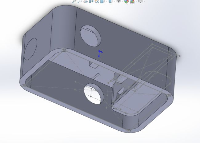
我画的外壳
到了下单的时候,要把图纸另存为stl文件,再发给客服。3D打印只需要stl文件就可以了,但亚克力的话还得和客服确定是否可以通过stl文件来切割亚克力板,不行的话还得再转成工程图。转工程图的时候一定要确定单位是什么,不要出现过定义的尺寸。否则很容易就切错了厚度。像我就是一个很好的例子,亚克力板的厚度旁边有一个过定义的尺寸,是1cm……于是原本是4mm的亚克力上盖就变成了1cm厚的亚克力板砖了
下面是我的图纸,大家可以参考一下,但可能还需要根据自己的实际情况改进一些部分:
外壳图纸-电池盖图纸
外壳图纸-主体盒子图纸
外壳图纸-亚克力上盖图纸
2.时间间隔感测试器2.0的改进
这次更换了开发板,也更换了oled屏,从资料十分稀少的1.3寸sh1106 7针spi屏换成了1.3寸sh1106 4针iic屏。一开始本着“这次是做外壳”的想法,使用了之前用的1.3寸sh1106 7针spi屏的显示库,只是在初始化的时候把spi换成了iic,然后......点不亮,之后发现这个库只适用于uno......但不要紧,还有万能的u8g2显示库,指定了pico w的iic引脚,然后......还是点不亮。之后上网查,发现了树莓派pico(rp2040)只能用一个叫“OneBitDisplay“的闻所未闻的显示库来点亮,这是库自带的例程:
//
// OneBitDisplay library multi-display demo
//
// Demonstrates how to initialize and use multiple displays
//
#include

// Use -1 for the Wire library default pins
// or specify the pin numbers to use with the Wire library or bit banging on any GPIO pins
// These are reversed because I did straight-through wiring for my SSD1306
// and it has the 4-pin header as GND,VCC,SCL,SDA, but the GROVE connector is
// GND,VCC,SDA,SCL
#define GROVE_SDA_PIN 32
#define GROVE_SCL_PIN 26
// These are the pin numbers for the M5Stack Atom default I2C
#define SDA_PIN 21
#define SCL_PIN 22
// Set this to -1 to disable or the GPIO pin number connected to the reset
// line of your display if it requires an external reset
#define RESET_PIN -1
// let ss_oled figure out the display address
#define OLED_ADDR -1
// don't rotate the display
#define FLIP180 0
// don't invert the display
#define INVERT 0
// Bit-Bang the I2C bus
#define USE_HW_I2C 0

// Change these if you're using different OLED displays
#define MY_OLED1 OLED_128x64
#define MY_OLED2 OLED_64x32

// 2 copies of the SSOLED structure. Each structure is about 56 bytes
// There is no limit to the number of simultaneous displays which can be controlled by ss_oled
OBDISP obd[2];

void setup() {
char *msgs[] = {(char *)"SSD1306 @ 0x3C", (char *)"SSD1306 @ 0x3D",(char *)"SH1106 @ 0x3C",(char *)"SH1106 @ 0x3D"};
int rc;
// The I2C SDA/SCL pins set to -1 means to use the default Wire library
// If pins were specified, they would be bit-banged in software
// This isn't inferior to hw I2C and in fact allows you to go faster on certain CPUs
// The reset pin is optional and I've only seen it needed on larger OLEDs (2.4")
//    that can be configured as either SPI or I2C
//
// obdI2CInit(OBDISP *, type, oled_addr, rotate180, invert, bWire, SDA_PIN, SCL_PIN, RESET_PIN, speed)

rc = obdI2CInit(&obd[0], MY_OLED1, OLED_ADDR, FLIP180, INVERT, 1, SDA_PIN, SCL_PIN, RESET_PIN, 400000L); // use standard I2C bus at 400Khz
  if (rc != OLED_NOT_FOUND)
  {
    obdFill(&obd[0], 0, 1);
    obdWriteString(&obd[0], 0,0,0,msgs[rc], FONT_8x8, 0, 1);
    obdWriteString(&obd[0], 0,8,3,(char *)"Display", FONT_16x16, 0, 1);
    obdWriteString(&obd[0], 0,56,6,(char *)"0", FONT_16x16, 0, 1);
  }
rc = obdI2CInit(&obd[1], MY_OLED2, OLED_ADDR, FLIP180, INVERT, 0, GROVE_SDA_PIN, GROVE_SCL_PIN, RESET_PIN, 400000L); // use standard I2C bus at 400Khz
  if (rc != OLED_NOT_FOUND)
  {
    obdFill(&obd[1], 0, 1);
    obdSetTextWrap(&obd[1], 1);
    obdWriteString(&obd[1], 0,0,0,msgs[rc], FONT_6x8, 0, 1);
    obdWriteString(&obd[1], 0,4,2,(char *)"Display", FONT_8x8, 0, 1);
    obdWriteString(&obd[1], 0,28,3,(char *)"1", FONT_8x8, 0, 1);
  }
} /* setup() */

void loop() {
  // put your main code here, to run repeatedly:

} /* loop() */
这个显示库的例程比较复杂,不像u8g2那么简洁,第一眼很难看出每个参数是干什么的,所以我们来详解一下:
#include 引入OneBitDisplay显示库。
// GND,VCC,SDA,SCL(1)
#define GROVE_SDA_PIN 32
#define GROVE_SCL_PIN 26
// GND,VCC,SDA,SCL(2)
#define SDA_PIN 21
#define SCL_PIN 22
定义两组iic引脚。
// line of your display if it requires an external reset
#define RESET_PIN -1
定义reset引脚,因为大多数iic显示屏未引出reset引脚,所这里填默认值-1.
// let ss_oled figure out the display address
#define OLED_ADDR -1
iic地址,这里填默认值。
// don't rotate the display
#define FLIP180 0
是否翻转显示,这里不翻转显示
// don't invert the display
#define INVERT 0
是否反色显示,这里不反色显示。
// Bit-Bang the I2C bus
#define USE_HW_I2C 0
是否手动指定iic引脚,这里手动指定。
// Change these if you're using different OLED displays
#define MY_OLED1 OLED_128x64
#define MY_OLED2 OLED_64x32
定义两个屏,一个为12864,一个为12832。
obdI2CInit(&obd[0], MY_OLED1, OLED_ADDR, FLIP180, INVERT, 1, SDA_PIN, SCL_PIN, RESET_PIN, 400000L);iic初始化语句,其中:
&obd[0]
指定一个屏。
400000L
指定iic速度。
obdWriteString(&obd[1], 0,4,2,(char *)"Display", FONT_8x8, 0, 1);显示函数,语法为:
obdWriteString(屏【1】, 滚动,x轴,y轴,(char *)"文字", 字体, 反色, 绘制在缓冲区或屏幕);字体有:
FONT_6x8
FONT_8x8
FONT_12x16
FONT_16x16
FONT_16x32
了解了各个函数的用法之后我们就可以写出自己的显示程序了,这是我的显示例程:
//lib
#include

// These are the pin numbers for the M5Stack Atom default I2C
#define SDA_PIN 0
#define SCL_PIN 1
// line of your display if it requires an external reset
#define RESET_PIN -1
// let ss_oled figure out the display address
#define OLED_ADDR -1
// don't rotate the display
#define FLIP180 0
// don't invert the display
#define INVERT 0
// Bit-Bang the I2C bus
#define USE_HW_I2C 0
//oled
OBDISP obd;
//OLED displays
#define MY_OLED OLED_128x64

int n=500;
char buf[10];

void setup() {
  // put your setup code here, to run once:
  sprintf(buf, "H%d", n);
  // use standard I2C bus at 400Khz
  obdI2CInit(&obd, MY_OLED, OLED_ADDR, FLIP180, INVERT, 1, SDA_PIN, SCL_PIN, RESET_PIN, 600000L);
  obdFill(&obd, 0, 1);
  obdWriteString(&obd, 0, 8, 3,(char *)"HAND SPEED TEST       ", FONT_8x8, 1, 1);
  delay(2000);
  obdWriteString(&obd, 0, 8, 3,(char *)"Ver:  2.1             ", FONT_8x8, 1, 1);
  delay(2000);
  obdWriteString(&obd, 0, 8, 3,(char *)"Date: 20221229        ", FONT_8x8, 1, 1);
  delay(2000);
  obdWriteString(&obd, 0, 8, 3,(char *)"                      ", FONT_8x8, 1, 1);
  obdWriteString(&obd, 0, 10,4,(char *)" GO!!! ", FONT_16x16, 1, 1);
  delay(2000);
  obdWriteString(&obd, 0, 10,4,(char *)"                 ", FONT_16x16, 1, 1);
  obdWriteString(&obd, 0, 8, 2,(char *)"Your hand speed ", FONT_8x8, 1, 1);
  obdWriteString(&obd, 0, 8,18,(char *)"is", FONT_8x8, 1, 1);
  obdWriteString(&obd, 0, 8, 40,(char *)&buf, FONT_12x16, 1, 1);
  obdWriteString(&obd, 0, 58, 40,(char *)"ms", FONT_12x16, 1, 1);
  delay(2000);
  //obdWriteString(&obd, 0, 8, 40,(char *)"                 ", FONT_12x16, 1, 1);
  //obdWriteString(&obd, 0, 8, 40,(char *)">1s", FONT_12x16, 1, 1);
}

void loop() {
  // put your main code here, to run repeatedly:
  //none
}
其中,我自己加了一个显示变量的功能:
//lib
#include

int n=500;
char buf[10];

void setup()
{
  sprintf(buf, " %d", n);
  // use standard I2C bus at 400Khz
  obdI2CInit(&obd, MY_OLED, OLED_ADDR, FLIP180, INVERT, 1, SDA_PIN, SCL_PIN, RESET_PIN, 60000  0L);
  obdFill(&obd, 0, 1);
  obdWriteString(&obd, 0, 8, 40,(char *)&buf, FONT_12x16, 1, 1);
}

void loop()
{
  //none
}
通过将变量放入缓冲区中,将其转化为ASCII码,再调用字库将其显示出来。
除显示以外的其他功能几乎没有改变,有关于除显示以外的其他功能详见我的另一篇博客:
时间间隔感测试器(下):Arduino uno
这是采用”OneBitDisplay”显示库的时间间隔感测试器2.0的程序:
#include

// These are the pin numbers for the M5Stack Atom default I2C
#define SDA_PIN 0
#define SCL_PIN 1
// line of your display if it requires an external reset
#define RESET_PIN -1
// let ss_oled figure out the display address
#define OLED_ADDR -1
// don't rotate the display
#define FLIP180 0
// don't invert the display
#define INVERT 0
// Bit-Bang the I2C bus
#define USE_HW_I2C 0
//oled
OBDISP obd;
//OLED displays
#define MY_OLED OLED_128x64

char buf[10];

const int buttonpin = 3;
const int ledpin = 25;
const int vcc = 28;
int buttonpintwo;
int startsignal;
unsigned long timebox;
unsigned long rtime1;
unsigned long rtime2;
int key;

void setup()   {
  // Start OLED
  obdI2CInit(&obd, MY_OLED, OLED_ADDR, FLIP180, INVERT, 1, SDA_PIN, SCL_PIN, RESET_PIN, 600000L);

  obdFill(&obd, 0, 1);
  obdWriteString(&obd, 0, 8, 10,(char *)"HAND SPEED TEST         ", FONT_8x8, 1, 1);
  obdWriteString(&obd, 0, 8, 30,(char *)"Ver:  2.2               ", FONT_8x8, 1, 1);
  obdWriteString(&obd, 0, 8, 50,(char *)"Date: 20230112          ", FONT_8x8, 1, 1);
  delay (5000);
  obdWriteString(&obd, 0, 8, 10,(char *)"                            ", FONT_8x8, 1, 1);
  obdWriteString(&obd, 0, 8, 30,(char *)"                           ", FONT_8x8, 1, 1);
  obdWriteString(&obd, 0, 8, 50,(char *)"                           ", FONT_8x8, 1, 1);

  pinMode (buttonpin,INPUT);
  pinMode (ledpin,OUTPUT);
  pinMode (vcc,OUTPUT);
  digitalWrite (vcc,HIGH);
  startsignal=1;
  obdWriteString(&obd, 0, 20,8,(char *)" GAME", FONT_16x16, 1, 1);
  obdWriteString(&obd, 0, 12,32,(char *)" START! ", FONT_16x16, 1, 1);
  delay (5000);
}


void loop() {
  //obdFill(&obd, 0, 1);
  if(startsignal==1)
  {
      obdWriteString(&obd, 0, 28,8,(char *)"                     ", FONT_16x16, 1, 1);
      obdWriteString(&obd, 0, 20,32,(char *)"                    ", FONT_16x16, 1, 1);
      obdWriteString(&obd, 0, 12,24,(char *)" GO!!! ", FONT_16x16, 1, 1);
      rtime1=millis();
  }
  startsignal=0;
  buttonpintwo=digitalRead(buttonpin);
  if(buttonpintwo==HIGH){
    rtime2=millis();
    timebox=rtime2-rtime1;
    sprintf(buf, " %d", timebox);
    obdWriteString(&obd, 0, 12,24,(char *)"                 ", FONT_16x16, 1, 1);
    obdWriteString(&obd, 0, 8, 2,(char *)"Your hand speed  ", FONT_8x8, 1, 1);
    obdWriteString(&obd, 0, 8, 18,(char *)"is", FONT_8x8, 1, 1);
    if(timebox<999)
    {
      obdWriteString(&obd, 0, 8, 40,(char *)&buf, FONT_12x16, 1, 1);
      obdWriteString(&obd, 0, 58, 40,(char *)"ms", FONT_12x16, 1, 1);
    }
    else{
      obdWriteString(&obd, 0, 8, 40,(char *)">1s", FONT_12x16, 1, 1);
    }
    delay(5000);

    startsignal=1;
    sprintf(buf, " %d", 0);
  }
}
3.rp2040上传出错解决方案
本节主要是有关于rp2040上传出错的一些内容,如果不使用rp2040或是没有碰到这类问题的可以跳过。
方法一
如果怀疑是pc端问题:
重启电脑
重启arduino ide
重新下载开发板驱动
方法二
1.搜索设备管理器:

2.找到“端口(COM和LPT)":

3.点开“端口(COM和LPT)",卸载掉开发板:
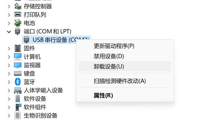
4.重新进入arduino ide选择串口,点击上传:
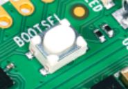
方法三
按住BOOTSEL键,进入USB 大容量存储启动模式:
拖放擦除flash的uf2文件:
拖放初始uf2文件:
重新进入arduino ide选择串口,点击上传:
方法四
按住BOOTSEL键,插拔连接开发板和电脑的usb线缆:

重新进入arduino ide选择串口,点击上传:
总结
当你发现你的朋友总是抢到红包的时候,你可以拿出这个,看看他是否用了抢红包外挂......绝无作弊可能,超厚机箱物理隔绝。没有网络接口,没有usb接口,没有串口,所有接口与外界物理隔绝!电池供电,充电五分钟,待机5个月!