STM32(HAL库)驱动AD8232心率传感器
目录
1、简介
2、CubeMX初始化配置
2.1 基础配置
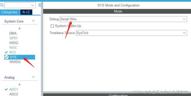
2.1.1 SYS配置
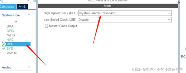
2.1.2 RCC配置
2.2 ADC外设配置
2.3 串口外设配置
2.4 GPIO配置
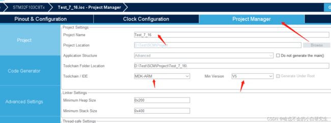
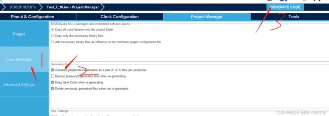
2.5 项目生成
3、KEIL端程序整合
3.1 串口重映射
3.2 ADC数据采集
3.3 主函数代码整合
4 硬件连接
5 效果展示
1、简介
本文通过STM32F103C8T6单片机通过HAL库方式对AD8232心率传感器进行数据的读取,并通过串口来进行显示。
2、CubeMX初始化配置
2.1 基础配置
2.1.1 SYS配置
2.1.2 RCC配置
2.2 ADC外设配置

2.3 串口外设配置

2.4 GPIO配置

2.5 项目生成
3、KEIL端程序整合
3.1 串口重映射
具体步骤:stm32(HAL库)使用printf函数打印到串口
3.2 ADC数据采集
首先在adc.c最下方添加ADC采集程序,如下所示:

代码如下:
uint16_t ADC_IN_1(void) //ADC采集程序
{
	HAL_ADC_Start(&hadc1);//开始ADC采集
	HAL_ADC_PollForConversion(&hadc1,500);//等待采集结束
	if(HAL_IS_BIT_SET(HAL_ADC_GetState(&hadc1), HAL_ADC_STATE_REG_EOC))//读取ADC完成标志位
	{
		return HAL_ADC_GetValue(&hadc1);//读出ADC数值
	}
	return 0;
}
接着在adc.h中进行函数声明,如下图所示:

uint16_t ADC_IN_1(void);//ADC采集程序3.3 主函数代码整合
首先在mian.h进行宏定义,如下所示:
#define LD0 HAL_GPIO_ReadPin(LD__GPIO_Port, LD__Pin)
#define LD1 HAL_GPIO_ReadPin(LD_B13_GPIO_Port, LD_B13_Pin)
首先定义变量接受ADC_IN_1()采集数据,如下所示:
uint8_t adc_AD8232;接着在主函数While循环上方进行ADC采样校准,如下所示:
HAL_ADCEx_Calibration_Start(&hadc1);//ADC采样校准最后while循环中进行数据打印,如下所示:
while (1)
  {
		if(LD0==1||LD1==1){
			printf("error");
		}
		else{
				adc_AD8232 = ADC_IN_1()/10;
				printf("%d",adc_AD8232);
		}
		HAL_Delay(500);
    /* USER CODE END WHILE */

    /* USER CODE BEGIN 3 */
  }
main.c如下所示:
/* USER CODE BEGIN Header */
/**
  ******************************************************************************
  * @file           : main.c
  * @brief          : Main program body
  ******************************************************************************
  * @attention
  *
  * Copyright (c) 2023 STMicroelectronics.
  * All rights reserved.
  *
  * This software is licensed under terms that can be found in the LICENSE file
  * in the root directory of this software component.
  * If no LICENSE file comes with this software, it is provided AS-IS.
  *
  ******************************************************************************
  */
/* USER CODE END Header */
/* Includes ------------------------------------------------------------------*/
#include "main.h"
#include "adc.h"
#include "usart.h"
#include "gpio.h"

/* Private includes ----------------------------------------------------------*/
/* USER CODE BEGIN Includes */
uint8_t adc_AD8232;
/* USER CODE END Includes */

/* Private typedef -----------------------------------------------------------*/
/* USER CODE BEGIN PTD */

/* USER CODE END PTD */

/* Private define ------------------------------------------------------------*/
/* USER CODE BEGIN PD */
/* USER CODE END PD */

/* Private macro -------------------------------------------------------------*/
/* USER CODE BEGIN PM */

/* USER CODE END PM */

/* Private variables ---------------------------------------------------------*/

/* USER CODE BEGIN PV */

/* USER CODE END PV */

/* Private function prototypes -----------------------------------------------*/
void SystemClock_Config(void);
/* USER CODE BEGIN PFP */

/* USER CODE END PFP */

/* Private user code ---------------------------------------------------------*/
/* USER CODE BEGIN 0 */

/* USER CODE END 0 */

/**
  * @brief  The application entry point.
  * @retval int
  */
int main(void)
{
  /* USER CODE BEGIN 1 */

  /* USER CODE END 1 */

  /* MCU Configuration--------------------------------------------------------*/

  /* Reset of all peripherals, Initializes the Flash interface and the Systick. */
  HAL_Init();

  /* USER CODE BEGIN Init */

  /* USER CODE END Init */

  /* Configure the system clock */
  SystemClock_Config();

  /* USER CODE BEGIN SysInit */

  /* USER CODE END SysInit */

  /* Initialize all configured peripherals */
  MX_GPIO_Init();
  MX_ADC1_Init();
  MX_USART1_UART_Init();
  /* USER CODE BEGIN 2 */

  HAL_ADCEx_Calibration_Start(&hadc1);//ADC采样校准
  /* USER CODE END 2 */

  /* Infinite loop */
  /* USER CODE BEGIN WHILE */
  while (1)
  {
		if(LD0==1||LD1==1){
			printf("error");
		}
		else{
				adc_AD8232 = ADC_IN_1()/10;
				printf("%d",adc_AD8232);
		}
		HAL_Delay(500);
    /* USER CODE END WHILE */

    /* USER CODE BEGIN 3 */
  }
  /* USER CODE END 3 */
}

/**
  * @brief System Clock Configuration
  * @retval None
  */
void SystemClock_Config(void)
{
  RCC_OscInitTypeDef RCC_OscInitStruct = {0};
  RCC_ClkInitTypeDef RCC_ClkInitStruct = {0};
  RCC_PeriphCLKInitTypeDef PeriphClkInit = {0};

  /** Initializes the RCC Oscillators according to the specified parameters
  * in the RCC_OscInitTypeDef structure.
  */
  RCC_OscInitStruct.OscillatorType = RCC_OSCILLATORTYPE_HSE;
  RCC_OscInitStruct.HSEState = RCC_HSE_ON;
  RCC_OscInitStruct.HSEPredivValue = RCC_HSE_PREDIV_DIV1;
  RCC_OscInitStruct.HSIState = RCC_HSI_ON;
  RCC_OscInitStruct.PLL.PLLState = RCC_PLL_ON;
  RCC_OscInitStruct.PLL.PLLSource = RCC_PLLSOURCE_HSE;
  RCC_OscInitStruct.PLL.PLLMUL = RCC_PLL_MUL9;
  if (HAL_RCC_OscConfig(&RCC_OscInitStruct) != HAL_OK)
  {
    Error_Handler();
  }

  /** Initializes the CPU, AHB and APB buses clocks
  */
  RCC_ClkInitStruct.ClockType = RCC_CLOCKTYPE_HCLK|RCC_CLOCKTYPE_SYSCLK
                              |RCC_CLOCKTYPE_PCLK1|RCC_CLOCKTYPE_PCLK2;
  RCC_ClkInitStruct.SYSCLKSource = RCC_SYSCLKSOURCE_PLLCLK;
  RCC_ClkInitStruct.AHBCLKDivider = RCC_SYSCLK_DIV1;
  RCC_ClkInitStruct.APB1CLKDivider = RCC_HCLK_DIV2;
  RCC_ClkInitStruct.APB2CLKDivider = RCC_HCLK_DIV1;

  if (HAL_RCC_ClockConfig(&RCC_ClkInitStruct, FLASH_LATENCY_2) != HAL_OK)
  {
    Error_Handler();
  }
  PeriphClkInit.PeriphClockSelection = RCC_PERIPHCLK_ADC;
  PeriphClkInit.AdcClockSelection = RCC_ADCPCLK2_DIV6;
  if (HAL_RCCEx_PeriphCLKConfig(&PeriphClkInit) != HAL_OK)
  {
    Error_Handler();
  }
}

/* USER CODE BEGIN 4 */

/* USER CODE END 4 */

/**
  * @brief  This function is executed in case of error occurrence.
  * @retval None
  */
void Error_Handler(void)
{
  /* USER CODE BEGIN Error_Handler_Debug */
  /* User can add his own implementation to report the HAL error return state */
  __disable_irq();
  while (1)
  {
  }
  /* USER CODE END Error_Handler_Debug */
}

#ifdef  USE_FULL_ASSERT
/**
  * @brief  Reports the name of the source file and the source line number
  *         where the assert_param error has occurred.
  * @param  file: pointer to the source file name
  * @param  line: assert_param error line source number
  * @retval None
  */
void assert_failed(uint8_t *file, uint32_t line)
{
  /* USER CODE BEGIN 6 */
  /* User can add his own implementation to report the file name and line number,
     ex: printf("Wrong parameters value: file %s on line %d\r\n", file, line) */
  /* USER CODE END 6 */
}
#endif /* USE_FULL_ASSERT */
4 硬件连接
VCC ---- 3.3V
GND ---- GND
OUTPUT ---- PA1(ADC引脚)
LD+ ---- PB12(GPIO输入)
LD- ---- PB13(GPIO输入)
SDA ---- PB14(GPIO高电平输出)
注意:
LOD-,LOD+接到身上的三个电极,当接口脱落,这两个口某一个口会变为高电平。
SDN 开启和关闭模块功能,接到GPIO输出口,给它高电平则模块工作,给低电平则不工作。
5 效果展示
传感器接到身上,效果如下:

传感器接口脱落,效果如下:

上文如有错误,恳请各位大佬指正。