37款传感器与执行器的提法,在网络上广泛流传,其实Arduino能够兼容的传感器模块肯定是不止这37种的。鉴于本人手头积累了一些传感器和执行器模块,依照实践出真知(一定要动手做)的理念,以学习和交流为目的,这里准备逐一动手尝试系列实验,不管成功(程序走通)与否,都会记录下来—小小的进步或是搞不掂的问题,希望能够抛砖引玉。
【Arduino】168种传感器模块系列实验(资料代码+仿真编程+图形编程)
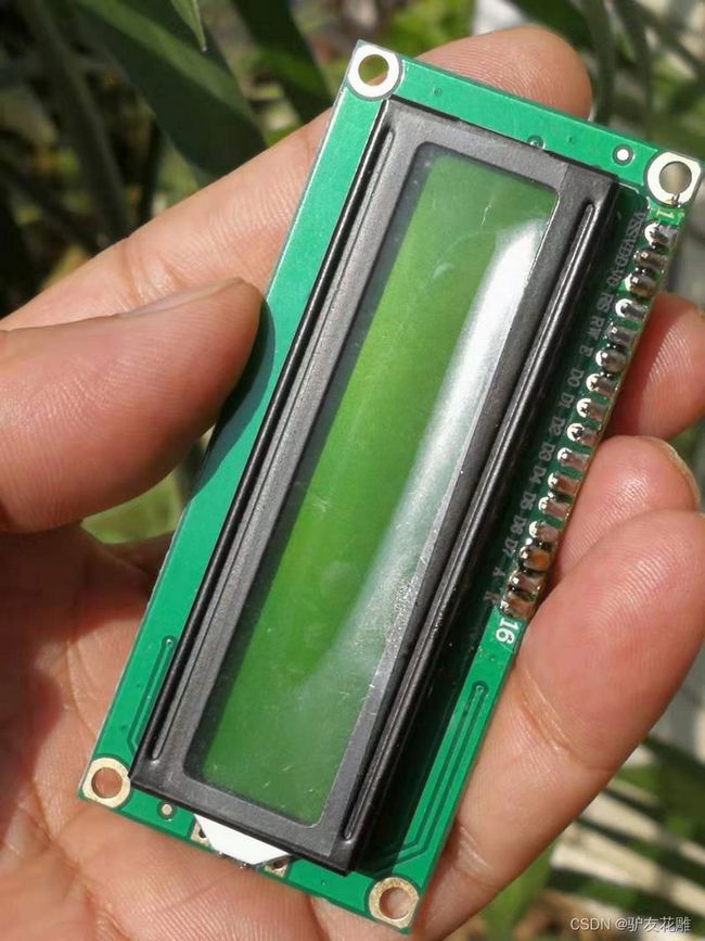
实验八十五:LCD1602液晶显示屏1602A模块 蓝屏黄绿屏灰屏5V 3.3V焊排针 IIC/I2C
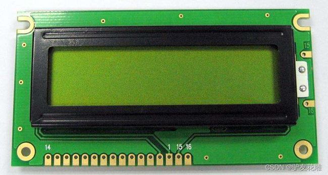
也叫1602字符型液晶,它是一种专门用来显示字母、数字、符号等的点阵型液晶模块。它由若干个5X7或者5X11等点阵字符位组成,每个点阵字符位都可以显示一个字符,每位之间有一个点距的间隔,每行之间也有间隔,起到了字符间距和行间距的作用,正因为如此所以它不能很好地显示图形(用自定义CGRAM,显示效果也不好)。1602LCD是指显示的内容为16X2,即可以显示两行,每行16个字符液晶模块(显示字符和数字)。市面上字符液晶大多数是基于HD44780液晶芯片的,控制原理是完全相同的,因此基于HD44780写的控制程序可以很方便地应用于市面上大部分的字符型液晶。
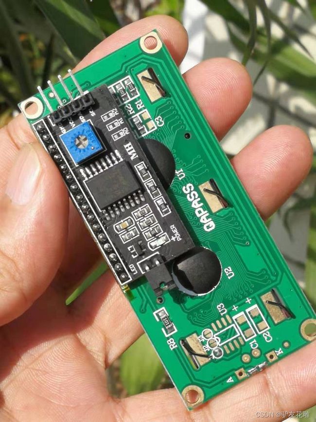
IC/I2C接口LCD1602转接板
控制板IO口只有20个,加些传感器、SD卡啥的,继电器等模块多了,IO口就不够用了,原来的1602屏至少需要7个IO口才能驱动起来,这个模块可以帮你省5个IO口。
参数
1.供电电压:+5V
2.支持I2C协议
3.具有背光灯,和对比度调节电位器
4.4线输出更简单
5.设备地址:0x27
【Arduino】168种传感器模块系列实验(资料代码+仿真编程+图形编程)
实验八十八: LCD1602A液晶屏5V显示模块(IIC/I2C接口)
项目二十:循环显示常用的键码
实验开源代码
/*
【Arduino】168种传感器模块系列实验(资料代码+仿真编程+图形编程)
实验八十八: LCD1602A液晶屏5V显示模块(IIC/I2C接口)
项目二十:循环显示常用的键码
Arduino------LCD1602
5V-------------VCC
GND-----------GND
A4-----------SDA IIC 数据线
A5-----------SCL IIC 时钟线
*/
#include
#include
#if defined(ARDUINO) && ARDUINO >= 100
#define printByte(args) write(args);
#else
#define printByte(args) print(args,BYTE);
#endif
uint8_t bell[8] = {0x4, 0xe, 0xe, 0xe, 0x1f, 0x0, 0x4};
uint8_t note[8] = {0x2, 0x3, 0x2, 0xe, 0x1e, 0xc, 0x0};
uint8_t clock[8] = {0x0, 0xe, 0x15, 0x17, 0x11, 0xe, 0x0};
uint8_t heart[8] = {0x0, 0xa, 0x1f, 0x1f, 0xe, 0x4, 0x0};
uint8_t duck[8] = {0x0, 0xc, 0x1d, 0xf, 0xf, 0x6, 0x0};
uint8_t check[8] = {0x0, 0x1, 0x3, 0x16, 0x1c, 0x8, 0x0};
uint8_t cross[8] = {0x0, 0x1b, 0xe, 0x4, 0xe, 0x1b, 0x0};
uint8_t retarrow[8] = { 0x1, 0x1, 0x5, 0x9, 0x1f, 0x8, 0x4};
// 对于 16 个字符和 2 行显示,将 LCD 地址设置为 0x27
LiquidCrystal_I2C lcd(0x27, 20, 4);
void setup() {
lcd.init(); // 初始化液晶显示器
lcd.backlight();
lcd.createChar(0, bell);
lcd.createChar(1, note);
lcd.createChar(2, clock);
lcd.createChar(3, heart);
lcd.createChar(4, duck);
lcd.createChar(5, check);
lcd.createChar(6, cross);
lcd.createChar(7, retarrow);
lcd.home();
lcd.print("Hello world...");
lcd.setCursor(0, 1);
lcd.print(" i ");
lcd.printByte(3);
lcd.print(" arduinos!");
delay(1000);
displayKeyCodes();
}
// 显示所有键码
void displayKeyCodes(void) {
uint8_t i = 0;
while (1) {
lcd.clear();
lcd.print("Codes 0x"); lcd.print(i, HEX);
lcd.print("-0x"); lcd.print(i + 16, HEX);
lcd.setCursor(0, 1);
for (int j = 0; j < 16; j++) {
lcd.printByte(i + j);
}
i += 16;
delay(1000);
}
}
void loop() {
}
【Arduino】168种传感器模块系列实验(资料代码+仿真编程+图形编程)
实验八十八: LCD1602A液晶屏5V显示模块(IIC/I2C接口)
项目二十:循环显示常用的键码
实验场景图
【Arduino】168种传感器模块系列实验(资料代码+仿真编程+图形编程)
实验九十一: 1号霍尔水流量传感器 直饮机流量监控模块
项目十:用LCD1602A屏显示水流量传感器输出
实验开源代码
/*
【Arduino】168种传感器模块系列实验(资料代码+仿真编程+图形编程)
实验九十一: 1号霍尔水流量传感器 直饮机流量监控模块
项目十:用LCD1602A屏显示水流量传感器输出
实验接线:Uno D2接流量传感器OUT
Arduino------LCD1602
5V-------------VCC
GND-----------GND
A4-----------SDA IIC 数据线
A5-----------SCL IIC 时钟线
*/
#include
#include
LiquidCrystal_I2C lcd(0x27, 16, 2);
unsigned char flow_sensor_pin = 2;
unsigned int flow_per_min;
unsigned long current_time;
unsigned long cloop_time;
volatile int sensor_pulses;
void setup() {
Serial.begin(9600);
lcd.init(); //初始化LCD
lcd.backlight(); //打开背光
sei();
lcd.begin(16, 2);
lcd.clear();
lcd.setCursor(0, 0);
lcd.print(" Flow Meter ");
pinMode(flow_sensor_pin, INPUT);
digitalWrite(flow_sensor_pin, HIGH);
attachInterrupt(0, pulses_measure, RISING);
current_time = millis();
cloop_time = current_time;
}
void loop ()
{
current_time = millis();
if (current_time >= (cloop_time + 1000))
{
cloop_time = current_time;
flow_per_min = (sensor_pulses / 7.5);
sensor_pulses = 0;
Serial.print(flow_per_min, DEC);
Serial.println(" L/MIN");
lcd.setCursor(0, 1);
lcd.print(" ");
lcd.setCursor(0, 1);
lcd.print(" Flow:");
lcd.print(flow_per_min, DEC);
lcd.print(" L/MIN");
delay(100);
}
}
void pulses_measure () {
sensor_pulses++;
}
【Arduino】168种传感器模块系列实验(资料代码+仿真编程+图形编程)
实验九十一: 1号霍尔水流量传感器 直饮机流量监控模块
项目十:用LCD1602A屏显示水流量传感器输出
实验场景图
【Arduino】168种传感器模块系列实验(资料代码+仿真编程+图形编程) 实验八十八: LCD1602A液晶屏5V显示模块(IIC/I2C接口)
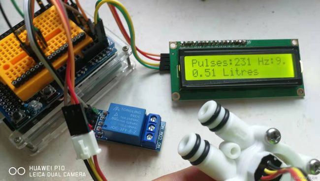
项目二十一:水流量传感器、5V继电器模块和LCD1602 I2C模块
实验接线:Uno D2接流量传感器OUT,继电器接D4
Arduino------LCD1602
5V-------------VCC
GND-----------GND
A4-----------SDA IIC 数据线
A5-----------SCL IIC 时钟线
实验开源代码
/*
【Arduino】168种传感器模块系列实验(资料代码+仿真编程+图形编程)
实验八十八: LCD1602A液晶屏5V显示模块(IIC/I2C接口)
项目二十一:水流量传感器、5V继电器模块和LCD1602 I2C模块
实验接线:Uno D2接流量传感器OUT,继电器接D4
Arduino------LCD1602
5V-------------VCC
GND-----------GND
A4-----------SDA IIC 数据线
A5-----------SCL IIC 时钟线
*/
#include //include LiquidCrystal Library
LiquidCrystal_I2C lcd(0x27, 16, 2);
#define FLOWSENSORPIN 2 //连接到 Arduino 数字引脚 2 的水流传感器
#define relayPin 4 // 连接到 Arduino 数字引脚 4 的 5v 继电器模块
volatile uint16_t pulses = 0; // count how many pulses
volatile uint8_t lastflowpinstate; // track the state of the pulse pin
volatile uint32_t lastflowratetimer = 0; // you can try to keep time of how long it is between pulses
volatile float flowrate; // and use that to calculate a flow rate
// Interrupt is called once a millisecond, looks for any pulses from the sensor!
SIGNAL(TIMER0_COMPA_vect) {
uint8_t x = digitalRead(FLOWSENSORPIN);
if (x == lastflowpinstate) {
lastflowratetimer++;
return; // nothing changed!
}
if (x == HIGH) {
//low to high transition!
pulses++;
}
lastflowpinstate = x;
flowrate = 1000.0;
flowrate /= lastflowratetimer; // in hertz
lastflowratetimer = 0;
}
void useInterrupt(boolean v) {
if (v) {
// Timer0 is already used for millis() - we'll just interrupt somewhere
// in the middle and call the "Compare A" function above
OCR0A = 0xAF;
TIMSK0 |= _BV(OCIE0A);
} else {
// do not call the interrupt function COMPA anymore
TIMSK0 &= ~_BV(OCIE0A);
}
}
void setup() {
Serial.begin(9600);
Serial.print("---Water flow sensor---");
lcd.init(); // 初始化液晶显示器
lcd.backlight();
lcd.begin(16, 2); //16X2 lcd display
lcd.setBacklight(HIGH);
lcd.setCursor(0, 0); //setting display position
lcd.print("Aqua counter");
pinMode(FLOWSENSORPIN, INPUT); //sets the FLOWSENSORPIN as an INPUT
pinMode(relayPin, OUTPUT);//sets the relayPin as OUTPUT
digitalWrite(relayPin, LOW);
digitalWrite(FLOWSENSORPIN, HIGH);//optional Internal Pull-Up
lastflowpinstate = digitalRead(FLOWSENSORPIN);
useInterrupt(true);
delay(2000);
lcd.clear();
}
void loop()
{
lcd.setCursor(0, 0);
lcd.print("Pulses:"); lcd.print(pulses, DEC);
lcd.print(" Hz:");
lcd.print(flowrate);
//lcd.print(flowrate);
Serial.print("Freq: "); Serial.println(flowrate);
Serial.print("Pulses: "); Serial.println(pulses, DEC);
// if a plastic sensor use the following calculation
// Sensor Frequency (Hz) = 7.5 * Q (Liters/min)
// Liters = Q * time elapsed (seconds) / 60 (seconds/minute)
// Liters = (Frequency (Pulses/second) / 7.5) * time elapsed (seconds) / 60
// Liters = Pulses / (7.5 * 60)
float liters = pulses;
liters /= 7.5;
liters /= 60.0;
/*
// if a brass sensor use the following calculation
float liters = pulses;
liters /= 8.1;
liters -= 6;
liters /= 60.0;
*/
Serial.print(liters); Serial.println(" Liters");
lcd.setCursor(0, 1);
lcd.print(liters); lcd.print(" Litres ");
if (liters >= 0.15) //water limit set
{
digitalWrite(relayPin, HIGH);
}
else {
digitalWrite(relayPin, LOW);
}
delay(2000);
lcd.clear();
}
【Arduino】168种传感器模块系列实验(资料代码+仿真编程+图形编程)
实验八十八: LCD1602A液晶屏5V显示模块(IIC/I2C接口)
项目二十一:水流量传感器、5V继电器模块和LCD1602 I2C模块
实验接线:Uno D2接流量传感器OUT,继电器接D4
实验串口返回情况
【Arduino】168种传感器模块系列实验(资料代码+仿真编程+图形编程)
实验八十八: LCD1602A液晶屏5V显示模块(IIC/I2C接口)
项目二十一:水流量传感器、5V继电器模块和LCD1602 I2C模块
实验接线:Uno D2接流量传感器OUT,继电器接D4
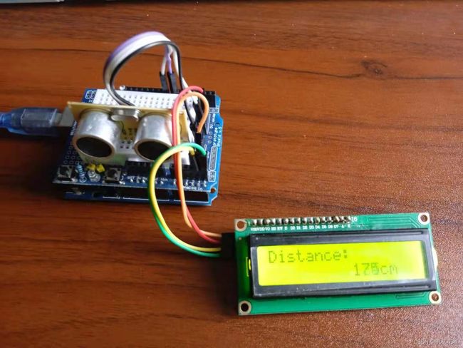
实验场景图
【Arduino】168种传感器模块系列实验(资料代码+仿真编程+图形编程)
实验八十八: LCD1602A液晶屏5V显示模块(IIC/I2C接口)
项目二十二:LCD1602显示超声波测距(单位cm)
实验接线:Uno D7接HC-SR04模块TRIG,D8接ECHO
Arduino------LCD1602
5V-------------VCC
GND-----------GND
A4-----------SDA IIC 数据线
A5-----------SCL IIC 时钟线
实验开源代码
/*
【Arduino】168种传感器模块系列实验(资料代码+仿真编程+图形编程)
实验八十八: LCD1602A液晶屏5V显示模块(IIC/I2C接口)
项目二十二:LCD1602显示超声波测距(单位cm)
实验接线:Uno D7接HC-SR04模块TRIG,D8接ECHO
Arduino------LCD1602
5V-------------VCC
GND-----------GND
A4-----------SDA IIC 数据线
A5-----------SCL IIC 时钟线
*/
#include
#include
#include
LiquidCrystal_I2C lcd(0x27, 16, 2); //0x27 0x3F
#define TRIGGER_PIN 7 // Arduino 引脚连接到超声波传感器上的触发引脚
#define ECHO_PIN 8 // Arduino 引脚连接到超声波传感器上的回声引脚
#define MAX_DISTANCE 400 // 我们想要 ping 的最大距离(以厘米为单位)。 最大传感器距离为 400-500cm
NewPing sonar(TRIGGER_PIN, ECHO_PIN, MAX_DISTANCE); // 引脚和最大距离的新 Ping 设置
void setup() {
Serial.begin(115200); // 以 115200 波特打开串行监视器以查看 ping 结果
lcd.init();
lcd.backlight();
}
void loop() {
delay(100); // 在两次 ping 之间等待 50 毫秒(大约 20 次 ping/秒)。 29ms 应该是两次 ping 之间的最短延迟。
unsigned int uS = sonar.ping(); // 发送 ping,以微秒 (uS) 为单位获取 ping 时间
Serial.print("Ping: ");
Serial.print(uS / US_ROUNDTRIP_CM); // 将 ping 时间转换为以厘米为单位的距离并打印结果(0 = 超出设定的距离范围)
Serial.println("cm");
lcd.setCursor(0, 0);
lcd.print("Distance:");
lcd.setCursor(0, 1);
lcd.print(" ");
lcd.setCursor(9, 1);
lcd.print(uS / US_ROUNDTRIP_CM);
lcd.setCursor(12, 1);
lcd.print("cm");
}
Arduino实验场景图