【雕爷学编程】Arduino动手做(198)---INMP441全向麦克风模块

37款传感器与模块的提法,在网络上广泛流传,其实Arduino能够兼容的传感器模块肯定是不止37种的。鉴于本人手头积累了一些传感器和执行器模块,依照实践出真知(一定要动手做)的理念,以学习和交流为目的,这里准备逐一动手试试多做实验,不管成功与否,都会记录下来——小小的进步或是搞不掂的问题,希望能够抛砖引玉。

**【Arduino】168种传感器模块系列实验(资料代码+仿真编程+图形编程)
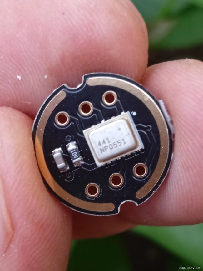
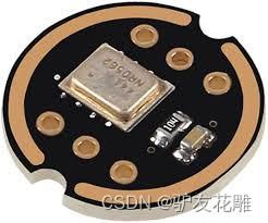
实验一百九十八:INMP441全向麦克风模块 I2S接口 MEMS 高精度 低功耗 支持ESP32
【雕爷学编程】Arduino动手做(198)---INMP441全向麦克风模块_第1张图片
【雕爷学编程】Arduino动手做(198)---INMP441全向麦克风模块_第2张图片
知识点:INMP441
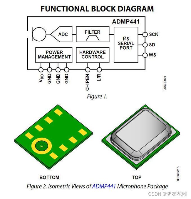
是InvenSense公司推出的一款具有底部端口的高信噪比、低功耗、数字输出的全向MEMS麦克风,信噪比高达61dB,使其成为近场应用的绝佳选择。INMP441的电路结构如图所示,包括MEMS声音传感器、模数转换器(ADC)、抗混叠滤波器、电源管理模块以及行业标准的24位I2S接口。 I2S接口让INMP441可以直接连接到FPGA等数字处理器,而无需再外接音频编解码器。

【雕爷学编程】Arduino动手做(198)---INMP441全向麦克风模块_第3张图片

INMP441是一款高性能,低功耗,数字输出,带底部端口的全向MEMS麦克风。该完整的INMP441解决方案由一个MEMS传感器,信号组成调节,模数转换器,抗混叠滤波器,电源管理和行业标准的24位I²S接口。I²S接口允许INMP441直接连接到数字处理器,如DSP和微控制器,无需使用用于系统中的音频编解码器。INMP441具有高信噪比,是一款出色的选择近场应用。 INMP441具有扁平宽带频率响应,导致自然声音高清晰度。

相关技术资料:https://www.findic.tw/doc/browser/bLXpO7wgL?doc_id=8712428#locale=zh-TW

【雕爷学编程】Arduino动手做(198)---INMP441全向麦克风模块_第4张图片

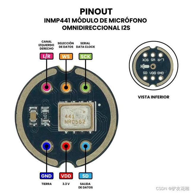
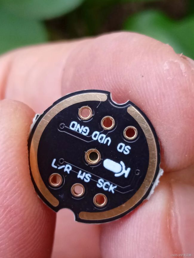
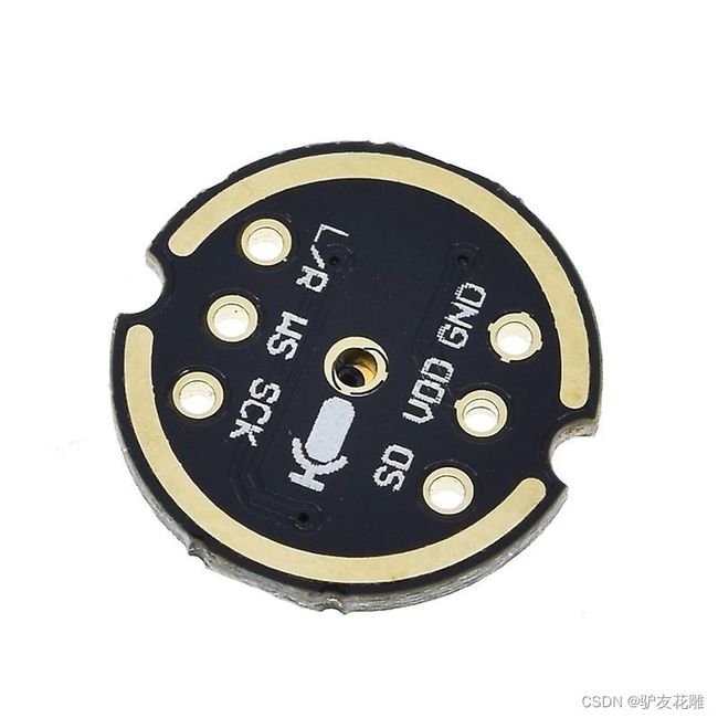
接口定义:
SCK:I²S接口的串行数据时钟
WS :用于I²S接口的串行数据字选择
L/R:左/右声道选择。
设置为低电平时,麦克风在I²S帧的左声道输出信号。
设置为高电平时,麦克风在右声道输出信号
SD:I²S接口的串行数据输出。
VCC:输入电源,1.8V至3.3V.
GND:电源地
【雕爷学编程】Arduino动手做(198)---INMP441全向麦克风模块_第5张图片
I2S(Inter—IC Sound)总线
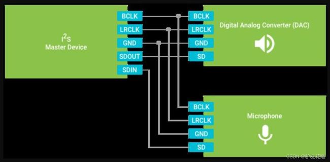
又称集成电路内置音频总线,是飞利浦公司为数字音频设备之间的音频数据传输而制定的一种总线标准。I2S采用了独立的导线传输时钟与数据信号的设计,通过将数据和时钟信号分离,避免了因时差诱发的失真,为用户节省了购买抵抗音频抖动的专业设备的费用。标准的I2S总线电缆是由3根串行导线组成的:1根是时分多路复用(简称TDM)数据线;1根是字选择线;1根是时钟线。音响数据的采集、处理和传输是多媒体技术的重要组成部分。众多的数字音频系统已经进入消费市场,例如数字音频录音带、数字声音处理器。对于设备和生产厂家来说,标准化的信息传输结构可以提高系统的适应性。I2S(Inter—IC Sound)总线是飞利浦公司为数字音频设备之间的音频数据传输而制定的一种总线标准,该总线专责于音频设备之间的数据传输,广泛应用于各种多媒体系统。它采用了沿独立的导线传输时钟与数据信号的设计,通过将数据和时钟信号分离,避免了因时差诱发的失真,为用户节省了购买抵抗音频抖动的专业设备的费用。如图所示就是个同时连接音频输入设备和音频输出设备的I2S接线法。
【雕爷学编程】Arduino动手做(198)---INMP441全向麦克风模块_第6张图片
I2S总线引脚分别是:
BCLK - 位时钟(Bit Clock),由I2S Master Device(I2S主设备)产生,也称为SCLK。对应数字音频的每一位数据,SCLK都有1个脉冲。BCLK的频率 = 2 × 采样频率 × 采样位数
LRCLK - 左右声道选择时钟,LRCK的频率等于采样频率,它输出低电平时,SDOUT和SDIN的数据都为左声道数据,它输出高电平时,SDIN和SDIN的数据都为右声道数据。也称为FS(Frame Select)或WS(Word Select)
GND - 公共接地,为主从设备提供低电平参考
SDOUT - 为PCM数据输出
SDIN - 为PCM数据输入
MCLK - 在某些比较低级的系统中,主设备还提供从设备的执行时钟以确保更好的数据同步,通常为成为主时钟(Master Clock)或系统时钟(System Clock)。它的频率通常是采样频率的256倍或384倍

如果你只需要音频输入或者只需要音频输出,直接少接SDOUT或SDIN就好了。另外输入和输出都共用BCLK时钟线和LRCLK时钟线,所以主时钟由I2S Master Device(I2S主设备)产生就好了。
【雕爷学编程】Arduino动手做(198)---INMP441全向麦克风模块_第7张图片
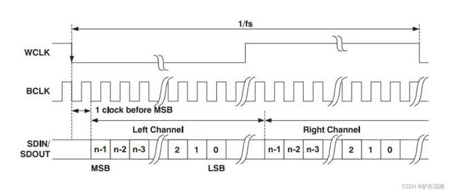
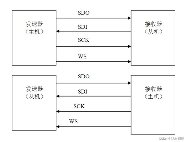
I2S格式的信号无论有多少位有效数据,数据的最高位总是出现在LRCK变化(也就是一帧开始)后的第2个SCLK脉冲处。这就使得接收端与发送端的有效位数可以不同。如果接收端能处理的有效位数少于发送端,可以放弃数据帧中多余的低位数据;如果接收端能处理的有效位数多于发送端,可以自行补足剩余的位。这种同步机制使得数字音频设备的互连更加方便,而且不会造成数据错位。随着技术的发展,在统一的 I2S接口下,出现了多种不同的数据格式。根据SDATA数据相对于LRCK和SCLK的位置不同,分为左对齐(较少使用)、I2S格式(即飞利浦规定的格式)和右对齐(也叫日本格式、普通格式)。

I2S有3个主要信号
1.串行时钟SCLK,也叫位时钟(BCLK),即对应数字音频的每一位数据,SCLK都有1个脉冲。SCLK的频率=2×采样频率×采样位数。
2. 帧时钟LRCK,(也称WS),用于切换左右声道的数据。LRCK为“1”表示正在传输的是右声道的数据,为“0”则表示正在传输的是左声道的数据。LRCK的频率等于采样频率。
3.串行数据SDATA,就是用二进制补码表示的音频数据。
有时为了使系统间能够更好地同步,还需要另外传输一个信号MCLK,称为主时钟,也叫系统时钟(Sys Clock),是采样频率的256倍或384倍。

【雕爷学编程】Arduino动手做(198)---INMP441全向麦克风模块_第8张图片

.
INMP441麦克风模块的主要组件包括全向麦克风MEMS(微机电系统)INMP441,其特点是尺寸紧凑,高性能,低功耗和数字输出,该麦克风在其包装中包含信号调理器,模数转换器,抗混叠滤波器等功能。

INMP441 麦克风模块的主接口是一个 2 位 I24S(IC 间声音)接口,这允许用户将麦克风直接连接到数字处理器,例如 ESP 32 或其他具有协议支持的微控制器或开发板,而无需在系统中安装音频编解码器。

由于高性能、高信噪比和其他功能,您可以在录音、音频处理器、vumeter、电子设备、安全系统等中使用这款麦克风:

*注意: 由于麦克风通过I2S接口进行通信,因此您应该知道您的微控制器或开发板与此接口兼容。

【雕爷学编程】Arduino动手做(198)---INMP441全向麦克风模块_第9张图片

规格和特点
型号: INMP441
印刷电路板颜色:黑色
方向性:全向
类型: 微机电系统
灵敏度: -29 至 -23 dBFS
信噪比:61 dBA
接口:I2S 数字 24 位
频率响应:
低频:60Hz
高频:15 kHz
电源电压:
最小值:1.62 V
最大:3.63 V
电流消耗:1.4 mA
声压级:最大160dB
工作温度:-40 至 85°C
尺寸: ∅14 毫米
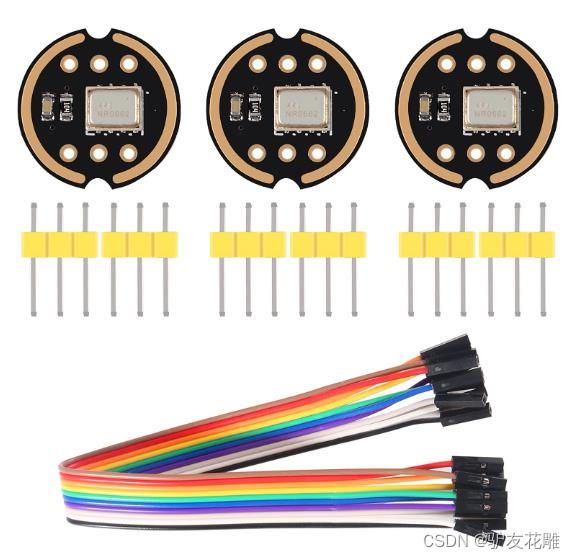
包括:2 针接头公头 3 针 2.5mm 间距

针:

SCK:用于I2S接口的串行数据时钟
WS: 为 I2S 接口选择串行数据字
升/右: 左/右通道选择。当其电平为低电平时,输出信号将位于I2S帧的左侧通道上,当设置为高电平时,输出将在右侧通道上。
接地: 地球。
VDD: 电源电压,最大 3.63V
标清: I2S接口的串行数据输出

【雕爷学编程】Arduino动手做(198)---INMP441全向麦克风模块_第10张图片
【雕爷学编程】Arduino动手做(198)---INMP441全向麦克风模块_第11张图片

/*
 * app_main.c
 *
 *  Created on: 30.03.2017
 *      Author: michaelboeckling
 */

#include 
#include 
#include 
#include 
#include 
#include 
#include 

#include "freertos/FreeRTOS.h"
#include "freertos/task.h"
#include "freertos/event_groups.h"
#include "esp_system.h"
#include "esp_log.h"
#include "driver/i2s.h"

#define TAG "main"

static void init_i2s()
{
	const int sample_rate = 44100;

	/* TX: I2S_NUM_0 */
    i2s_config_t i2s_config_tx = {
	.mode = I2S_MODE_MASTER | I2S_MODE_TX,
	.sample_rate = sample_rate,
	.bits_per_sample = I2S_BITS_PER_SAMPLE_16BIT,
	.channel_format = I2S_CHANNEL_FMT_RIGHT_LEFT,   // 2-channels
	.communication_format = I2S_COMM_FORMAT_I2S_MSB,
	.dma_buf_count = 32,                            // number of buffers, 128 max.
	.dma_buf_len = 32 * 2,                          // size of each buffer
	.intr_alloc_flags = ESP_INTR_FLAG_LEVEL1        // Interrupt level 1
    };

    i2s_pin_config_t pin_config_tx = {
			.bck_io_num = GPIO_NUM_26,
			.ws_io_num = GPIO_NUM_25,
			.data_out_num = GPIO_NUM_22,
			.data_in_num = GPIO_NUM_23
	};
    i2s_driver_install(I2S_NUM_0, &i2s_config_tx, 0, NULL);
    i2s_set_pin(I2S_NUM_0, &pin_config_tx);


    /* RX: I2S_NUM_1 */
    i2s_config_t i2s_config_rx = {
	.mode = I2S_MODE_MASTER | I2S_MODE_RX, // Only TX
	.sample_rate = sample_rate,
	.bits_per_sample = I2S_BITS_PER_SAMPLE_32BIT,    // Only 8-bit DAC support
	.channel_format = I2S_CHANNEL_FMT_RIGHT_LEFT,   // 2-channels
	.communication_format = I2S_COMM_FORMAT_I2S_MSB,
	.dma_buf_count = 32,                            // number of buffers, 128 max.
	.dma_buf_len = 32 * 2,                          // size of each buffer
	.intr_alloc_flags = ESP_INTR_FLAG_LEVEL1        // Interrupt level 1
	};

	i2s_pin_config_t pin_config_rx = {
		.bck_io_num = GPIO_NUM_2,
		.ws_io_num = GPIO_NUM_15,
		.data_out_num = I2S_PIN_NO_CHANGE,
		.data_in_num = GPIO_NUM_13
	};

	i2s_driver_install(I2S_NUM_1, &i2s_config_rx, 0, NULL);
	i2s_set_pin(I2S_NUM_1, &pin_config_rx);

}


void task_megaphone(void *pvParams)
{
	uint16_t buf_len = 1024;
	char *buf = calloc(buf_len, sizeof(char));

	struct timeval tv = {0};
	struct timezone *tz = {0};
	gettimeofday(&tv, &tz);
	uint64_t micros = tv.tv_usec + tv.tv_sec * 1000000;
	uint64_t micros_prev = micros;
	uint64_t delta = 0;

	init_i2s();

	int cnt = 0;
	int bytes_written = 0;

	while(1)
	{
		char *buf_ptr_read = buf;
		char *buf_ptr_write = buf;

		// read whole block of samples
		int bytes_read = 0;
		while(bytes_read == 0) {
			bytes_read = i2s_read_bytes(I2S_NUM_1, buf, buf_len, 0);
		}

		uint32_t samples_read = bytes_read / 2 / (I2S_BITS_PER_SAMPLE_32BIT / 8);

		//  convert 2x 32 bit stereo -> 1 x 16 bit mono
		for(int i = 0; i < samples_read; i++) {

			// const char samp32[4] = {ptr_l[0], ptr_l[1], ptr_r[0], ptr_r[1]};

			// left
			buf_ptr_write[0] = buf_ptr_read[2]; // mid
			buf_ptr_write[1] = buf_ptr_read[3]; // high

			// right
			buf_ptr_write[2] = buf_ptr_write[0]; // mid
			buf_ptr_write[3] = buf_ptr_write[1]; // high


			buf_ptr_write += 2 * (I2S_BITS_PER_SAMPLE_16BIT / 8);
			buf_ptr_read += 2 * (I2S_BITS_PER_SAMPLE_32BIT / 8);
		}

		// local echo
		bytes_written = samples_read * 2 * (I2S_BITS_PER_SAMPLE_16BIT / 8);
		i2s_write_bytes(I2S_NUM_0, buf, bytes_written, portMAX_DELAY);

		cnt += samples_read;

		if(cnt >= 44100) {
			gettimeofday(&tv, &tz);
			micros = tv.tv_usec + tv.tv_sec * 1000000;
			delta = micros - micros_prev;
			micros_prev = micros;
			printf("%d samples in %" PRIu64 " usecs\n", cnt, delta);

			cnt = 0;
		}
	}
}

/**
 * entry point
 */
void app_main()
{
    printf("starting app_main()\n");
    xTaskCreatePinnedToCore(&task_megaphone, "task_megaphone", 16384, NULL, 20, NULL, 0);
}

【雕爷学编程】Arduino动手做(198)---INMP441全向麦克风模块_第12张图片

#include 
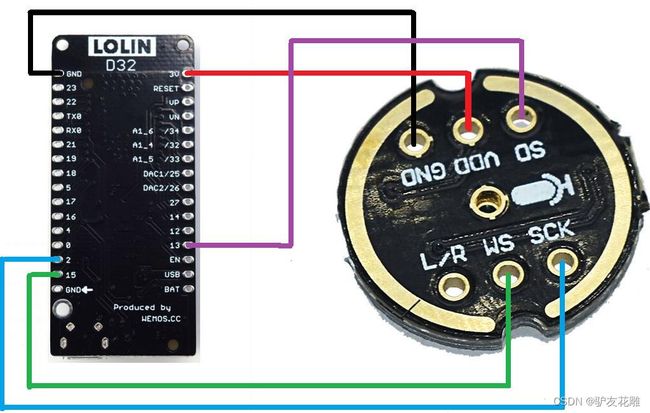
#define I2S_WS 15
#define I2S_SD 13
#define I2S_SCK 2

#define I2S_PORT I2S_NUM_0

void setup() {
  Serial.begin(115200);
  Serial.println("Setup I2S ...");

  delay(1000);
  i2s_install();
  i2s_setpin();
  i2s_start(I2S_PORT);
  delay(500);
}

void loop() {
  int32_t sample = 0;
  int bytes = i2s_pop_sample(I2S_PORT, (char*)&sample, portMAX_DELAY);
  if(bytes > 0){
    Serial.println(sample);
  }
}

void i2s_install(){
  const i2s_config_t i2s_config = {
    .mode = i2s_mode_t(I2S_MODE_MASTER | I2S_MODE_RX),
    .sample_rate = 44100,
    .bits_per_sample = i2s_bits_per_sample_t(32),
    .channel_format = I2S_CHANNEL_FMT_RIGHT_LEFT,
    .communication_format = i2s_comm_format_t(I2S_COMM_FORMAT_I2S | I2S_COMM_FORMAT_I2S_MSB),
    .intr_alloc_flags = 0, // default interrupt priority
    .dma_buf_count = 8,
    .dma_buf_len = 64,
    .use_apll = false
  };

  i2s_driver_install(I2S_PORT, &i2s_config, 0, NULL);
}

void i2s_setpin(){
  const i2s_pin_config_t pin_config = {
    .bck_io_num = I2S_SCK,
    .ws_io_num = I2S_WS,
    .data_out_num = -1,
    .data_in_num = I2S_SD
  };

  i2s_set_pin(I2S_PORT, &pin_config);
}

【雕爷学编程】Arduino动手做(198)---INMP441全向麦克风模块_第13张图片

/*
  ESP32 I2S Ejemplo de uso del micrófono
  Muestrea sonido con el micrófono y lo despliega en el graficador serial
  Requiere un Micrófono INMP441
*/

// Incluir el driver I2S
#include 
// Conexiones al INMP441
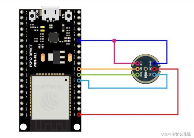
#define I2S_WS 25
#define I2S_SD 32
#define I2S_SCK 33
// Uso del procesador 0 I2S
#define I2S_PORT I2S_NUM_0

// Define la longitud del buffer de entrada
#define bufferLen 64
int16_t sBuffer[bufferLen];

void i2s_install() {
  // Configuración del I2S
  const i2s_config_t i2s_config = {
    .mode = i2s_mode_t(I2S_MODE_MASTER | I2S_MODE_RX),
    .sample_rate = 44100,
    .bits_per_sample = i2s_bits_per_sample_t(16),
    .channel_format = I2S_CHANNEL_FMT_ONLY_LEFT,
    .communication_format = i2s_comm_format_t(I2S_COMM_FORMAT_I2S | I2S_COMM_FORMAT_I2S_MSB),
    .intr_alloc_flags = 0,
    .dma_buf_count = 8,
    .dma_buf_len = bufferLen,
    .use_apll = false
  };

  i2s_driver_install(I2S_PORT, &i2s_config, 0, NULL);
}

void i2s_setpin() {
  // Configuración de los pines I2S
  const i2s_pin_config_t pin_config = {
    .bck_io_num = I2S_SCK,
    .ws_io_num = I2S_WS,
    .data_out_num = -1,
    .data_in_num = I2S_SD
  };

  i2s_set_pin(I2S_PORT, &pin_config);
}

void setup() {

  // Configuración del monitor serial
  Serial.begin(115200);
  Serial.println(" ");

  delay(1000);

  // Inicialización del I2S
  i2s_install();
  i2s_setpin();
  i2s_start(I2S_PORT);


  delay(500);
}

void loop() {

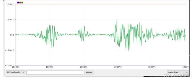
  // Impresión de valores falsos para "bloquear el rango" en el graficador serial
  // Cambiar el valor de rangelimit para modificar la resolución de la gráfica
  int rangelimit = 3000;
  Serial.print(rangelimit * -1);
  Serial.print(" ");
  Serial.print(rangelimit);
  Serial.print(" ");

  // Obtención de los datos I2S y moverlos al buffer de datos
  size_t bytesIn = 0;
  esp_err_t result = i2s_read(I2S_PORT, &sBuffer, bufferLen, &bytesIn, portMAX_DELAY);

  if (result == ESP_OK)
  {
    // Lectura del buffer de datos I2S
    int16_t muestras = bytesIn / 8;
    if (muestras > 0) {
      float promedio = 0;
      for (int16_t i = 0; i < muestras; ++i) {
        promedio += (sBuffer[i]);
      }

      // Promedio de los datos leídos
      promedio /= muestras;

      // Gráfica de los datos obtenidos
      Serial.println(promedio);
    }
  }
}

【雕爷学编程】Arduino动手做(198)---INMP441全向麦克风模块_第14张图片

你可能感兴趣的:(单片机,嵌入式硬件,c++,Arduino,物联网,INMP441全向麦克风模块,ESP32)