Python 代码一键转流程图---python=>flowchart-dsl=>流程图
简介:
这个项目是基于大名鼎鼎的 flowchart.js。
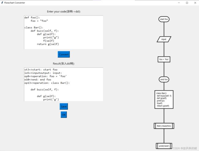
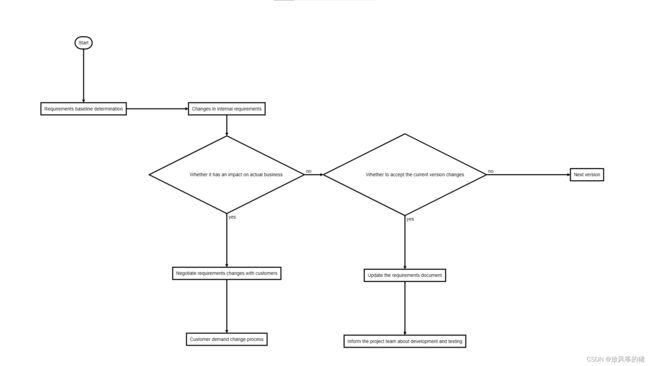
下面贴几张运行图片:
如果直接输入dsl代码,再进行转化就可以很好的画出流程图
flowchart.js
如果你使用 Typora,可能知道在 Typora 中用 flow 可以用一种简单的文本语言来写流程图,根据 Typora 的文档,这个功能来自开源的 flowchart.js。
我的方案就是把 Python 代码转化成这种 flowchart 语言,然后你就可以借助 flowchart.js.org、Typora、 francoislaberge/diagrams 等等工具来生成流程图了。
st=>start: Start:>http://www.google.com[blank]
e=>end:>http://www.google.com
op1=>operation: My Operation
sub1=>subroutine: My Subroutine
cond=>condition: Yes
or No?:>http://www.google.com
io=>inputoutput: catch something...
para=>parallel: parallel tasks

st->op1->cond
cond(yes)->io->e
cond(no)->para
para(path1, bottom)->sub1(right)->op1
para(path2, top)->op1
PyFlowchart
下面简要介绍如何使用我实现的 PyFlowchart,更详细的说明请看项目的 README。
安装 PyFlowchart:
$ pip3 install pyflowchart
写一个 simple.py 文件:
def foo(a, b):
    if a:
        print("a")
    else:
        for i in range(3):
            print("b")
    return a + b
运行 PyFlowchart:
$ python3 -m pyflowchart simple.py
它会输出 flowchart 代码:
st4439920016=>start: start foo
io4439920208=>inputoutput: input: a, b
cond4439920592=>condition: if a
sub4439974736=>subroutine: print('a')
io4439974672=>inputoutput: output:  (a + b)
e4439974352=>end: end function return
cond4439974224=>operation: print('b') while  i in range(3)

st4439920016->io4439920208
io4439920208->cond4439920592
cond4439920592(yes)->sub4439974736
sub4439974736->io4439974672
io4439974672->e4439974352
cond4439920592(no)->cond4439974224
cond4439974224->io4439974672
访问 flowchart.js.org,把上面生成的代码粘贴到文本框里,右边就会自动生成流程图了:
当然,你也可以直接把这些代码放到 Typora 的 flow 代码块里,也会自动生成流程图。如果你喜欢使用命令行,也可以用 francoislaberge/diagrams 来生成流程图。
如果生成的流程图有让人不满意的地方(比如,线条重叠)或者你喜欢指定样式,参考 flowchart.js.org,手动修改一下生成的 flowchart 就可以了,非常方便。
实现原理
1. 得到 flowchart - DSL
PyFlowchart 利用 Python 内置的 ast包,把代码转化成 AST(抽象语法树),然后把 AST 转化成自己定义的 Node 组成的图,每个 Node 对应一个 flowchart 中的 node,遍历这个图就可以得到流程图了。
关于 ast 包,可以看看这篇文章:AST 模块:用 Python 修改 Python 代码,虽然很老,但十分简单易懂。总而言之,利用 ast 包,我们可以把一段 Python 代码转化为一个数据结构:
>>> import ast
>>> expr = """
... def add(a, b):
...     return a + b
... """
>>> expr_ast = ast.parse(expr)
>>> expr_ast
<_ast.Module object at 0x10c773e10>
>>> ast.dump(expr_ast)
# p.s. 这里手动做了格式化
Module(body=[FunctionDef(name='add',
  args=arguments(
    args=[
      arg(arg='a', annotation=None),
      arg(arg='b', annotation=None)],
    vararg=None, kwonlyargs=[], kw_defaults=[], kwarg=None, defaults=[]),
  body=[Return(value=BinOp(
    left=Name(id='a', ctx=Load()),
    op=Add(),
    right=Name(id='b', ctx=Load())))],
  decorator_list=[],
  returns=None)])
学会了这个东西,接下来的工作就是把这个 expr_ast (_ast.Module 对象) 翻译成流程图了。我们用面向对象来的方法来实现:
![]()
Node 是最最基础的类,表示流程图中的一个节点,其他一切都继承自它。Node 有节点类型、名称、内容等属性,提供的 fc_definition()、fc_connection() 方法可以把自己转化为 flowchart 语言的字符串。另外的 __visited 和 _traverse() 是用来遍历图的。与 flowchart 中的 node types 对应,我们实现了各种 Node 的子类:StartNode、EndNode、OperationNode…
NodesGroup 是一个特殊的 Node,它自己不会出现在生成的 flowchart 中,但它可以包含一些其他 Node。这个设计是受到 Android 的 View、ViewGroup 的启发,有了这个 NodesGroup,if 语句、for / while 循环这样有嵌套的 body 的情况就很容易处理了。
AstNode 表示一个从 AST 对象得到的 Node。构造 AstNode,就是把某个 AST 对象翻译成一个 Node(也可以是 NodesGroup)。其子类就和各种 ast 对象对应(也就和 Python 的各种语句对应): If、Loop、Return …
Flowchart 代表一张流程图。流程图就是一堆连在一起的节点嘛,所以 Flowchart 是 NodesGroup 的子类。在其 from_code() 中方法中,实现了用 ast 包解析 Python 代码,得到 ast 对象的工作。在 flowchart() 方法中,遍历图,拿到所有节点的 flowchart 表示,汇总成一张完整的 flowchart 流程图。
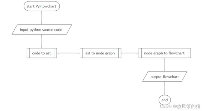
其实这个东西很简单,更具体的实现看源码就很好理解了,在此不做赘述。总结一下:
Flowchart 中利用 ast 包实现了 code to ast;
AstNode 及其子类实现了 ast to node graph;
Node 及其子类实现了 node graph to flowchart。
2. 通过Diagrams转化为流程图
我这里使用了Diagrams将flowchart转化为流程图
diagrams需要使用下面的命令下载,这样下载的diagrams是全局的,需要先下载node。
npm install -g diagrams下载好后在项目文件夹下执行下面的命令即可生成流程图
diagrams flowchart input.flowchart flowchart.svg
3. 界面显示
思路:
- 有两个输入框,一个输入python代码,一个输入dsl代码,输入python点击转化可以生成dsl代码,也可以手动输入dsl代码;
- 得到dsl代码后点击ok按钮,调用Diagrams将dsl代码转化为流程图,此时得到的流程图是svg格式的;
- 在调用graphviz将svg格式的图片转化为png格式显示在窗口中。
关于graphviz的详细解释可以看:Python生成决策树的.dot文件以及使用graphviz将其转化为png等图片格式
下面是一部分代码:
Diagrams.py
import os
import tkinter as tk
from tkinter import filedialog

#选择保存路径
root = tk.Tk()
root.withdraw()
file_path = filedialog.asksaveasfilename(defaultextension=".svg")

#保存 SVG 文件
os.system(f"diagrams flowchart simple.flowchart {file_path}")

#将 SVG 文件转换为 PNG 格式
png_path = os.path.splitext(file_path)[0] + ".png"
os.system(f"cairosvg {file_path} -o {png_path}")

#打开 PNG 文件
os.startfile(png_path)
GUI.py
    def convert(self):
        code = self.textbox.get("1.0", "end-1c")
        chart = Flowchart.from_code(code)

        self.result_textbox.delete("1.0", "end")
        self.result_textbox.insert("1.0", chart.flowchart())

        # 保存流程图到文件
        with open("input.flowchart", "w") as f:
            f.write(chart.flowchart())

    def save(self):
        # 获取文本框内容
        content = self.result_textbox.get("1.0", "end-1c")
        # 将内容保存到文件
        with open("input.flowchart", "w") as f:
            f.write(content)

    def ok(self):
        # 选择保存路径
        root = tk.Tk()
        root.withdraw()
        file_path = filedialog.asksaveasfilename(defaultextension=".svg")

        # 保存 SVG 文件
        os.system(f"diagrams flowchart simple.flowchart {file_path}")

        # 将 SVG 文件转换为 PNG 格式
        png_path = os.path.splitext(file_path)[0] + ".png"
        os.system(f"cairosvg {file_path} -o {png_path}")

        # 打开 PNG 文件
        # os.startfile(png_path)
        # 显示图片
        self.show_image(png_path)

    def show_image(self, png_path):
        # 打开图片
        img = Image.open(png_path)

        # 调整图片大小
        width, height = img.size
        if width > height:
            new_width = 1000
            new_height = int(height * (new_width / width))
        else:
            new_height = 800
            new_width = int(width * (new_height / height))
        img = img.resize((new_width, new_height))

        # 将图片显示到标签中
        self.image = ImageTk.PhotoImage(img)
        self.image_label.config(image=self.image)
        self.image_label.image = self.image
参考文章:
Python 代码一键转流程图_python代码转流程图_CDFMLR的博客-CSDN博客
Python生成决策树的.dot文件以及使用graphviz将其转化为png等图片格式(附本人自己编写的具体函数源码)_ななみ けんと的博客-CSDN博客
seflless/diagrams: Generate Flowcharts, Network Sequence Diagrams, GraphViz Dot Diagrams, and Railroad Diagrams (github.com)


