计算机图形学线性代数相关概念
Transformation(2D-Model)
Scale(缩放)
[ x ′ y ′ ] = [ s 0 0 s ] [ x y ] (等比例缩放) \left[ \begin{matrix} x' \\ y' \end{matrix} \right]= \left[ \begin{matrix} s & 0 \\ 0 & s \end{matrix} \right] \left[ \begin{matrix} x \\ y \end{matrix} \right] \tag{等比例缩放} [x′y′]=[s00s][xy](等比例缩放)
[ x ′ y ′ ] = [ s x 0 0 s y ] [ x y ] (x,y不同比例缩放) \left[ \begin{matrix} x' \\ y' \end{matrix} \right] =\left[ \begin{matrix} s_x & 0 \\ 0 & s_y \end{matrix} \right] \left[ \begin{matrix} x \\ y \end{matrix} \right] \tag{x,y不同比例缩放} [x′y′]=[sx00sy][xy](x,y不同比例缩放)
Reflection(反转)
[ x ′ y ′ ] = [ − 1 0 0 1 ] [ x y ] (沿y轴对称反转) \left[ \begin{matrix} x' \\ y' \end{matrix} \right] =\left[ \begin{matrix} -1 & 0 \\ 0 & 1 \end{matrix} \right] \left[ \begin{matrix} x \\ y \end{matrix} \right] \tag{沿y轴对称反转} [x′y′]=[−1001][xy](沿y轴对称反转)
沿x轴或原点对称同理
Shear(切变)
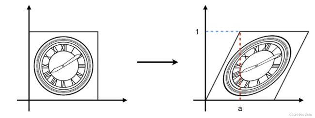
如下图,切变的跨度(
a)和y是成正比例的。坐标归一化后,也就是x每次加一个y倍的a
[ x ′ y ′ ] = [ 1 a 0 1 ] [ x y ] (坐标归一化后的操作) \left[ \begin{matrix} x' \\ y' \end{matrix} \right] =\left[ \begin{matrix} 1 & a \\ 0 & 1 \end{matrix} \right] \left[ \begin{matrix} x \\ y \end{matrix} \right] \tag{坐标归一化后的操作} [x′y′]=[10a1][xy](坐标归一化后的操作)
Rotate(旋转)
R θ = [ c o s θ − s i n θ s i n θ c o s θ ] R_\theta =\left[ \begin{matrix} cos\theta & -sin\theta \\ sin\theta & cos\theta \end{matrix} \right] Rθ=[cosθsinθ−sinθcosθ]
Homogenous coordinates(齐次坐标)
为什么引入齐次坐标?
区分向量和点,更易于表示仿射变换仿射变换就是线性的几何变换加上一个平移,包括旋转、缩放、平移、切变。
齐次坐标的意义就是让平移变换和其它线性变换一样,都能表述成一个矩阵相乘的形式!
具体做法:
Add a third coordinate (w-coordinate)
- 2D point = ( x , y , 1 ) T (x,y,1)^T (x,y,1)T
- 2D vector = ( x , y , 0 ) T (x,y,0)^T (x,y,0)T
向量具有平移不变性,只表示方向和大小!
运算过程中 w 分量的值:
- vector + vector = vector 向量+向量结果依旧为向量,w此时仍为0
- point - point = vector 点-点结果为向量,w此时为0
- point + vector = point 点+向量结果为点,w此时为1
- point + point = ?? 点+点 无意义? ,w此时为2
- 扩充意义:点 + 点 = 两个点的中点
w ! = 0 , [ x y w ] = [ x / w y / w w / w ] = [ x / w y / w 1 ] w != 0, \left[ \begin{matrix} x \\ y \\ w \end{matrix} \right] = \left[ \begin{matrix} x/w \\ y/w \\ w/w \end{matrix} \right] =\left[ \begin{matrix} x/w \\ y/w \\ 1 \end{matrix} \right] w!=0, xyw = x/wy/ww/w = x/wy/w1
Translation(平移)
translation is NOT linear transform!
平移不是线性变换,线性变换的对象是向量,向量是不存在空间位置的!平移是对点进行操作。
[ x ′ y ′ w ′ ] = [ 1 0 t x 0 1 t y 0 0 1 ] [ x y w ] = [ x + t x y + t y w ] (向量的w为0,点的w为1) \left[ \begin{matrix} x' \\ y' \\ w' \end{matrix} \right] =\left[ \begin{matrix} 1 & 0 & t_x \\ 0 & 1 & t_y \\ 0 & 0 & 1 \end{matrix} \right] \left[ \begin{matrix} x \\ y \\ w \end{matrix} \right] = \left[ \begin{matrix} x + t_x \\ y + t_y \\ w \end{matrix} \right] \tag{向量的w为0,点的w为1} x′y′w′ = 100010txty1 xyw = x+txy+tyw (向量的w为0,点的w为1)
引入齐次坐标后的变换矩阵
Scale
S ( s x , s y ) = [ s x 0 0 0 s y 0 0 0 1 ] S(s_x, s_y) =\left[ \begin{matrix} s_x & 0 & 0 \\ 0 & s_y & 0 \\ 0 & 0 & 1 \end{matrix} \right] S(sx,sy)= sx000sy0001
Rotation
R θ = [ c o s θ − s i n θ 0 s i n θ c o s θ 0 0 0 1 ] R_\theta =\left[ \begin{matrix} cos\theta & -sin\theta & 0\\ sin\theta & cos\theta & 0 \\ 0 & 0 & 1 \end{matrix} \right] Rθ= cosθsinθ0−sinθcosθ0001
Translation
T ( t x , t y ) = [ 1 0 t x 0 1 t y 0 0 1 ] T(t_x, t_y)= \left[ \begin{matrix} 1 & 0 & t_x \\ 0 & 1 & t_y \\ 0 & 0 & 1 \end{matrix} \right] T(tx,ty)= 100010txty1
Other
逆变换
执行一个操作,再执行这个操作的逆操作,相当于不变。
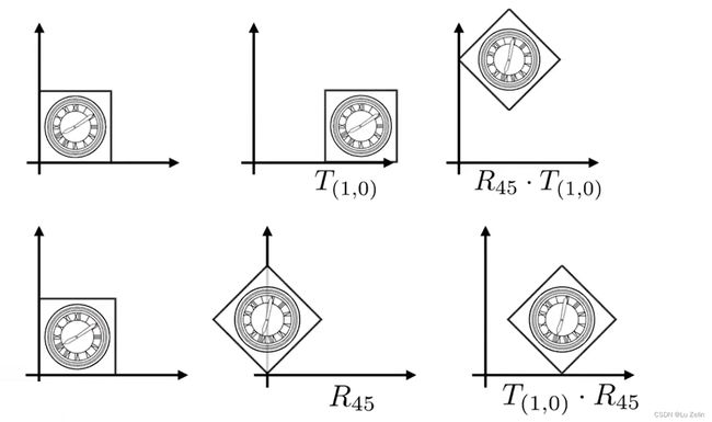
变换顺序
根据矩阵的分配率性质,多个操作可以合并成一个矩阵。
变换组合到一个矩阵时,先进行线性变换,再进行平移。
[ x ′ y ′ 1 ] = [ a b t x c d t y 0 0 1 ] [ x y 1 ] \left[ \begin{matrix} x' \\ y' \\ 1 \end{matrix} \right] = \left[ \begin{matrix} a & b & t_x \\ c & d & t_y \\ 0 & 0 & 1 \end{matrix} \right] \left[ \begin{matrix} x \\ y \\ 1 \end{matrix} \right] x′y′1 = ac0bd0txty1 xy1
变换的分解
Q:如何围绕给定点进行旋转(非原点)?
A:1.平移到原点 2.旋转 3.反向平移复位
Transformation(3D-Model)
Use homogeneous coordinates again:
- 3D point = ( x , y , z , 1 ) T (x,y,z,1)^T (x,y,z,1)T
- 3D vector = ( x , y , z , 0 ) T (x,y,z,0)^T (x,y,z,0)T
w 分量不为0时的扩充意义:
w ! = 0 , [ x y z w ] = [ x / w y / w z / w w / w ] = [ x / w y / w z / w 1 ] w != 0, \left[ \begin{matrix} x \\ y \\ z \\ w \end{matrix} \right]=\left[ \begin{matrix} x/w \\ y/w \\ z/w \\ w/w \end{matrix} \right] =\left[ \begin{matrix} x/w \\ y/w \\ z/w \\ 1 \end{matrix} \right] w!=0, xyzw = x/wy/wz/ww/w = x/wy/wz/w1
Use 4x4 matrices for affine(仿射) transformations
[ x ′ y ′ z ′ 1 ] = [ a b c t x d e f t y g h i t z 0 0 0 1 ] [ x y z 1 ] \left[ \begin{matrix} x' \\ y' \\ z' \\ 1 \end{matrix} \right] =\left[ \begin{matrix} a & b & c & t_x \\ d & e & f & t_y \\ g & h & i & t_z \\ 0 & 0 & 0 & 1 \end{matrix} \right] \left[ \begin{matrix} x \\ y \\ z \\ 1 \end{matrix} \right] x′y′z′1 = adg0beh0cfi0txtytz1 xyz1
先进行线性变换,再进行平移。
Rotation around x,y or z-axis沿着标准轴旋转
R x ( α ) = [ 1 0 0 0 0 c o s α − s i n α 0 0 s i n α c o s α 0 0 0 0 1 ] − − − − − − − − − − − − − − − − − − − − − − − − − R y ( α ) = [ c o s α 0 s i n α 0 0 1 0 0 − s i n α 0 c o s α 0 0 0 0 1 ] − − − − − − − − − − − − − − − − − − − − − − − − − R z ( α ) = [ c o s α − s i n α 0 0 s i n α c o s α 0 0 0 0 1 0 0 0 0 1 ] R_x(\alpha) =\left[ \begin{matrix} 1 & 0 & 0 & 0 \\ 0 & cos\alpha & -sin\alpha & 0 \\ 0 & sin\alpha & cos\alpha & 0 \\ 0 & 0 & 0 & 1 \\ \end{matrix} \right] \\ \\ ------------------------- \\ R_y(\alpha) =\left[ \begin{matrix} cos\alpha & 0 & sin\alpha & 0 \\ 0 & 1 & 0 & 0 \\ -sin\alpha & 0 & cos\alpha & 0 \\ 0 & 0 & 0 & 1 \\ \end{matrix} \right] \\ \\ ------------------------- \\ R_z(\alpha) =\left[ \begin{matrix} cos\alpha & -sin\alpha & 0 & 0 \\ sin\alpha & cos\alpha & 0 & 0 \\ 0 & 0 & 1 & 0 \\ 0 & 0 & 0 & 1 \\ \end{matrix} \right] Rx(α)= 10000cosαsinα00−sinαcosα00001 −−−−−−−−−−−−−−−−−−−−−−−−−Ry(α)= cosα0−sinα00100sinα0cosα00001 −−−−−−−−−−−−−−−−−−−−−−−−−Rz(α)= cosαsinα00−sinαcosα0000100001
Compose any 3D rotation from Rx,Ry, Rz沿着任意轴旋转
如图,α β γ分别对应roll pitch yaw(欧拉角)。
- Roll:翻滚,我们以圣地安列斯里最恶心的开飞机为例,Roll将你的飞机机头朝向不变,进行机身的转动,机翼从水平到竖直这种。
- Pitch:是将你的飞机机头向上抬或者向下降,范围在-90 ~ 90 .
- Yaw:是水平方向上转动机头的朝向,范围在0~360。
图形学中有一个办法,可以把任意的一个旋转分解再X,Y,Z三轴上,分别做旋转从而得到了一个公式,也就是罗德里德斯旋转公式:
罗德里德斯旋转公式给了我们一个旋转矩阵,它定义了一个旋转轴 n 和一个旋转角度 α。
我们默认旋转轴 n 是过原点的,也就是起点在原点上,方向是n这个方向,旋转角度为α。
如果想要沿着任意轴旋转,但该轴起点不是原点,则需要先将所有的物体都进行平移是的旋转轴的起点为原点,然后进行旋转,最后再平移回去。
矩阵N是两个向量叉乘写成矩阵形式。
Transformation(View/Camera)
前置概念Ⅰ:旋转矩阵的逆矩阵等于它的转置矩阵
R θ = [ c o s θ − s i n θ s i n θ c o s θ ] − − − − − − − − − − − − − R − θ = [ c o s θ s i n θ − s i n θ c o s θ ] ★ R − θ = R θ − 1 = R θ T R_\theta = \left[ \begin{matrix} cos\theta & -sin\theta\\ sin\theta & cos\theta \\ \end{matrix} \right] \\ \\ ------------- \\ R_{-\theta} = \left[ \begin{matrix} cos\theta & sin\theta\\ -sin\theta & cos\theta \\ \end{matrix} \right] \\ \\ ★ R_{-\theta}=R_{\theta}^{-1}=R_{\theta}^T Rθ=[cosθsinθ−sinθcosθ]−−−−−−−−−−−−−R−θ=[cosθ−sinθsinθcosθ]★R−θ=Rθ−1=RθT
如上公式,从矩阵中我们可以发现 R − θ = R θ T R_{-\theta}=R_{\theta}^T R−θ=RθT而在图形学中我们知道 R θ R_{\theta} Rθ 和 R − θ R_{-\theta} R−θ 是一个互逆的操作
因此 R − θ = R θ − 1 = R θ T R_{-\theta}=R_{\theta}^{-1}=R_{\theta}^T R−θ=Rθ−1=RθT
因此我们可以得出 旋转矩阵的逆等于它的转置矩阵 这一定义,之后的内容我们会用到这个性质。
在数学上,一个矩阵的逆等于它的转置矩阵我们称其为正交矩阵。
前置概念Ⅱ:变换过程
我们知道我们需要将三维空间中摄像机看到的场景最终变为一张2D的图片给显示在screen上,我们来了解具体发生了什么变换。具体是去了解如何从3D 变为 2D。
其中的过程类似于拍照片:
- Model Transformation: 让人们集合在一起并摆好姿势(设置好场景)
- View Transformation : 找到一个拍摄的角度(设置好camera位置和看的方向)
- Projection Transformation: 拍照(将camera看向的3D内容变为2D照片)
我们主要对第二步进行讲解。
首先需要定义好Camera:
- 设置好相机的位置 Position
- 设置好相机看向的方向,即 look-at / gaze direction
- 我们除了相机指向的方向我们还要设置一个 up-direction,因为我们需要从不同角度看向场景,就像你拿着手机倾斜45度或者反着拍,最后的照片是不一样的。
至此我们通过一个点(向量),两个(单位)向量将相机给固定下来了
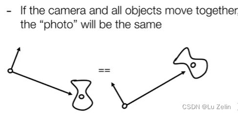
我们知道,当相机和物体进行相对运动时,不论怎么移动二者,我们看到的结果是一样的。
因此我们将相机从原本位置移动到原点位置,使得其Look-at direction看向 -z 方向,up-direction 是 y 正半轴。相机移动后,物体/场景跟着相机进行相同的移动,这样虽然进行了移动,但最终看到的结果是相同的。
这样做是因为可以简化很多操作,相机在(0,0,0)位置有很多的好处。
假设我们现在有一个相机,在 e 点上,gaze direction 是向量 g,up direction 是 t,我们要把点 e 给变成原点,向量 g 在 -z 轴上,t 在 y 正半轴上。
其基本思想是:
-
进行平移,将
e点移到原点。 -
旋转
g到-z方向上。 -
旋转
t到+y方向上。 -
旋转
g叉乘t得到的向量 到+x方向上。
由于我们说过一般是先进行线性变换再进行平移的,但在这里是先平移再线性变换,所以我们将T写在最右边。
平移矩阵很好写,难的是如何将g,t,g×t旋转到x,y,-z上。这时可以反过来想,我们知道g,t,g×t是如何用(x,y,z)表示的,我们只需要求出x,y,-z旋转到g,t,g×t的旋转矩阵,再加上旋转矩阵的逆矩阵 是这个旋转矩阵的转置矩阵这条性质,就可以巧妙的求出g,t,g×t给旋转到x,y,-z上的旋转矩阵。
View Transform主要做两步:
- 移动camera,使其位于world space的坐标原点,同样的将其余场景也进行相同的变换使其到应到的位置。
- 旋转camera,使得摄像机坐标系与世界坐标系重合。
Transformation(Projection)
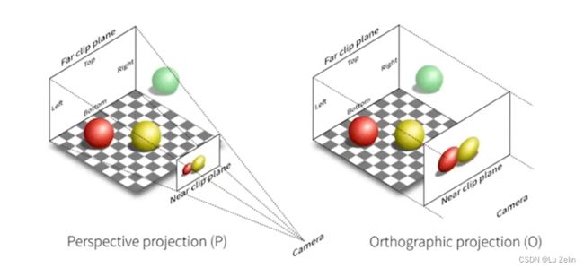
Orthographic projection (正交投影) :多用于工程制图
Perspective projection(透视投影):符合人眼的成像,会产生近大远小的效果,看起来平行线不会平行,延长的话会相交。
正交投影和透视投影本质的区别就是:是否有近大远小的效果
Orthographic projection
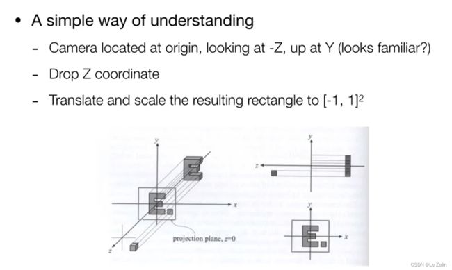
正交投影的思想:
Ⅰ. 我们设置camera于原点,看向-Z方向,向上是Y轴
Ⅱ. 然后我们舍弃Z轴也就是让所有物体都Z都等于0,从而我们实现了所有物体只在X轴和Y轴上
Ⅲ. 将其挤压到 [ − 1 , 1 ] ∗ [ − 1 , 1 ] [-1, 1] * [-1, 1] [−1,1]∗[−1,1]这么一个正方形内.
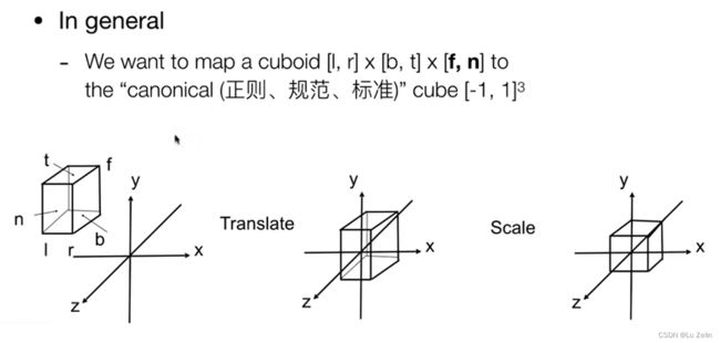
图形学中的实际操作:
我们定义一个立方体,left,right bottom,top far,near(但是注意我们是看向-Z方向的,far的Z轴值小,near的值大)
然后将其的中心平移到原点出,最后将其给拉成一个 [ − 1 , 1 ] 3 [-1, 1]^3 [−1,1]3的正则立方体。
具体的操作矩阵:
M o r t h o = [ 2 r − l 0 0 0 0 2 t − b 0 0 0 0 2 n − f 0 0 0 0 1 ] [ 1 0 0 − r + l 2 0 1 0 − t + b 2 0 0 1 − n + f 2 0 0 0 1 ] M_{ortho} =\left[ \begin{matrix} {2 \over {r-l}} & 0 & 0 & 0 \\ 0 & {2 \over {t-b}} & 0 & 0 \\ 0 & 0 & {2 \over {n-f}} & 0 \\ 0 & 0 & 0 & 1 \end{matrix} \right] \left[ \begin{matrix} 1 & 0 & 0 & -{{r+l} \over 2} \\ 0 & 1 & 0 & -{{t+b} \over 2} \\ 0 & 0 & 1 & -{{n+f} \over 2} \\ 0 & 0 & 0 & 1 \end{matrix} \right] Mortho= r−l20000t−b20000n−f200001 100001000010−2r+l−2t+b−2n+f1
具体来说第一个右侧矩阵是反向平移操作,将立方体的中心点平移到原点,类似二分找中点。第二个左侧矩阵是缩放到 [ − 1 , 1 ] 3 [-1, 1]^3 [−1,1]3内,因为边长是2,所以分子设置为2,相当于等比例交叉相乘。
Perspective projection
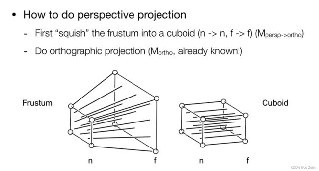
透视投影的思想:
Ⅰ. 将frustum给挤压成一个长方体,也就是将远平面压的和近平面一个大小。
Ⅱ. 做一次正交投影,将长方体的中心移到原点并将其压缩成 [ − 1 , 1 ] 3 [-1, 1]^3 [−1,1]3的正方体。
注意:
Ⅰ. 在挤压的过程中,近平面永远不会发生变化。
Ⅱ. 在挤压过程中,远平面上的Z值不会发生变化。
Ⅲ. 挤压过程中,远平面的中心点也不会发生变化。
关于Z值会发生改变的情况,可以想象一个场景。在你的面前是一条笔直的上山铁轨,随着距离越远,枕木之间的压缩距离应该越近。
我们知道如何做正交投影,那么接下来来讨论挤压这个frustum的矩阵如何求?
首先上图鼠标所在的右侧虚线并不是特指远平面,而是近平面到远平面之间的任意面(包含远平面)。
那么此时图中出现一组相似三角形,根据边的比例关系和已知的近平面Z值以及待挤压点的信息,可以得到挤压后点的 x ′ , y ′ x',y' x′,y′
在齐次坐标中的表示形式:
[ x y z 1 ] → [ n x / z n y / z u n k n o w n 1 ] = = [ n x n y s t i l l u n k n o w n z ] \left[ \begin{matrix} x \\ y \\ z \\1\end{matrix} \right] →\left[ \begin{matrix} nx/z \\ ny/z \\ unknown \\1 \end{matrix} \right] ==\left[ \begin{matrix} nx \\ ny \\ still \ \ \ unknown \\ z \end{matrix} \right] xyz1 → nx/zny/zunknown1 == nxnystill unknownz
挤压矩阵:
M p e r s p → o r t h o [ x y z 1 ] = [ n x n y u n k n o w n z ] M_{persp→ortho} \left[ \begin{matrix} x \\ y \\ z \\ 1 \end{matrix} \right] =\left[ \begin{matrix} nx \\ ny \\ unknown \\ z \end{matrix} \right] Mpersp→ortho xyz1 = nxnyunknownz
M p e r s p → o r t h o = [ n 0 0 0 0 n 0 0 ? ? ? ? 0 0 1 0 ] M_{persp→ortho}= \left[ \begin{matrix} n & 0 & 0 & 0 \\ 0 & n & 0 & 0 \\ ? & ? & ? & ? \\ 0 & 0 & 1 & 0 \end{matrix} \right] Mpersp→ortho= n0?00n?000?100?0
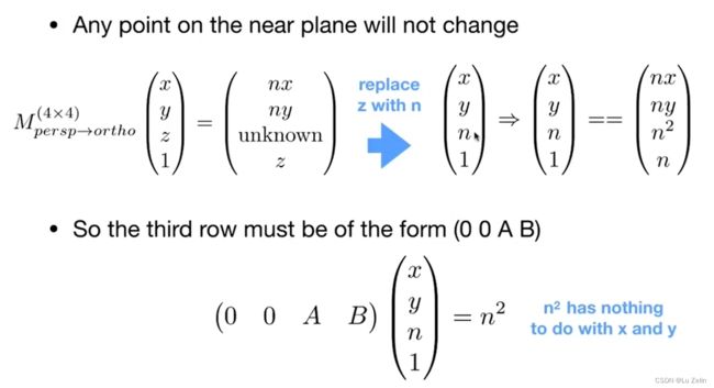
从而我们求出了除第三行以外的内容,接下来我们求第三行,但我们需要记住两点:
- 近平面上的任意一点都不会因变换而改变。
x、y依旧是变量,而替换之后的n为常量代表的是近平面的距离。总的来说就是用上述性质得到了一组
unknown为 n 2 n^2 n2的特例。
- 远平面上的任意一点的Z值都不会因变化而改变,并且中心点的X,Y也不会发生改变。
同样的,由于远平面任意一点的Z值不发生改变,取远平面的中心点(其被挤压后X和Y仍为0,且Z值不变),其坐标为(0,0,f,1)
最终推导出A,B的值,从而得到挤压矩阵 M p e r s p → o r t h o M_{persp→ortho} Mpersp→ortho。
M p e r s p → o r t h o = [ n 0 0 0 0 n 0 0 0 0 n + f − n f 0 0 1 0 ] M_{persp→ortho}= \left[ \begin{matrix} n & 0 & 0 & 0 \\ 0 & n & 0 & 0 \\ 0 & 0 & n+f & -nf \\ 0 & 0 & 1 & 0 \end{matrix} \right] Mpersp→ortho= n0000n0000n+f100−nf0
投影透视结论: M p e r s p = M o r t h o M p e r s p → o r t h o M_{persp}=M_{ortho}M_{persp→ortho} Mpersp=MorthoMpersp→ortho


