实验介绍
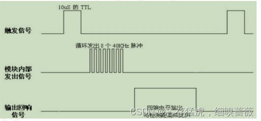
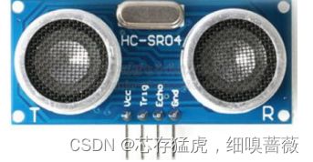
HC-SR04超声波传感器是一款测量距离的传感器。其原理是利用声波在遇到障碍物反射接收结合声波在空气中传播的速度计算的得出。
外观
管脚功能的定义
VCC:供电电源;Trig:触发信号;Echo:反馈信号;GND:电源地
硬件设计
软件设计
/* 深圳市普中科技有限公司(PRECHIN 普中)
技术支持:www.prechin.net
*
* 实验名称:超声波测距实验
*
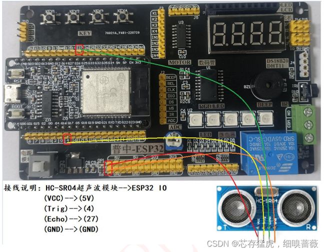
* 接线说明:HC-SR04超声波模块-->ESP32 IO
(VCC)-->(5V)
(Trig)-->(4)
(Echo)-->(27)
(GND)-->(GND)
*
* 实验现象:程序下载成功后,软件串口控制台间隔一段时间输出超声波模块测量距离
*
* 注意事项:需要在软件中选择"项目"-->"加载库"-->"添加一个.ZIP库..."-->选择到本实验目录下的1个压缩文件包“HCSR04-master.zip”安装即可。
* 该库使用方法可参考:https://github.com/Teknologiskolen/HCSR04/commits?author=theresetmaster
*/
#include "public.h"
#include
// AfstandsSensor(triggerPin, echoPin);
AfstandsSensor afstandssensor(4, 27);
void setup(){
Serial.begin(115200);
}
void loop(){
Serial.printf("测量距离:%.2fCM\r\n",afstandssensor.afstandCM());
delay(500);
}
/*
*/
实验介绍
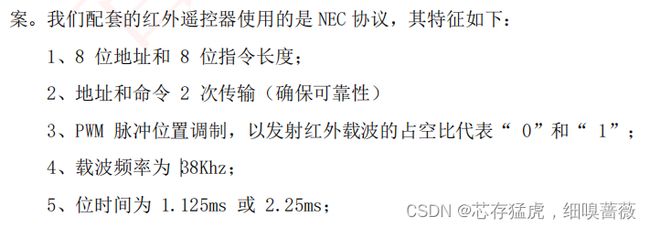
通常的红外遥控器是将遥控信号(二进制脉冲码)调制在38KHz的载波上,经过缓冲方法后送至红外发光二极管,转化为红外信号发射出去。
NEC码的位定义:1个脉冲对应560us的连续载波,一个逻辑1需要2.25ms(560us脉冲+1680us低电平),一个逻辑0的传输需要1.125ms(560us脉冲+560us低电平)。
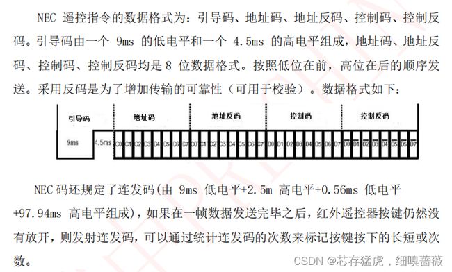
接收到的信号。逻辑1应该是560us低电平+1680us高电平,逻辑0应该是560us低电平+560us高电平。时序图如下图所示
指令格式如下:
红外接收设备
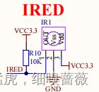
一般即是红外的三极管。从左至右,依此是1:VOUT,2:GND,3:VDD
硬件设计
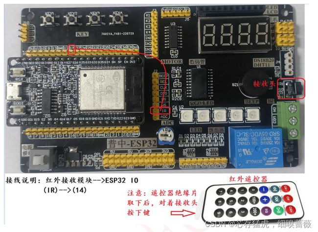
红外的IRED–VOUT与J2的IRED引脚相连接。即将ESP32的引脚与J2的IRED引脚相连接,即可以控制红外
软件设计
/* 深圳市普中科技有限公司(PRECHIN 普中)
技术支持:www.prechin.net
*
* 实验名称:红外遥控实验
*
* 接线说明:红外接收模块-->ESP32 IO
(IR)-->(14)
*
* 实验现象:程序下载成功后,当按下遥控器键时,软件串口控制台输出红外遥控器控制码(十六进制数)
*
* 注意事项:需要在软件中选择"项目"-->"加载库"-->"添加一个.ZIP库..."-->选择到本实验目录下的1个压缩文件包“IRremoteESP8266-master.zip”安装即可。
* 该库使用方法可参考:压缩包解压后可查看examples使用。
*/
#include "public.h"
#include
#include
#include
//红外控制引脚
#define kRecvPin 14
IRrecv irrecv(kRecvPin);
decode_results results;
void setup(){
Serial.begin(115200);
irrecv.enableIRIn();
}
void loop(){
if (irrecv.decode(&results))
{
// print() & println() can't handle printing long longs. (uint64_t)
serialPrintUint64(results.value, HEX);
Serial.println("");
irrecv.resume(); // Receive the next value
}
delay(100);
}
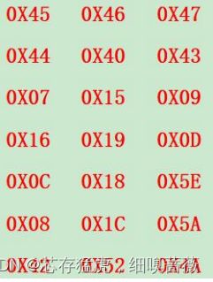
遥控器对应的键值表
实验介绍
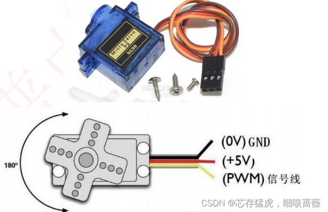
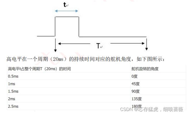
舵机是一种位置(角度)伺服的驱动器,适用那些需要角度不断变化并可以保持的控制系统。舵机是一种通俗的叫法,实际上是一个伺服马达。
让PWM产生周期为20ms,高电平0.5ms——2.5ms的方波。可以使用ESP32的PWM功能产生这样的方波,波形如下所示:
硬件设计
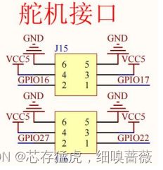
由图可知,板载了4路舵机接口均可连接到指定的IO。我们选择ESP32的17引脚
软件设计
/* 深圳市普中科技有限公司(PRECHIN 普中)
技术支持:www.prechin.net
*
* 实验名称:舵机实验
*
* 接线说明:SG90舵机模块-->ESP32 IO
橙色(信号线)-->(17)
红色(电源正)-->(5V)
褐色(电源负)-->(GND)
*
* 实验现象:程序下载成功后,SG90舵机循环以45°步进从0°旋转到180°
*
* 注意事项:
*/
#include "public.h"
#include "pwm.h"
//舵机控制引脚
#define servo_pin 17
//舵机控制
//degree:角度0-180
//返回值:输出对应角度PWM占空比
int servo_ctrl(u8 degree)
{
const float deadZone=6.4; //对应0.5ms(0.5/(20ms/256))
const float max=32; //对应2.5ms
if(degree<0)degree=0;
else if(degree>180)degree=180;
return (int)(((max-deadZone)/180)*degree+deadZone);
}
void setup(){
Serial.begin(115200);
pwm_init(servo_pin,8,50,8);
pwm_set_duty(8,servo_ctrl(0));
}
void loop(){
for(u8 i=0;i<=180;i+=45)
{
pwm_set_duty(8,servo_ctrl(i));
delay(1000);
}
}
pwm
#include "pwm.h"
//PWM初始化
//pin:引脚号
//chanel:PWM输出通道0-15,0-7高速通道,由80M时钟驱动,8-15低速通道,有1M时钟驱动
//freq:PWM输出频率,单位HZ
//resolution:PWM占空比的分辨率1-16,比如设置8,分辨率范围0-255
void pwm_init(u8 pin,u8 chanel,u8 freq,u8 resolution)
{
ledcSetup(chanel, freq, resolution);// PWM初始化
ledcAttachPin(pin, chanel);// 绑定PWM通道到GPIO上
}
//PWM占空比设置
void pwm_set_duty(u8 chanel,u16 duty)
{
ledcWrite(chanel,duty);// 改变PWM的占空比
}
实验介绍
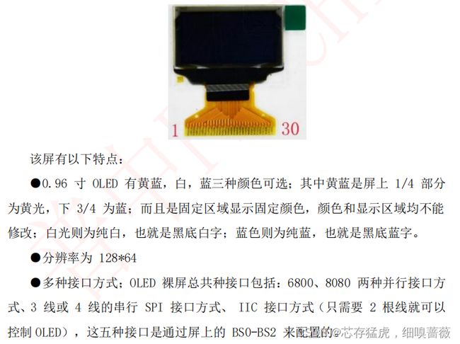
LCD需要背光,而OLED不需要,因为它自发光。目前使用的是0.96寸OLED显示屏,内部驱动芯片为SSD1306。
管脚:
GND:电源地,VDD:电源正(3-5.5V),SCK:I2C时钟管脚,SDA:I2C数据管脚
IIC是用于设备之间通信的双线协议,在物理层面,它由两条线组成:SCL和SDA,分别是时钟线和数据线。也就是说不同设备间通过这两根线可以进行通信。
ESP32有2个硬件IIC接口和N个软件IIC接口。硬件IIC总线默认IO如下:
IIC-0:18-SCL;19-SDA
IIC-1:25-SCL;26-SDA
硬件IIC接口可以通过配置可在任意IO口使用。软件IIC接口可通过配置在任意IO口使用,相当于使用IO口模拟IIC时序。本实验使用软件IIC与OLED通信。
硬件设计
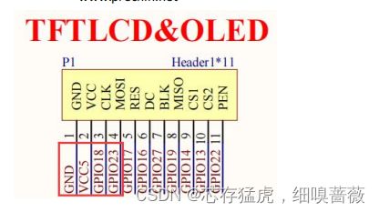
GPIO18、GPIO32分别于SCL和SDA相连接
软件设计
OLED的IIC地址默认是0x3C
/* 深圳市普中科技有限公司(PRECHIN 普中)
技术支持:www.prechin.net
*
* 实验名称:OLED液晶显示实验
*
* 接线说明:OLED(IIC)液晶模块-->ESP32 IO
GND-->(GND)
VCC-->(5V)
SCL-->(18)
SDA-->(23)
*
* 实验现象:程序下载成功后,OLED液晶屏显示字符信息
*
* 注意事项:需要在软件中选择"项目"-->"加载库"-->"添加一个.ZIP库..."-->选择到本实验目录下的1个压缩文件包“esp8266-oled-ssd1306-master.zip”安装即可。
* 该库使用方法可参考:压缩包解压后可查看examples使用。
*/
#include "public.h"
#include // Only needed for Arduino 1.6.5 and earlier
#include "SSD1306Wire.h" // legacy: #include "SSD1306.h"
#include "images.h"
#define DEMO_DURATION 3000
typedef void (*Demo)(void);
int demoMode = 0;
int counter = 1;
//OLED引脚定义
#define SDA 23
#define SCL 18
SSD1306Wire display(0x3c, SDA, SCL);
void setup(){
Serial.begin(115200);
display.init();//初始化UI
display.flipScreenVertically();//垂直翻转屏幕设置
display.setFont(ArialMT_Plain_24);//设置字体大小
display.drawString(0, 0, "Hello World");//显示
display.display();//将缓存数据写入到显示器
}
void drawFontFaceDemo() {
// Font Demo1
// create more fonts at http://oleddisplay.squix.ch/
display.setTextAlignment(TEXT_ALIGN_LEFT);
display.setFont(ArialMT_Plain_10);
display.drawString(0, 0, "Hello world");
display.setFont(ArialMT_Plain_16);
display.drawString(0, 10, "Hello world");
display.setFont(ArialMT_Plain_24);
display.drawString(0, 26, "Hello world");
}
void drawTextFlowDemo() {
display.setFont(ArialMT_Plain_10);
display.setTextAlignment(TEXT_ALIGN_LEFT);
display.drawStringMaxWidth(0, 0, 128,
"Lorem ipsum\n dolor sit amet, consetetur sadipscing elitr, sed diam nonumy eirmod tempor invidunt ut labore." );
}
void drawTextAlignmentDemo() {
// Text alignment demo
display.setFont(ArialMT_Plain_10);
// The coordinates define the left starting point of the text
display.setTextAlignment(TEXT_ALIGN_LEFT);
display.drawString(0, 10, "Left aligned (0,10)");
// The coordinates define the center of the text
display.setTextAlignment(TEXT_ALIGN_CENTER);
display.drawString(64, 22, "Center aligned (64,22)");
// The coordinates define the right end of the text
display.setTextAlignment(TEXT_ALIGN_RIGHT);
display.drawString(128, 33, "Right aligned (128,33)");
}
void drawRectDemo() {
// Draw a pixel at given position
for (int i = 0; i < 10; i++) {
display.setPixel(i, i);
display.setPixel(10 - i, i);
}
display.drawRect(12, 12, 20, 20);
// Fill the rectangle
display.fillRect(14, 14, 17, 17);
// Draw a line horizontally
display.drawHorizontalLine(0, 40, 20);
// Draw a line horizontally
display.drawVerticalLine(40, 0, 20);
}
void drawCircleDemo() {
for (int i = 1; i < 8; i++) {
display.setColor(WHITE);
display.drawCircle(32, 32, i * 3);
if (i % 2 == 0) {
display.setColor(BLACK);
}
display.fillCircle(96, 32, 32 - i * 3);
}
}
void drawProgressBarDemo() {
int progress = (counter / 5) % 100;
// draw the progress bar
display.drawProgressBar(0, 32, 120, 10, progress);
// draw the percentage as String
display.setTextAlignment(TEXT_ALIGN_CENTER);
display.drawString(64, 15, String(progress) + "%");
}
void drawImageDemo() {
// see http://blog.squix.org/2015/05/esp8266-nodemcu-how-to-create-xbm.html
// on how to create xbm files
display.drawXbm(34, 14, WiFi_Logo_width, WiFi_Logo_height, WiFi_Logo_bits);
}
Demo demos[] = {drawFontFaceDemo, drawTextFlowDemo, drawTextAlignmentDemo, drawRectDemo, drawCircleDemo, drawProgressBarDemo, drawImageDemo};
int demoLength = (sizeof(demos) / sizeof(Demo));
long timeSinceLastModeSwitch = 0;
void loop(){
// clear the display
display.clear();
// draw the current demo method
demos[demoMode]();
display.setFont(ArialMT_Plain_10);
display.setTextAlignment(TEXT_ALIGN_RIGHT);
display.drawString(128, 54, String(millis()));
// write the buffer to the display
display.display();
if (millis() - timeSinceLastModeSwitch > DEMO_DURATION) {
demoMode = (demoMode + 1) % demoLength;
timeSinceLastModeSwitch = millis();
}
counter++;
delay(10);
}
实验介绍
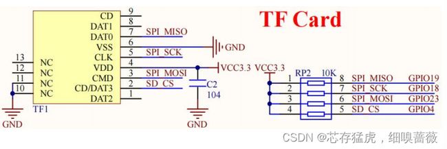
开发板已经板载了TF卡座,可使用TF卡插入使用。
ESP32-WROOM-32可使用SPI口与SD卡进行通信。
SPI的全称是“Serial Peripheral Interface”,串行外围接口、SPI是一种高速的、全双工、同步的通信总线。在芯片的管脚上只占用4根线,节约了芯片的管脚,同时为PCB的布局上节省空间,提供方便。
SPI接口一般使用4条线通信,事实上只需要3条线就可以进行SPI通信(单向传输时),其中3条为SPI总线(MISO、MOSI、SCLK),一条为SPI片选信号线(CS)。
ESP32有两个硬件SPI通道允许更高速率传输(到达80MHz)。也可以配置成任意引脚,但相关引脚要符合输入输出的方向性。通过自定义引脚而非默认引脚,会降低传输速度,上限为40Mhz。SPI总线默认引脚如图:
HSPI(id=1) SCLk14;MOSI13;MISO12
VSPI(id=2) SCLK18;MOSI23;MISO19
id=1的HSPI已经连接到模块的SPI-FLASH上,不要去使用。因此可以使用id=2的SPI与SD卡进行通信
硬件设计
由图可知,SD卡接口均连接到指定IO处。
软件设计
在sd卡中创建test.txt文档。打开文档写入内容后关闭;再打开文档读取内容
/* 深圳市普中科技有限公司(PRECHIN 普中)
技术支持:www.prechin.net
*
* 实验名称:SD卡实验
*
* 接线说明:SD卡模块-->ESP32 IO
(DAT0)(MISO)-->(19)
(CMD)(MOSI)-->(23)
(CLK)(SCK)-->(18)
(CD/DAT3)(CS)-->(4)
*
* 实验现象:程序下载成功后,在SD卡指定目录下新建text.txt文件,写入信息,然后读取文件,在串口
控制台上输出读取文件中的字符信息。
*
* 注意事项:
*/
#include "public.h"
#include
#include
File myFile;
void setup(){
Serial.begin(115200);
Serial.print("Initializing SD card...");
SPIClass spi = SPIClass(VSPI);
spi.begin(18 /* SCK */, 19 /* MISO */, 23 /* MOSI */, 4 /* SS */);
// SD.begin(4 /* SS */, spi, 80000000);
if (!SD.begin(4)) {
Serial.println("initialization failed!");
return;
}
Serial.println("initialization done.");
// open the file. note that only one file can be open at a time,
// so you have to close this one before opening another.
myFile = SD.open("/test.txt", FILE_WRITE);
// if the file opened okay, write to it:
if (myFile) {
Serial.print("Writing to test.txt...");
myFile.println("testing 1, 2, 3.");
// close the file:
myFile.close();
Serial.println("done.");
} else {
// if the file didn't open, print an error:
Serial.println("error opening test.txt");
}
// re-open the file for reading:
myFile = SD.open("/test.txt");
if (myFile) {
Serial.println("test.txt:");
// read from the file until there's nothing else in it:
while (myFile.available()) {
Serial.write(myFile.read());
}
// close the file:
myFile.close();
} else {
// if the file didn't open, print an error:
Serial.println("error opening test.txt");
}
}