[LabVIEW]Phase Shift Keying
| Introduction In this lab, I learnt the principle of Phase Shift Keying (include Quadrature Phase Shift Keying and Binary Phase Shift Keying). Then I design a LabVIEW program to simulate these two kinds of Phase Shift Keying to verify the theorem knowledge. I try to compare the performance of these two kinds of Phase Shift Keying by using the result of the LabVIEW program. Principle of Phase Shift Keying
The most straightforward type of PSK is called binary phase shift keying (BPSK), where “binary” refers to the use of two-phase offsets (one for logic high, one for logic low). We can intuitively recognize that the system will be more robust if there is greater separation between these two phases—of course it would be difficult for a receiver to distinguish between a symbol with a phase offset of 90° and a symbol with a phase offset of 91°. We only have 360° of phase to work with, so the maximum difference between the logic-high and logic-low phases is 180°. But we know that shifting a sinusoid by 180° is the same as inverting it; thus, we can think of BPSK as simply inverting the carrier in response to one logic state and leaving it alone in response to the other logic state.
To take this a step further, we know that multiplying a sinusoid by negative one is the same as inverting it. This leads to the possibility of implementing BPSK using the following basic hardware configuration:
However, this scheme could easily result in high-slope transitions in the carrier waveform: if the transition between logic states occurs when the carrier is at its maximum value, the carrier voltage has to rapidly move to the minimum voltage.
High-slope events such as these are undesirable because they generate higher-frequency energy that could interfere with other RF signals. Also, amplifiers have limited ability to produce high-slope changes in output voltage.
If we refine the above implementation with two additional features, we can ensure smooth transitions between symbols. First, we need to ensure that the digital bit period is equal to one or more complete carrier cycles. Second, we need to synchronize the digital transitions with the carrier waveform. With these improvements, we could design the system such that the 180° phase change occurs when the carrier signal is at (or very near) the zero-crossing.
BPSK transfers one bit per symbol, which is what we’re accustomed to so far. Everything we’ve discussed with regard to digital modulation has assumed that the carrier signal is modified according to whether a digital voltage is logic low or logic high, and the receiver constructs digital data by interpreting each symbol as either a 0 or a 1.
Before we discuss quadrature phase shift keying (QPSK), we need to introduce the following important concept: There is no reason why one symbol can transfer only one bit. It’s true that the world of digital electronics is built around circuitry in which the voltage is at one extreme or the other, such that the voltage always represents one digital bit. But RF is not digital; rather, we’re using analog waveforms to transfer digital data, and it is perfectly acceptable to design a system in which the analog waveforms are encoded and interpreted in a way that allows one symbol to represent two (or more) bits.
QPSK is a modulation scheme that allows one symbol to transfer two bits of data. There are four possible two-bit numbers (00, 01, 10, 11), and consequently we need four phase offsets. Again, we want maximum separation between the phase options, which in this case is 90°.
The advantage is higher data rate: if we maintain the same symbol period, we can double the rate at which data is moved from transmitter to receiver. The downside is system complexity. (You might think that QPSK is also significantly more susceptible to bit errors than BPSK, since there is less separation between the possible phase values. This is a reasonable assumption, but if you go through the math it turns out that the error probabilities are actually very similar.) Lab results & Analysis:
These two kinds of mapping methods are come from the theorem knowledge.
Figure 1 Mapping of BPSK
Figure 2 Mapping of QPSK
Figure 3 Digital demodulation of QPSK
Figure 4 Digital demodulation of BPSK
Figure 5 configuration of BPSK The parameter M is representing the number of the mapping cases, for BPSK, the mapping case is only 1 and -1 so that we need to configurate the value of M to be 2.
Figure 6 input and output of BPSK
Figure 7 RF
Figure 8 I signal Figure 8 shows that the signal in In-phase component.
Figure 9 Pulse Shape Figure 9 shows that the convolution of the signal after the interpolation and pulse signal.
Figure 10 Q signal Figure 10 shows that the quadrature component of the signal.
Figure 11 IQ graph Figure 11 shows that IQ graph of the BPSK.
Figure 12 configuration of QPSK The parameter M is representing the number of the mapping cases, for QPSK, the mapping cases are only (0.707+0.707i), (0.707-0.707i), (-0.707+0.707i) and (-0.707-0.707i) so that we need to configurate the value of M to be 4.
Figure 13 input and output of QPSK
Figure 14 RF
Figure 15 I signal Figure 15 shows that the signal in In-phase component. We can see the waveform in this figure are still have some distortion. But the general trend and the waveform are similar.
Figure 16 Pulse Shape Figure 16 shows that the convolution of the signal after the interpolation and pulse signal.
Figure 17 Q signal Figure 17 shows that the quadrature component of the signal.
Figure 18 IQ graph Figure 18 shows that IQ graph of the QPSK. Then we can adjust the value of Eb/N0 to verify the theorem knowledge. We decrease the value of Eb/N0 to -20, and see what happen.
Figure 19 example of output hen we can adjust the value of Eb/N0 to verify the theorem knowledge. We decrease the value of Eb/N0 to -20dB, and see what happen then we can try some times to compare the bits error rate of the system when Eb/N0 is -20dB.
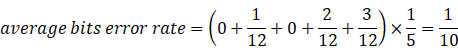
Figure 20 five output when Eb/N0 is -20dB We can count the number of the error bits to compute the bits error rate, the new can get the average number of these five bits error rate. average bits error rate=0+112+0+212+312×15=110 We can adjust the value of Eb/N0 continually, and compare the bits error rate of different values of Eb/N0. And we find: When the value of Eb/N0 is bigger than -10dB, the bits error rate is almost zero. When the value of Eb/N0 is smaller than -10dB but bigger than -20dB, the bits error rate is between zero and 10% When the value of Eb/N0 is smaller than -20dB but bigger than -30dB the bits error rate is almost 35% When the value of Eb/N0 is smaller than -30dB, the bits error rate is almost bigger than 50%.
|
|
| Experience: In this lab, I learnt the principle of Phase Shift Keying (include Quadrature Phase Shift Keying and Binary Phase Shift Keying). Then I design a LabVIEW program to simulate these two kinds of Phase Shift Keying to verify the theorem knowledge. I try to compare the performance of these two kinds of Phase Shift Keying by using the result of the LabVIEW program. In this lab, I do not know the meaning of the parameter M, so the performance of BPSK is abnormal and terrible. By using some materials and paper, I know the principle of Eb/N0 and M. So that I can get the right results of this lab. At first, I think the result of BPSK and QPSK are same by using the same digital demodulation methods, but in fact they are different. Because the demodulation in BPSK is one bit by one bit. But the same work or step in the QPSK are processed two bit pri time. So, the results are different. Feedback: The input data scale is too small to determine the error bit rate. Because when the value of Eb/N0 is large (more than -10 dB), the error bits rate is very small. It is such different to get the error bits rate by just a short input data. If we use a longer input bit array, we will get the error bits rate more accurate with different situations. |
|
| Score |
|
![[LabVIEW]Phase Shift Keying_第1张图片](http://img.e-com-net.com/image/info8/9469dd3ed24148689ca137de6c07509e.jpg)
![[LabVIEW]Phase Shift Keying_第2张图片](http://img.e-com-net.com/image/info8/42ebe5c77c3e4f8a8708be5aa7ba0e95.jpg)
![[LabVIEW]Phase Shift Keying_第3张图片](http://img.e-com-net.com/image/info8/9d4be618eb3c4b25b2236785ceb13475.jpg)
![[LabVIEW]Phase Shift Keying_第4张图片](http://img.e-com-net.com/image/info8/10ee37f3b86143379e4c399d721c5ff5.jpg)
![[LabVIEW]Phase Shift Keying_第5张图片](http://img.e-com-net.com/image/info8/0a716be674b74240ae118ac84e802659.jpg)
![[LabVIEW]Phase Shift Keying_第6张图片](http://img.e-com-net.com/image/info8/f707bc73f71347cf8cf6466bf8b20269.jpg)
![[LabVIEW]Phase Shift Keying_第7张图片](http://img.e-com-net.com/image/info8/5ab45a9738ba423394426c777dce137b.jpg)
![[LabVIEW]Phase Shift Keying_第8张图片](http://img.e-com-net.com/image/info8/b5d18bfc4b5f4d03931393190431ffe6.jpg)
![[LabVIEW]Phase Shift Keying_第9张图片](http://img.e-com-net.com/image/info8/9341ef2ea2b148bd90665e13d1629e72.jpg)
![[LabVIEW]Phase Shift Keying_第10张图片](http://img.e-com-net.com/image/info8/0e9263fd728b46179ca1cb28584a9b5e.jpg)
![[LabVIEW]Phase Shift Keying_第11张图片](http://img.e-com-net.com/image/info8/b1d4a8b8aeaf4e738a672d82a6343ab9.jpg)
![[LabVIEW]Phase Shift Keying_第12张图片](http://img.e-com-net.com/image/info8/2a2b9104ae164f64b2ec4e8a5baaad5c.jpg)
![[LabVIEW]Phase Shift Keying_第13张图片](http://img.e-com-net.com/image/info8/9726506aed184e6783b5704a96ecf0ab.jpg)
![[LabVIEW]Phase Shift Keying_第14张图片](http://img.e-com-net.com/image/info8/3f6d521db66e40c099eeed9989ee0611.jpg)
![[LabVIEW]Phase Shift Keying_第15张图片](http://img.e-com-net.com/image/info8/96d92bd5ac8f430b91e3c5a0a85dd27d.jpg)
![[LabVIEW]Phase Shift Keying_第16张图片](http://img.e-com-net.com/image/info8/30b21132bec9482f8277544692dce5e2.jpg)
![[LabVIEW]Phase Shift Keying_第17张图片](http://img.e-com-net.com/image/info8/08d0b3a875c54157b9ae1dbc60114bd0.jpg)
![[LabVIEW]Phase Shift Keying_第18张图片](http://img.e-com-net.com/image/info8/45fda56404364459a4ac6e28f6e68265.jpg)
![[LabVIEW]Phase Shift Keying_第19张图片](http://img.e-com-net.com/image/info8/1beacf5b125a4e0880b91921871f435f.jpg)
![[LabVIEW]Phase Shift Keying_第20张图片](http://img.e-com-net.com/image/info8/ce8b9c90c2f04bdd85f4a0306b536b6b.jpg)
![[LabVIEW]Phase Shift Keying_第21张图片](http://img.e-com-net.com/image/info8/f1139dd32566419e917dbfe56d3477b5.jpg)
![[LabVIEW]Phase Shift Keying_第22张图片](http://img.e-com-net.com/image/info8/c6970579cbd84898b547614d83e58e5f.jpg)
![[LabVIEW]Phase Shift Keying_第23张图片](http://img.e-com-net.com/image/info8/d9b1370db765408aa3bae6bc20ca9105.jpg)
![[LabVIEW]Phase Shift Keying_第24张图片](http://img.e-com-net.com/image/info8/5471b9f55a1441f39655d061324eac6d.jpg)
![[LabVIEW]Phase Shift Keying_第25张图片](http://img.e-com-net.com/image/info8/81712c3015224289ad46dad6f551eb4d.jpg)
![[LabVIEW]Phase Shift Keying_第26张图片](http://img.e-com-net.com/image/info8/39bc4cfa9b59458db7a14ed26e7279be.jpg)
![[LabVIEW]Phase Shift Keying_第27张图片](http://img.e-com-net.com/image/info8/86b57a1666c64892af03e21ac671fb07.jpg)
![[LabVIEW]Phase Shift Keying_第28张图片](http://img.e-com-net.com/image/info8/7d375b49fae2451ea10b2927dc7ae25e.jpg)