华为ENSP网络设备配置实战5(OSPF跨域+BGP+VPN+单臂路由)
题目要求
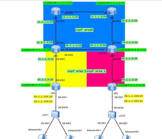
1、正确配置各设备接口
2、按图配置OSPF各区域
3、loopback口通过OSPF连通
4、AR3与AR4互联链路为备用链路,合理规划OSPF开销
5、正确配置-spi、-spims
6、建立mpls邻居
7、AR3、AR4、AR5、AR6分别与AR1、AR2建立BGP邻居
8、AR5、AR6作为PC机网关设备
9、PC1、PC3由VPN-spi承载,PC2、PC4由VPN-spims承载
10、PC1、PC3互通,PC2、PC4互通

解题过程
这道题和华为ENSP网络设备配置实战4类似,就是多了一个OSPF跨域,所以相同的部分,请看前篇,本篇不做过多赘述。
1、正确配置各设备接口,按图配置OSPF各区域,loopback口通过OSPF连通,AR3与AR4互联链路为备用链路,合理规划OSPF开销。
1.1、 按照拓扑图,各个设备起名
sys (进入系统视图)
sysname AR1(AR2-AR6、SW1-SW2等设备参照如此)
undo info-center enable (un in en关闭设备消息提示,可做可不做)
1.2、给路由器AR1~4配置loopback地址,并在相应接口配置IP地址
在设备AR1上:
int LoopBack 0  (进loopback 口)
ip add 1.1.1.1 32
int g 0/0/0   (进拓扑图上提示的接口)
ip add 12.1.1.1 24
int g 0/0/1 (进拓扑图上提示的接口)
ip add 13.1.1.1 24
Quit
AR3:
int LoopBack 0
ip address 3.3.3.3 32
int g 0/0/1
ip address 13.1.1.3 24
int g 0/0/0
ip address 34.1.1.3 24
Quit
int g 0/0/2
ip address 35.1.1.3 24
quit
AR5:
int LoopBack 0
ip address 5.5.5.5 32
int g 0/0/2
ip address 35.1.1.5 24
Quit
同理,AR2、AR4、AR6分别参照1、3、5进行相应的配置即可。
1.3、宣告路由AR1~4,让他们能通过osfp学到各个router-id和下挂的接口地址
在设备AR1上:
ospf 1 router-id 1.1.1.1
(配置ospf路由id)
area 0  (默认area 0)
network 1.1.1.1 0.0.0.0 (宣告router-id)
network 13.1.1.0 0.0.0.255(宣告接口)
network 12.1.1.0 0.0.0.255 (宣告接口)
quit
quit
AR3:
ospf 1 router-id 3.3.3.3
area 0
network 3.3.3.3 0.0.0.0
network 13.1.1.3 0.0.0.0
network 34.1.1.3 0.0.0.0
Area 1
Net 35.1.1.3 0.0.0.0
quit
quit
AR5:
ospf 1 router-id 5.5.5.5
area 1
network 5.5.5.5 0.0.0.0
network 35.1.1.5 0.0.0.0
quit
quit
可以看出来,AR3多了一个area 1区域的宣告,而AR5只有area 1区域的宣告。同理,AR2、AR4、AR6分别参照1、3、5进行相应的配置即可。
1.4、设置路由开销,根据题目要求配置AR3和AR4
int g 0/0/2   (进接口)
ospf cost 2 (改cost)
AR4:
int g 0/0/2
ospf cost 2
2、正确配置-spi、-spims,建立mpls邻居,AR3、AR4、AR5、AR6分别与AR1、AR2建立BGP邻居
2.1、 给各个路由设备,及所在接口配置mpls标签
在设备AR1上:
mpls lsr-id 1.1.1.1(配置标签号)
mpls (配置mpls)
mpls ldp(配置mpls ldp)
int g 0/0/0 (进接口)
mpls (配置mpls)
mpls ldp(配置mpls ldp)
int g 0/0/1(同上)
mpls
mpls ldp
quit
AR3:
mpls lsr-id 3.3.3.3
mpls
mpls ld
int g 0/0/1
mpls
mpls ldp
int g 0/0/2
mpls
mpls ldp
quit
AR5:
mpls lsr-id 5.5.5.5
mpls
mpls ld
int g 0/0/2
mpls
mpls ldp
quit
同理,AR2、AR4、AR6分别参照1、3、5进行相应的配置即可。
2.2、 根据第四问的要求,给各个路由设备,配置spi和spi两条业务
在设备AR1、AR2、AR3、AR4、AR5、AR6上都配置好此命令:
ip -instance spi (配置spi业务)
route-distinguisher 100:1(根据题目来)
-target 100:1(根据题目来)
quit
quit
ip -instance spims(配置spims业务)
route-distinguisher 200:1(根据题目来)
-target 200:1(根据题目来)
Quit
quit
2.3、各个设备,配置bgp协议
在设备AR1上:
bgp 100
router-id 1.1.1.1
peer 2.2.2.2 as-number 100
peer 3.3.3.3 as-number 100
peer 4.4.4.4 as-number 100
peer 5.5.5.5 as-number 100
peer 6.6.6.6 as-number 100
peer 2.2.2.2 connect-interface LoopBack 0
peer 3.3.3.3 connect-interface LoopBack 0
peer 4.4.4.4 connect-interface LoopBack 0
peer 5.5.5.5 connect-interface LoopBack 0
peer 6.6.6.6 connect-interface LoopBack 0
peer 2.2.2.2 enable
peer 3.3.3.3 enable
peer 4.4.4.4 enable
peer 5.5.5.5 enable
peer 6.6.6.6 enable

ip v4(因为要,所以配置v4)
peer 2.2.2.2 enable
peer 3.3.3.3 enable
peer 4.4.4.4 enable
peer 5.5.5.5 enable
peer 6.6.6.6 enable
peer 3.3.3.3 reflect-client
peer 4.4.4.4 reflect-client
peer 5.5.5.5 reflect-client
peer 6.6.6.6 reflect-client
ip  spims
quit
ip  spi
quit
AR3上:
bgp 100
router-id 3.3.3.3
peer 1.1.1.1 as-number 100
peer 2.2.2.2 as-number 100
peer 1.1.1.1 connect-interface LoopBack 0
peer 2.2.2.2 connect-interface LoopBack 0
peer 1.1.1.1 enable
peer 2.2.2.2 enable

ip v4
peer 1.1.1.1 enable
peer 2.2.2.2 enable
ip  spims
quit
ip  spi
quit
AR5上:
bgp 100
router-id 5.5.5.5
peer 1.1.1.1 as-number 100
peer 2.2.2.2 as-number 100
peer 1.1.1.1 connect-interface LoopBack 0
peer 2.2.2.2 connect-interface LoopBack 0
peer 1.1.1.1 enable
peer 2.2.2.2 enable

ip v4
peer 1.1.1.1 enable
peer 2.2.2.2 enable
quit
ipv4-family -instance spi
imp dir (这里要引入直连)
ipv4-family -instance spims
imp dir (这里要引入直连)
quit
quit
同理,AR2、AR4、AR6分别参照1、3、5进行相应的配置即可。
3、 AR5、AR6作为PC机网关设备。PC1、PC3由VPN-spi承载,PC2、PC4由VPN-spims承载。
3.1、这两个其实是一问,即配置单臂路由
AR3上:
int g 0/0/1.13(进子接口)
ip binding  -instance  spi(绑定spi业务)
ip add  10.1.1.254 24(配置网关)
dot1q termination vid 13(子接口vlan id 号)
arp broadcast  enable (开启广播)

int g 0/0/1.24(进子接口)
ip binding  -instance  spims(绑定spims业务)
ip add  20.1.1.254 24(配置网关)
dot1q termination vid 24
arp broadcast  enable
quit
AR4上:
int g 0/0/1.13
ip binding  -instance  spi
ip add  30.1.1.254 24
dot1q termination vid 13
arp broadcast  enable

int g 0/0/1.24
ip binding  -instance  spims
ip add  40.1.1.254 24
dot1q termination vid 24
arp broadcast  enable
quit
然后就是配置下面的交换机SW1和SW2。
在SW1、SW2上:
v b 13 24 (vlan划分)
int g 0/0/24(进接口)
p l t (trunk链路)
p t a v 13 24(只允许13、24vlan通过)
(邢工是 port trunk all-pass vlan all,看题目要求)
int g 0/0/1(进接口)
p l a (access链路)
p d v 13(端口下的默认vlan)
int g 0/0/2
p l a  (access链路)
p d v 24(端口下的默认vlan)
至此,所有设备都已经配通了。
