连续类功放通解1:连续类单管功率放大器现有理论
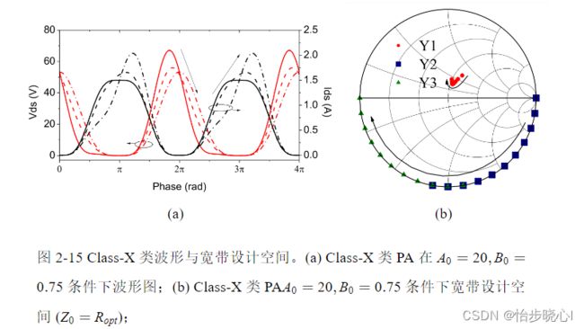
连续类功放通解1:连续类单管功率放大器现有理论
本次内容理论性较强,适合对功率放大器理论研究比较感兴趣以及想发论文的小朋友,着重探讨现有的一些带宽拓展模式(也就是连续类)的基本实现原理,并给出其通用的分析求解方法。
1、现有宽带模式概述
1.1 连续F/F-1类
在此主要介绍连续F类,连续F/F-1类PA的归一化电压和电流波形分别如下所示,可以看到连续F类的电流波形与B类PA波形相同,电压波形是在原来的基础上乘以了 ( 1 − γ sin ( θ ) ) (1 - \gamma \sin (\theta )) (1−γsin(θ)),在此将 ( 1 − γ sin ( θ ) ) (1 - \gamma \sin (\theta )) (1−γsin(θ))成为连续因子。而连续F-1的波形是将连续F类的电压电流交换即可:
V C F = ( 1 − 2 3 cos θ ) 2 ⋅ ( 1 + 1 3 cos θ ) ⋅ ( 1 − γ sin θ ) I C F = 1 π + 1 2 cos θ + 2 3 π cos ( 2 θ ) \begin{aligned} &{V_{CF}} = {\left( {1 - \frac{2}{{\sqrt 3 }}\cos \theta } \right)^2} \cdot \left( {1 + \frac{1}{{\sqrt 3 }}\cos \theta } \right) \cdot (1 - \gamma \sin \theta )\\ &{I_{CF}} = \frac{1}{\pi } + \frac{1}{2}\cos \theta + \frac{2}{{3\pi }}\cos (2\theta ) \end{aligned} VCF=(1−32cosθ)2⋅(1+31cosθ)⋅(1−γsinθ)ICF=π1+21cosθ+3π2cos(2θ)
V C F = 1 π + 1 2 cos θ + 2 3 π cos ( 2 θ ) I C F = ( 1 − 2 3 cos θ ) 2 ⋅ ( 1 + 1 3 cos θ ) ⋅ ( 1 − γ sin θ ) \begin{aligned} &{V_{CF}} = \frac{1}{\pi } + \frac{1}{2}\cos \theta + \frac{2}{{3\pi }}\cos (2\theta )\\ &{I_{CF}} = {\left( {1 - \frac{2}{{\sqrt 3 }}\cos \theta } \right)^2} \cdot \left( {1 + \frac{1}{{\sqrt 3 }}\cos \theta } \right) \cdot (1 - \gamma \sin \theta ) \end{aligned} VCF=π1+21cosθ+3π2cos(2θ)ICF=(1−32cosθ)2⋅(1+31cosθ)⋅(1−γsinθ)
连续F类波形与连续F-1类波形如下所示:
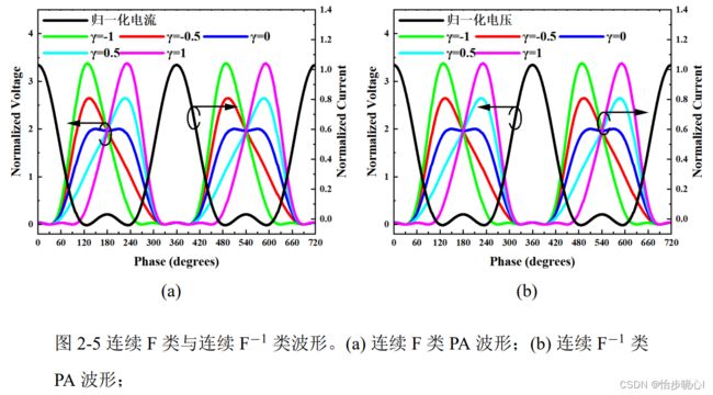
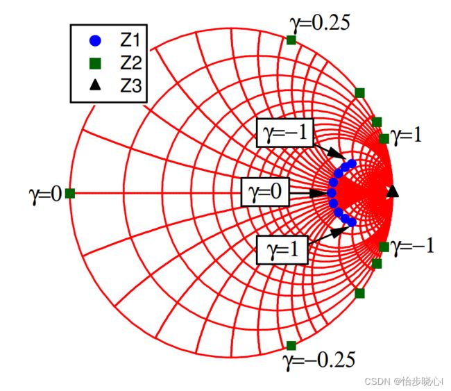
连续F类与连续 F − 1 \rm F^{ - 1} F−1类PA的阻抗空间表达式如下所示:
{ Z 1 f , C − F = ( 2 3 + j γ ) R o p t Z 2 f , C − F = − j 7 3 π 24 R o p t Z 3 f , C − F = ∞ { Y 1 f , C − F − 1 = ( 0.43 2 + j 0.37 2 γ ) G o p t Y 2 f , C − F − 1 = − j 0.98 2 γ G o p t Y 3 f , C − F − 1 = ∞ G o p t = 1 / R o p t \left\{ \begin{aligned} &{Z_{1f,C - F}} = \left( {\frac{2}{{\sqrt 3 }} + j\gamma } \right){R_{opt}}\\ &{Z_{2f,C - F}} = - j\frac{{7\sqrt 3 \pi }}{{24}}{R_{opt}}\\ &{Z_{3f,C - F}} = \infty \end{aligned} \right.{\kern 1pt} {\kern 1pt} {\kern 1pt} {\kern 1pt} {\kern 1pt} {\kern 1pt} {\kern 1pt} {\kern 1pt} {\kern 1pt} {\kern 1pt} {\kern 1pt} {\kern 1pt} {\kern 1pt} {\kern 1pt} {\kern 1pt} {\kern 1pt} {\kern 1pt} {\kern 1pt} {\kern 1pt} {\kern 1pt} {\kern 1pt} {\kern 1pt} {\kern 1pt} {\kern 1pt} {\kern 1pt} {\kern 1pt} {\kern 1pt} {\kern 1pt} {\kern 1pt} {\kern 1pt} {\kern 1pt} {\kern 1pt} {\kern 1pt} {\kern 1pt} {\kern 1pt} {\kern 1pt} {\kern 1pt} {\kern 1pt} {\kern 1pt} {\kern 1pt} {\kern 1pt} \left\{ \begin{aligned} &{Y_{1f,C - {F^{ - 1}}}} = \left( {0.43\sqrt 2 + j0.37\sqrt 2 \gamma } \right){G_{opt}}\\ &{Y_{2f,C - {F^{ - 1}}}} = - j0.98\sqrt 2 \gamma {G_{opt}}\\ &{Y_{3f,C - {F^{ - 1}}}} = \infty \\ &{G_{opt}} = 1/{R_{opt}} \end{aligned} \right. ⎩ ⎨ ⎧Z1f,C−F=(32+jγ)RoptZ2f,C−F=−j2473πRoptZ3f,C−F=∞⎩ ⎨ ⎧Y1f,C−F−1=(0.432+j0.372γ)GoptY2f,C−F−1=−j0.982γGoptY3f,C−F−1=∞Gopt=1/Ropt
连续F类与连续 F − 1 \rm F^{ - 1} F−1类PA的宽带阻抗空间如下图所示:

!!!!!!!!!!!!!!!!!!TIPS:从波形得到宽带的设计空间!!!!!!!!!!!!!!!
以连续F类为例简要介绍如何从波形得到宽带的设计空间,先将波形定义为傅里叶分解的形式:
V d s ( θ ) = a V , 0 2 + ∑ n = 1 ∞ a V , n cos ( n θ ) + ∑ n = 1 ∞ b V , n sin ( n θ ) a V , 0 = 2 \begin{aligned} & V_{ds}(\theta)=\frac{a_{V, 0}}{2}+\sum_{n=1}^{\infty} a_{V, n} \cos (n \theta)+\sum_{n=1}^{\infty} b_{V, n} \sin (n \theta) \\ & a_{V, 0}=2 \end{aligned} Vds(θ)=2aV,0+n=1∑∞aV,ncos(nθ)+n=1∑∞bV,nsin(nθ)aV,0=2
I d s ( θ ) = a I , 0 2 + ∑ n = 1 ∞ a I , n cos ( n θ ) + ∑ n = 1 ∞ b I , n sin ( n θ ) a I , 0 = 2 \begin{aligned} & I_{ds}(\theta)=\frac{a_{I, 0}}{2}+\sum_{n=1}^{\infty} a_{I, n} \cos (n \theta)+\sum_{n=1}^{\infty} b_{I, n} \sin (n \theta) \\ & a_{I, 0}=2 \end{aligned} Ids(θ)=2aI,0+n=1∑∞aI,ncos(nθ)+n=1∑∞bI,nsin(nθ)aI,0=2
将上面的连续F类的波形进行分解与化简,其中电压波形进行了直流归一化,电流波形进行了峰值归一化:
V C F = ( 1 − 2 3 cos θ ) 2 ⋅ ( 1 + 1 3 cos θ ) ⋅ ( 1 − γ sin θ ) = 1 − 2 3 cos θ − γ sin θ + 7 γ 6 3 sin 2 θ + 1 3 3 cos 3 θ − 7 γ 6 3 cos 4 θ I C F = 1 π + 1 2 cos θ + 2 3 π cos ( 2 θ ) \begin{aligned} &{V_{CF}} = {\left( {1 - \frac{2}{{\sqrt 3 }}\cos \theta } \right)^2} \cdot \left( {1 + \frac{1}{{\sqrt 3 }}\cos \theta } \right) \cdot (1 - \gamma \sin \theta )\\ &{\rm{ = 1}} - \frac{2}{{\sqrt 3 }}\cos \theta - \gamma \sin \theta {\rm{ + }}\frac{{{\rm{7}}\gamma }}{{{\rm{6}}\sqrt 3 }}\sin {\rm{2}}\theta {\rm{ + }}\frac{{\rm{1}}}{{{\rm{3}}\sqrt 3 }}\cos 3\theta - \frac{{{\rm{7}}\gamma }}{{{\rm{6}}\sqrt 3 }}\cos 4\theta \\ &{I_{CF}} = \frac{1}{\pi } + \frac{1}{2}\cos \theta + \frac{2}{{3\pi }}\cos (2\theta ) \end{aligned} VCF=(1−32cosθ)2⋅(1+31cosθ)⋅(1−γsinθ)=1−32cosθ−γsinθ+637γsin2θ+331cos3θ−637γcos4θICF=π1+21cosθ+3π2cos(2θ)
阻抗的计算公式如下所示,其实就是电压除以电流,但是使用向量的形式进行计算:
Z n f = − a V c , n ( β ) + j b V c , n ( β ) a I , n + j b I , n {Z_{nf}} = - \frac{{{a_{Vc,n}}(\beta ) + j{b_{Vc,n}}(\beta )}}{{{a_{I,n}} + j{b_{I,n}}}} Znf=−aI,n+jbI,naVc,n(β)+jbVc,n(β)
考虑到:
R o p t = V D D − V k n e e I max / 2 {R_{opt}} = \frac{{{V_{DD}} - {V_{knee}}}}{{{I_{\max }}/2}} Ropt=Imax/2VDD−Vknee
忽略膝点电压,带入连续F类的相关傅里叶分量,可得最终表达式(电压波形进行了直流归一化,电流波形进行了峰值归一化):

但是一般在绘制阻抗圆图时,我们也会对这个阻抗取共轭来和实际的设计情况进行匹配(匹配方向问题),因此有些学者画图时都会对这个阻抗取共轭(例如Cripps的连续F类鼻祖论文:The Continuous Class-F Mode Power Amplifier,其中gamma=-1的基波阻抗对应Smith圆图的上半平面,这与一般的公式结果不一致),如下所示(国内许多学者都会忽视这个细节,对于连续F/F-1与连续B/J这种上下对称的阻抗空间还好,对于E类、E/F类、EF类这种如果忽视此细节会直接大乌龙):
1.2 连续B/J类
考虑基波和二次谐波时,B类、J类、连续B/J类(C-B/J)PA的时域波形表达式下所示,可以看到连续B/J类的电流波形与B类PA波形相同,电压波形是在原来的基础上乘以了 ( 1 − γ sin ( θ ) ) (1 - \gamma \sin (\theta )) (1−γsin(θ)),在此将 ( 1 − γ sin ( θ ) ) (1 - \gamma \sin (\theta )) (1−γsin(θ))成为连续因子:
I B ( θ ) = I J ( θ ) = 1 π + 1 2 cos ( θ ) + 2 3 π cos ( 2 θ ) V B ( θ ) = ( 1 − cos ( θ ) ) V J ( θ ) = ( 1 − cos ( θ ) ) ( 1 − sin ( θ ) ) V C − B / J ( θ ) = ( 1 − cos ( θ ) ) ( 1 − γ sin ( θ ) ) \begin{aligned} &{I_B}(\theta ) = {I_J}(\theta ) = \frac{1}{\pi } + \frac{1}{2}\cos (\theta ) + \frac{2}{{3\pi }}\cos (2\theta )\\ &{V_B}(\theta ) = (1 - \cos (\theta ))\\ &{V_J}(\theta ) = (1 - \cos (\theta ))(1 - \sin (\theta ))\\ &{V_{C - B/J}}(\theta ) = (1 - \cos (\theta ))(1 - \gamma \sin (\theta )) \end{aligned} IB(θ)=IJ(θ)=π1+21cos(θ)+3π2cos(2θ)VB(θ)=(1−cos(θ))VJ(θ)=(1−cos(θ))(1−sin(θ))VC−B/J(θ)=(1−cos(θ))(1−γsin(θ))
连续B/J类波形与相应的宽带空间如下所示:
![]()
1.3 连续E/E-1类
Almeida, J. V. and K. Wu (2021). “Theory of continuous inverse class‐E power amplifier modes and continuous‐mode self‐distortion.” Microwave and Optical Technology Letters 63(8): 2165-2170.
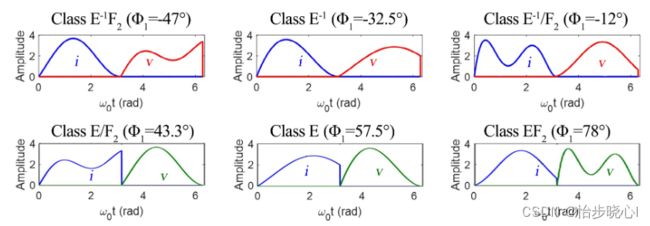
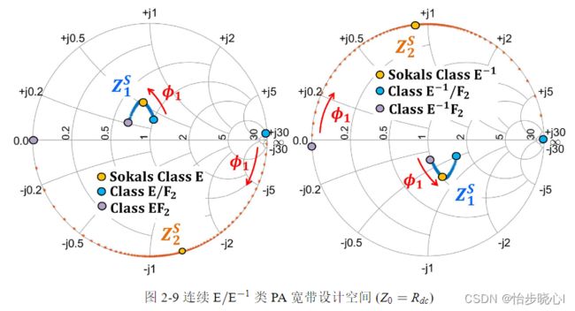
典型的E类PA需要满足ZVS和ZVDS条件以实现100%效率的能量转化。而对于 E − 1 \rm E^{ - 1} E−1类PA,其需要满足ZCS和ZCDS条件以确保其100%效率运行。连续B/J类、连续 F / F − 1 {\rm F/{F^{ - 1}}} F/F−1类通过乘以连续因子以获得更大的宽带设计自由度,而连续 E / E − 1 {\rm E/{E^{ - 1}}} E/E−1类取得宽带阻抗空间的方法与上述不同。具体来说,连续E类PA的求解需要先定义二次谐波的可变负载并假设三次及以上谐波开路,在此基础上结合ZVS与ZVDS条件进行推导。求得的连续E类PA具备一簇波形,其工作模式在EF2、E和E/F3中切换,由此拓展了原始设计的空间。
1.4 带宽拓展的EF与E/F类
Yang, Z., et al. (2020). “A Generalized High-Efficiency Broadband Class-E/F3 Power Amplifier Based on Design Space Expanding of Load Network.” IEEE Transactions on Microwave Theory and Techniques 68(9): 3732-3744.
Liu, C., et al. (2022). “Novel Design Space of Broadband High-Efficiency Parallel-Circuit Class-EF Power Amplifiers.” IEEE Transactions on Circuits and Systems I: Regular Papers 69(9): 3465-3475.
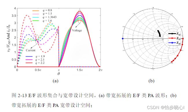
原始的Class-EF与Class-E/F模式不适用于宽带设计。为解决此问题,有学者在电感 L 0 {L_0} L0后串联一个可变无功器件 j X jX jX,在此基础上结合ZVS与ZVDS进行波形的求解,由此可以得到一系列随 X X X变化的高效率波形并拓展其宽带设计空间。

1.5 带宽拓展的X类
Li, X., et al. (2018). “Class-X—Harmonically Tuned Power Amplifiers With Maximally Flat Waveforms Suitable for Over One-Octave Bandwidth Designs.” IEEE Transactions on Microwave Theory and Techniques 66(4): 1939-1950.
Class-X类PA是一种新兴的谐波调谐PA,此类PA基于最大平坦等理想条件求解出的恒定的输出效率表达式。此外,Class-X类PA的二次谐波和三次谐波阻抗可以独立变化,以最大程度地提供宽带设计空间。经过推导,三次谐波调谐下的X类PA理论效率为75%。其宽带阻抗空间求解需要遵寻一定的流程,此处不详细赘述。
