认识LTE(六): LTE中的信道特征以及信道估计技术
认识LTE(六): LTE中的信道特征以及信道估计技术
文章目录
- 认识LTE(六): LTE中的信道特征以及信道估计技术
- 零.代码地址
- 一.LTE中的信道特征
-
- 1.信道的输入输出
- 2.LTE 特征信道模型
- 二.LTE的信道估计流程
-
- 1.LTE中的CSR位置
- 2.利用CSR进行信道估计
- 3.根据CSR插值整个时频信道
- 4.信道响应提取
- 5.题外话:理想信道估计
零.代码地址
https://github.com/liu-zongxi/LTE_simulation
请大家看完觉得有用别忘了点赞收藏,github项目给star哦
一.LTE中的信道特征
1.信道的输入输出
输入x的大小是(nSamp, nTX)
信道的大小是(nSamp, nTX, nRX)
考虑多径则是(nSamp, L, nTX, nRX)
输出的大小是(nSamp, nRX)
2.LTE 特征信道模型
LTE的中信道可调参数
- 多普勒频移:低中高分别对应5,70,300Hz
- 多径时延和功率:看表
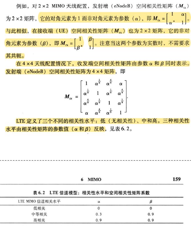
- 相关性:一个特殊形状的矩阵
二.LTE的信道估计流程
1.LTE中的CSR位置
既然要估计信道,首先我们要知道CSR的位置,在多TX中,他是这样的
注意到,四天线的情况下3 4 天线是与众不同的,这在后面的代码中会反复显示出这一点
2.利用CSR进行信道估计
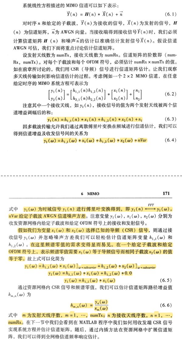
注意到,在MIMO中永远只有一个RE在发送CSR,其他则发送0,被称为频谱零值,为什么呢?
只有这样,才仍然满足简单的除法的信道计算
由此,我们就得到了CSR的估计值
function hD = ChanEstimate_mTx(prmLTE, Rx, Ref, Mode)
%#codegen
% 基本的参数
Nrb           = prmLTE.Nrb;     % Number of resource blocks
Nrb_sc      = prmLTE.Nrb_sc;                 % 12 for normal mode
Ndl_symb = prmLTE.Ndl_symb;        % 7    for normal mode
numTx      = prmLTE.numTx;
numRx      = prmLTE.numRx;
% Initialize output buffer
switch numTx
    % 单天线情况
    case 1                                                                                       % Case of 1 Tx
        % hd的大小和网格是一致的
        hD = complex(zeros(Nrb*Nrb_sc, Ndl_symb*2,numRx));   % Iniitalize Output
        % size(Rx) = [2*Nrb,  4,numRx]  size(Ref) = [2*Nrb, 4]
        % 这个是四个符号的起始值
        % 这是一个RB中CSR的位置前后的空缺,要从下往上看!看我ppt里的图
        Edges=[0,3,0,3];
        for n=1:numRx
            Rec=Rx(:,:,n);
            hp= Rec./Ref;
            % 根据CSR的位置生成全部的频谱了,三种方法都是非常巧妙的,值得学习!
            hD(:,:,n)=gridResponse(hp, Nrb, Nrb_sc, Ndl_symb, Edges,Mode);
        end
    % 两天线
    case 2                                                           % Case of 2 Tx
        % 多一维发射天线
        hD = complex(zeros(Nrb*Nrb_sc, Ndl_symb*2,numTx, numRx));
        % size(Rx) = [4*Nrb,  4,numRx]  size(Ref) = [2*Nrb, 4, numTx]
        for n=1:numRx
            %
            Rec=Rx(:,:,n);
            for m=1:numTx
                % 这个函数从CSR中取出了当前天线的CSR位置
                [R,Edges]=getBoundaries2(m, Rec);
                T=Ref(:,:,m);
                hp= R./T;
                % 得到完整的估计
                hD(:,:,m,n)=gridResponse(hp, Nrb, Nrb_sc, Ndl_symb, Edges,Mode);
            end
        end
    % 四天线
    case 4
        hD = complex(zeros(Nrb*Nrb_sc, Ndl_symb*2,numTx, numRx));
        % size(Rx) = [4*Nrb,  4,numRx]  size(Ref) = [2*Nrb, 4, numTx]
        for n=1:numRx
            Rec=Rx(:,:,n);
            for m=1:numTx
                % 取出当前天线的CSR
                [R,idx3, Edges]=getBoundaries4(m, Rec);
                T=Ref(:,idx3,m);
                hp= R./T;
                % 获得完整的hD
                hD(:,:,m,n)=gridResponse(hp, Nrb, Nrb_sc, Ndl_symb, Edges,Mode);
            end
        end
end
end
%% Helper function
function [R,idx3, Edges]=getBoundaries4(m,  Rec)
coder.varsize('Edges');coder.varsize('idx3');
% 和2是类似的
% idx3也是为了三四天线特殊处理的
numPN=size(Rec,1);
idx_0=(1:2:numPN);
idx_1=(2:2:numPN);
Edges=[0,3,0,3];
idx3=1:4;
switch m
    case 1
        index=[idx_0,  2*numPN+idx_1, 3*numPN+idx_0,  5*numPN+idx_1]';
        Edges=[0,3,0,3];   idx3=1:4;
    case 2
        index=[idx_1,  2*numPN+idx_0, 3*numPN+idx_1,  5*numPN+idx_0]';
        Edges=[3,0,3,0];    idx3=1:4;
    case 3
        index=[numPN+idx_0,  4*numPN+idx_1]';
        Edges=[0,3];           idx3=[1 3];
    case 4
        index=[numPN+idx_1,  4*numPN+idx_0]';
        Edges=[3,0];          idx3=[1 3];
end
R=reshape(Rec(index),numPN/2,numel(Edges));
end
%% Helper function
%
function [R, Edges]=getBoundaries2(m, Rec)
% numPN是一个符号中CSR的个数
% 首先区分出第一个和第二个天线的CSR,因为他是两种拼起来的
numPN=size(Rec,1);
idx_0=(1:2:numPN);
idx_1=(2:2:numPN);
Edges=[0,3,0,3];
switch m
    case 1
        index=[idx_0,  numPN+idx_1, 2*numPN+idx_0, 3*numPN+idx_1]';
        Edges=[0,3,0,3];
    case 2
        index=[idx_1,  numPN+idx_0, 2*numPN+idx_1,  3*numPN+idx_0]';
        Edges=[3,0,3,0];
end
% 取出当前天线的CSR,然后reshape成正确的形状
R=reshape(Rec(index),numPN/2,4);
end
3.根据CSR插值整个时频信道
插值书上提供了三种方法,他们的思路整体是类似的,先把频域插值,然后在时域上填充,三种方法分别使用了不同的手段
- 在有CSR的符号上插值,间隔为6,插值满后以这两个符号为基础,进行加权填充,类似模糊pid中的清晰化
- 在一个时隙内,首先把CSR所在的两个符号交替排列起来,这样插值间隔为3,然后认为时隙上信道不变化,复制
- 在一个子帧上,交替排列再平均,然后认为在子帧上信道不变化,复制
具体代码如下
function hD=gridResponse_averageSlot(hp, Nrb, Nrb_sc, Ndl_symb, Edges)
% Average over the two same Freq subcarriers, and then interpolate between
% them - get all estimates and then repeat over all columns (symbols).
% The interpolation assmues NCellID = 0.
% Time average two pilots over the slots, then interpolate (F)
% between the 4 averaged values, repeat for all symbols in sframe
% 首先把两个拼起来,然后插值
Separation=3;
hD = complex(zeros(Nrb*Nrb_sc, Ndl_symb*2));
N=numel(Edges);
% Compute channel response over all resource elements of OFDM symbols
switch N
    % 四天线34天线特殊情况
    case 2
        % Interpolate between subcarriers
        Index=1:Ndl_symb;
        for n=1:N
            E=Edges(n);Edge=[E, 5-E];
            % 在频域插值
            y = InterpolateCsr(hp(:,n),  2* Separation, Edge);
            % Repeat between OFDM symbols in each slot
            % 复制这一列
            yR=y(:,ones(1,Ndl_symb));
            % 先完成这一时隙
            hD(:,Index)=yR;
            Index=Index+Ndl_symb;
        end
    % 正常情况
    case 4
        Edge=[0 2];
        % 把两个CSR拼起来
        h1_a_mat = [hp(:,1),hp(:,2)].';
        % 非常巧妙,这样一抽就把12一个个交叉起来了,和频域是符合的
        h1_a = h1_a_mat(:);
        % 同理
        h2_a_mat = [hp(:,3),hp(:,4)].';
        h2_a = h2_a_mat(:);
        % 两个拼起来
        hp_a=[h1_a,h2_a];
        Index=1:Ndl_symb;
        for n=1:size(hp_a,2)
            % 插值出频域的
            y = InterpolateCsr(hp_a(:,n),  Separation, Edge);
            % Repeat between OFDM symbols in each slot
            % 复制到每一个plot,也就是还是只有第一列有用
            yR=y(:,ones(1,Ndl_symb));
            hD(:,Index)=yR;
            Index=Index+Ndl_symb;
        end
    otherwise
        error('Wrong Edges parameter for function gridResponse.');
end
function hD=gridResponse_averageSubframe(hp, Ndl_symb, Edges)
% Average over the two same Freq subcarriers, and then interpolate between
% them - get all estimates and then repeat over all columns (symbols).
% The interpolation assmues NCellID = 0.
% Time average two pilots over the slots, then interpolate (F)
% between the 4 averaged values, repeat for all symbols in sframe
Separation=3;
N=numel(Edges);
Edge=[0 2];
% Compute channel response over all resource elements of OFDM symbols
switch N
    % 特殊情况
    case 2
        % 这里是直接把整个子帧交织起来了,非常巧妙,利用了matlab的特性
        h1_a_mat = hp.';
        h1_a = h1_a_mat(:);
        % Interpolate between subcarriers
        % 频域插值
        y = InterpolateCsr(h1_a,  Separation, Edge);
        % Repeat between OFDM symbols
        % 复制
        hD=y(:,ones(1,Ndl_symb*2));
    % 正常情况
    case 4
        % 一样的道理,先平均再交织起来,也是在整个子帧上
        h1_a1 = mean([hp(:, 1), hp(:, 3)],2);
        h1_a2 = mean([hp(:, 2), hp(:, 4)],2);
        h1_a_mat = [h1_a1 h1_a2].';
        h1_a = h1_a_mat(:);
        % Interpolate between subcarriers
        y = InterpolateCsr(h1_a,  Separation, Edge);
        % Repeat between OFDM symbols
        % 复制
        hD=y(:,ones(1,Ndl_symb*2));
    otherwise
        error('Wrong Edges parameter for function gridResponse.');
end
function hD=gridResponse_interpolate(hp, Nrb, Nrb_sc, Ndl_symb, Edges)
% Average over the two same Freq subcarriers, and then interpolate between
% them - get all estimates and then repeat over all columns (symbols).
% The interpolation assmues NCellID = 0.
% Time average two pilots over the slots, then interpolate (F)
% between the 4 averaged values, repeat for all symbols in sframe
%
Separation=6;
hD = complex(zeros(Nrb*Nrb_sc, Ndl_symb*2));
N=numel(Edges);
% Compute channel response over all resource elements of OFDM symbols
switch N
    % 边界为2,这是针对四天线的34天线的
    case 2
        % 所在的符号
        Symbols=[2, 9];
        % Interpolate between subcarriers
        for n=1:N
            % 为什么是5,12中间隔着6然后再加上本身两个CSR
            E=Edges(n);Edge=[E, 5-E];
            % 频域插值
            y = InterpolateCsr(hp(:,n),  Separation, Edge);
            % 得到了CSR的那两列的全频域的信道
            hD(:,Symbols(n))=y;
        end
        % Interpolate between OFDM symbols
        % m是还未被填充的列,即符号
        for m=[1,3:8,10:14]
            % 2,9之间间隔7,加权平均
            % 这应该加绝对值吧。。。
            alpha=(1/7)*(m-2);
            beta=1-alpha;
            hD(:,m)    = beta*hD(:,2) + alpha*hD(:,  9);
        end
    % 有四个起始idx,这是针对正常情况
    case 4
        %  类似的
        Symbols=[1, 5, 8, 12];
        % Interpolate between subcarriers
        for n=1:N
            E=Edges(n);Edge=[E, 5-E];
            y = InterpolateCsr(hp(:,n),  Separation, Edge);
            hD(:,Symbols(n))=y;
        end
        % Interpolate between OFDM symbols
        for m=[2, 3, 4, 6, 7]
            alpha=0.25*(m-1);
            beta=1-alpha;
            hD(:,m)    = beta*hD(:,1) + alpha*hD(:,  5);
            hD(:,m+7) =beta*hD(:,8) + alpha*hD(:,12);
        end
    otherwise
        error('Wrong Edges parameter for function gridResponse.');
end
4.信道响应提取
这一步的意思是我估计了全时频域的信号,现在,要把data对应的信道找出来使用
这就很简单了
function hD=ExtChResponse(chEst, idx_data, prmLTE)
% 这个函数的作用是当你得到全部的hD后,要把CSR等东西都去掉,只留下data的信道
%#codegen
numTx = prmLTE.numTx;
numRx = prmLTE.numRx;
% 取出,再放进去
if (numTx==1)
    hD=complex(zeros(numel(idx_data),numRx));
    for n=1:numRx
        tmp=chEst(:,:,n);
        hD(:,n)=tmp(idx_data);
    end
else
    hD=complex(zeros(numel(idx_data),numTx,numRx));
    for n=1:numRx
        for m=1:numTx
            tmp=chEst(:,:,m,n);
            hD(:,m,n)=tmp(idx_data);
        end
    end
end
5.题外话:理想信道估计
这是利用了matlab算出来的pathG,在时间上平均后放入信道再做FFT得到了,类似我早起博客里OFDM仿真的信道生成
function H = IdChEst(prmLTEPDSCH, prmMdl, chPathG)
% 理想信道估计
% Ideal channel estimation for LTE subframes
%
%   Given the system parameters and the MIMO channel path Gains, provide
%   the ideal channel estimates for the RE corresponding to the data.
%   Limitation - will work for path delays that are multiple of channel sample
%   time and largest pathDelay < size of FFT
%   Implementation based on FFT of channel impulse response
persistent hFFT;
if isempty(hFFT)
   hFFT = dsp.FFT;
end
% get parameters
% 基本参数
numDataTones = prmLTEPDSCH.Nrb*12; % Nrb_sc = 12
N                        = prmLTEPDSCH.N;
cpLen0               = prmLTEPDSCH.cpLen0;
cpLenR               = prmLTEPDSCH.cpLenR;
Ndl_symb           = prmLTE.Ndl_symb;        % 7    for normal mode
slotLen               = (N*Ndl_symb + cpLen0 + cpLenR*6);
% Get path delays
pathDelays = prmMdl.PathDelays;
% Delays, in terms of number of channel samples, +1 for indexing
sampIdx = round(pathDelays/(1/prmLTEPDSCH.chanSRate)) + 1;
% 获得信道的参数
[~, numPaths, numTx, numRx] = size(chPathG);
% Initialize output
% 信道的大小
H = complex(zeros(numDataTones, 2*Ndl_symb, numTx, numRx));
for i= 1:numTx
    for j = 1:numRx
        % 获得当前两天线之间的增益
        link_PathG = chPathG(:, :, i, j);
        % Split this per OFDM symbol
        g = complex(zeros(2*Ndl_symb, numPaths));
        % 先解决1和7的OFDM
        for n = 1:2 % over two slots
            % First OFDM symbol
            Index=(n-1)*slotLen + (1:(N+cpLen0));
            % 得到一个符号时间内的平均增益
            g((n-1)*Ndl_symb+1, :) = mean(link_PathG(Index, :), 1);
            % Next 6 OFDM symbols
            % 其他的OFDM符号
            for k = 1:6
                Index=(n-1)*slotLen+cpLen0+k*N+(k-1)*cpLenR + (1:(N+cpLenR));
                g((n-1)*Ndl_symb+k+1, :) = mean(link_PathG(Index, :), 1);
            end
        end
        % h的时域
        hImp = complex(zeros(2*Ndl_symb, N));
        % assign pathGains at impulse response sample locations
        % 获得时域h
        hImp(:, sampIdx) = g;
        % FFT of impulse response
        h = step(hFFT, hImp.');
        % Reorder, remove DC, Unpack channel gains
        % fftshift
        h = [h(N/2+1:N, :); h(1:N/2, :)];
        % 取出需要的频率
        H(:, :, i, j) = [h(N/2-numDataTones/2+1:N/2, :); h(N/2+2:N/2+1+numDataTones/2, :)];
    end
end


