KITTI坐标变换(KITTI官网推荐)
KITTI Coordinate Transformations
A guide on how to navigate between different sensor coordinate systems of KITTI.

Vipin Sharma
Published in Towards Data Science
5 min read·Jul 7, 2021


(Top) KITTI dataset left RGB camera image. (Bottom) KITTI dataset left RGB camera image with the 3D bounding box (source)
KITTI Dataset Overview
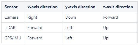
When working on a multi-sensor project, various coordinate frames come into the picture depending upon the sensors used. In the case of the KITTI dataset, there are 3 sensors (camera, LiDAR, and GPS/IMU). The following figure describes the sensor setup of the KITTI dataset.


Figure 1: (Left) KITTI sensor setup. (Right) various involved coordinate frames (source)
There are three different sensors, and hence 3 different coordinate frames involved when working with the KITTI dataset. The figure (above) and table (below) shows the relation between these sensor coordinate frames.
KITTI GT Annotation Details
The ground truth annotations of the KITTI dataset has been provided in the camera coordinate frame (left RGB camera), but to visualize the results on the image plane, or to train a LiDAR only 3D object detection model, it is necessary to understand the different coordinate transformations that come into play when going from one sensor to other. The KITTI GT annotation details have been described in the table below.
GT annotation = (type | truncation | occlusion | alpha | 2D bbox | dimensions | location | score)

Coordinate Transformation Details
KITTI dataset provides camera-image projection matrices for all 4 cameras, a rectification matrix to correct the planar alignment between cameras and transformation matrices for rigid body transformation between different sensors. The figure below shows different projections involved when working with LiDAR data.

Figure 2: KITTI sensor coordinate transformations (by author)
A 3D point x in Velodyne LiDAR coordinates gets projected to a point y in the i’th camera image as:
y = P(i) @ R(0) @ Tvelo_cam @ x

The various transformation of a 3D bounding box from one coordinate frame to another and the steps involved are mentioned below.
Camera-LiDAR 3D bounding-box transformation
The following steps describe the method where the box is first rotated in the camera coordinate frame using yaw-angle and then projected to LiDAR coordinate frame.
- 3D bounding box corner coordinates calculation (camera coordinate frame)

Figure 3: 3D Bounding Box: Camera coordinate system (by author)
x-axis -> right (length), y-axis -> bottom (height), z-axis -> forward (width)
3B bb corner coordinates in camera coordinate frame, coordinate system is at the bottom center of the box.

2. Rotation of the 3D BB corner coordinated by rotation_y angle (camera coordinate frame)
![]()
3. Box translation by centroid coordinates (camera coordinate frame)
![]()
4. 3D BB corner coordinates projection from the camera coordinate to LiDAR coordinate frame
a. Inverse rectification handling R(0)_homo depicts a 4x4 homogenous matrix (without any translation) created from the origin R(0) matrix. The box corners have been transformed from cartesian to homogenous by appending required 0s and 1s.
![]()
b. Inverse rigid body transformation
![]()
LiDAR-Camera 3D bounding-box Transformation
The steps mentioned below defines the procedure of converting a 3D bounding box from LiDAR coordinate frame to camera coordinate frame.
- 3D BB centroid (x, y, z) projection from LiDAR coordinate frame to camera coordinate frame
a. Rigid body transformation
![]()
b. Rectification handling
![]()
2. Heading/yaw angle transformation
Heading/yaw angle is w.r.t z-axis in the LiDAR coordinate frame, which corresponds to -(y-axis) in camera coordinate frame
![]()
3. 3D bounding box corner coordinates calculation (camera coordinate frame)
Figure 4: 3D Bounding Box: Camera coordinate system (by author)
x-axis -> right (length), y-axis -> bottom (height), z-axis -> forward (width)
3B bb corner coordinates in camera coordinate frame, coordinate system is at the bottom center of the box.

4. Rotation of the 3D BB corner coordinated by rotation_y angle (camera coordinate frame)
![]()
5. Box translation by centroid coordinates (camera coordinate frame)
![]()
Camera-Image 3D bounding-box Transformation
The steps mentioned below defines the procedure of converting a 3D bounding box from camera coordinate frame to image coordinate frame.
- Projection of 3D BB corners from camera coordinate frame to image coordinate frame. The box corners have been transformed from cartesian to homogenous by appending required 0s and 1s.
![]()
2. Normalization using z-coordinate
![]()
Conclusion
This article provides a gentle introduction to the KITTI dataset and tries to explain the steps involved in transforming the KITTI GT into various sensor coordinate frames.
Most of the information introduced here has been extracted from the KITTI dataset website and readers are encouraged to go through the cited references for more information.
This blog has also been featured in the KITTI vision Raw Data page: The KITTI Vision Benchmark Suite
References
- Camera-Lidar Projection: Navigating between 2D and 3D
- Vision meets Robotics: The KITTI Dataset — Andreas Geiger
- KITTI Dataset

Written by Vipin Sharma
·Writer for
Towards Data Science
Working in the field of computer vision, learning the complexities of perception one algorithm at a time.