STM32 Cube 发送和接收485数据
1.说明
发送485数据和串口数据是不同的,刚入行一直以为是相同的只是电平的信号可能不同
发送485数据,需要对发送和接收的RE和DE进行使能操作,来决定发送有效,还是接收有效,也就是需要单片机的IO来控制数据的流向!
发送串口数据(TTL), 直接RX和TX反接线即可
这里既然知道了485和串口的区别,那么发送485之前一定要看下电路的原理图是怎么接线的
例如:这里PB0 - DE ,PB1 - RE , PB10 和PB11 接的TX和RX
2.看原理图
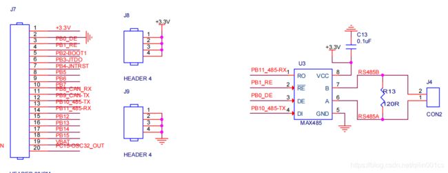
那么我们分析下, 当DE和RE为1时,则发送有效,DE和RE为0时,则接收有效
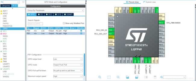
3.单片机引脚配置
串口引脚配置如下:
1.打开UART3 , 设置波特率为:9600,同时打开中断
2.设置GPIO口, GPIOB PIN_0 为低电平,PIN_1为低电平
4. 源码如下:
/**
  ******************************************************************************
  * @file           : main.c
  * @brief          : Main program body
  ******************************************************************************
  * 485串口发送和接收
  *
  ******************************************************************************
  */

#include "main.h"
#include "i2c.h"
#include "usart.h"
#include "gpio.h"
#include "stdio.h"


uint8_t UART1_len=1; //1次只收1个
uint8_t UART1_arr[1]={0};
uint8_t UART1_buf[2]={0};//最大收多少
uint8_t UART1_buf_i=0;


void SystemClock_Config(void);
void send485(uint8_t *pData,uint8_t len);

int main(void)
{

  HAL_Init();
  SystemClock_Config();


  MX_GPIO_Init();
  MX_I2C1_Init();
  MX_USART3_UART_Init();

  HAL_UART_Receive_IT(&huart3, (uint8_t *)UART1_arr, UART1_len);


  while (1)
  {

  }

}

/**
  * @brief System Clock Configuration
  * @retval None
  */
void SystemClock_Config(void)
{
  RCC_OscInitTypeDef RCC_OscInitStruct = {0};
  RCC_ClkInitTypeDef RCC_ClkInitStruct = {0};

  /** Initializes the RCC Oscillators according to the specified parameters
  * in the RCC_OscInitTypeDef structure.
  */
  RCC_OscInitStruct.OscillatorType = RCC_OSCILLATORTYPE_HSI;
  RCC_OscInitStruct.HSIState = RCC_HSI_ON;
  RCC_OscInitStruct.HSICalibrationValue = RCC_HSICALIBRATION_DEFAULT;
  RCC_OscInitStruct.PLL.PLLState = RCC_PLL_ON;
  RCC_OscInitStruct.PLL.PLLSource = RCC_PLLSOURCE_HSI_DIV2;
  RCC_OscInitStruct.PLL.PLLMUL = RCC_PLL_MUL4;
  if (HAL_RCC_OscConfig(&RCC_OscInitStruct) != HAL_OK)
  {
    Error_Handler();
  }
  /** Initializes the CPU, AHB and APB buses clocks
  */
  RCC_ClkInitStruct.ClockType = RCC_CLOCKTYPE_HCLK|RCC_CLOCKTYPE_SYSCLK
                              |RCC_CLOCKTYPE_PCLK1|RCC_CLOCKTYPE_PCLK2;
  RCC_ClkInitStruct.SYSCLKSource = RCC_SYSCLKSOURCE_PLLCLK;
  RCC_ClkInitStruct.AHBCLKDivider = RCC_SYSCLK_DIV1;
  RCC_ClkInitStruct.APB1CLKDivider = RCC_HCLK_DIV1;
  RCC_ClkInitStruct.APB2CLKDivider = RCC_HCLK_DIV1;

  if (HAL_RCC_ClockConfig(&RCC_ClkInitStruct, FLASH_LATENCY_0) != HAL_OK)
  {
    Error_Handler();
  }
}

/* USER CODE BEGIN 4 */
//485发送
void send485(uint8_t *pData,uint8_t len){
	// 485
	//接收:DE为0,RE为0,设置为接收
	//发送:DE为1,RE为 1,设置为发送

	//设置为发送
	HAL_GPIO_WritePin(GPIOB, GPIO_PIN_0, GPIO_PIN_SET); //PB0 = DE = 1
	HAL_GPIO_WritePin(GPIOB, GPIO_PIN_1, GPIO_PIN_SET); //PB1 = RE = 1
	//发送内容
	HAL_UART_Transmit(&huart3, pData, len, 1000);
	//重置为接收
	HAL_GPIO_WritePin(GPIOB, GPIO_PIN_0, GPIO_PIN_RESET); //PB0 = DE = 0
	HAL_GPIO_WritePin(GPIOB, GPIO_PIN_1, GPIO_PIN_RESET); //PB1 = RE = 0
}


//crc modbus485 声明
uint8_t crc16_1 =0;
uint8_t crc16_2 =0;
uint16_t crc_table[] = {
   0x0000, 0xcc01, 0xd801, 0x1400,
   0xf001, 0x3c00, 0x2800, 0xe401,
   0xa001, 0x6c00, 0x7800, 0xb401,
   0x5000, 0x9c01, 0x8801, 0x4400
};
void rs485_crc16(uint8_t *arr,uint8_t len)
{
	uint16_t crc = 0xffff;
	uint8_t	i;
	uint8_t	temp;
   for(i = 0; i < len; i++) {
		temp = *arr++;
		crc = crc_table[(temp ^ crc) & 15] ^ (crc >> 4);
		crc = crc_table[((temp >> 4) ^ crc) & 15] ^ (crc >> 4);
	}
   crc16_1 = (uint8_t)(crc & 0xff ); //高8位
   crc16_2 = (uint8_t)(crc >> 8); //低8位
}


void HAL_UART_RxCpltCallback(UART_HandleTypeDef *huart){
	if(huart->Instance == USART3){ //uart3 端口
		UART1_buf[UART1_buf_i] = UART1_arr[0];
		UART1_buf_i++;
		if(0x0a == UART1_arr[0]){ //检测到结束符 是 0A
			//简单业务逻辑处理
			if(0x01==UART1_buf[0] && 0x0A==UART1_buf[1] ){ //如果发送的是 01 0A 则返回,发送的内容,其他的不返回
				//我们返回485
				uint8_t return_arr[6] = {0x01,0x0A,0x02,0x00,0x00,0x00};
				rs485_crc16(return_arr, 4);
				return_arr[4] = crc16_1;
				return_arr[5] = crc16_2;
				send485((uint8_t *)return_arr,6);
			}
			//i置0
			UART1_buf_i = 0;
		}
		//再次开启打印
		HAL_UART_Receive_IT(&huart3, (uint8_t *)UART1_arr, UART1_len);
	}
}
/* USER CODE END 4 */

/**
  * @brief  This function is executed in case of error occurrence.
  * @retval None
  */
void Error_Handler(void)
{
  /* USER CODE BEGIN Error_Handler_Debug */
  /* User can add his own implementation to report the HAL error return state */
  __disable_irq();
  while (1)
  {
  }
  /* USER CODE END Error_Handler_Debug */
}

#ifdef  USE_FULL_ASSERT
/**
  * @brief  Reports the name of the source file and the source line number
  *         where the assert_param error has occurred.
  * @param  file: pointer to the source file name
  * @param  line: assert_param error line source number
  * @retval None
  */
void assert_failed(uint8_t *file, uint32_t line)
{
  /* USER CODE BEGIN 6 */
  /* User can add his own implementation to report the file name and line number,
     ex: printf("Wrong parameters value: file %s on line %d\r\n", file, line) */
  /* USER CODE END 6 */
}
#endif /* USE_FULL_ASSERT */
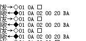
5.演示结果
感谢您的支持,写的文章如对您有所帮助,开源不易,请您打赏,谢谢啦~