OSGEARTH3 绘制点线面
OSGEARTH3 绘制点线面
- 创建点
- 创建面
-
- 地形无关的面
- 绘制一个贴地形的区域
- 创建线
-
- 虚线
- 直线
- 3D图元绘制
-
- 资源
结合OsgEarth3给的例子学习,并进行尝试后,整理的代码

osgEarth的main处初始化,加载绘制图元:
#include void DrawShapeNS::DoDrawTest()
{
// map
osg::Node* globe = osgDB::readNodeFile("../../Data/3d-data/Data/earth/FreeEarth_flat.earth");
osgEarth::MapNode* mapNode = osgEarth::MapNode::get(globe);
// viewer
osgViewer::Viewer viewer;
viewer.setSceneData(mapNode);
/// shape
osg::Group* annoGroup = new osg::Group();
mapNode->addChild(annoGroup);
osg::Group* labelGroup = new osg::Group();
annoGroup->addChild(labelGroup);
osg::ref_ptr<osg::Node> geoRect = DrawRectangle(mapNode->getMapSRS());
annoGroup->addChild(geoRect);
osg::ref_ptr<osg::Node> geoPath = DrawPath(mapNode->getMapSRS());
annoGroup->addChild(geoPath);
osg::ref_ptr<osg::Node> geoCircle = DrawCircle(mapNode->getMapSRS());
annoGroup->addChild(geoCircle);
osg::ref_ptr<osg::Node> geoVolume = DrawVolume(mapNode->getMapSRS());
annoGroup->addChild(geoVolume);
osg::ref_ptr<osg::Node> geoPolygon = DrawPolygon(mapNode->getMapSRS());
annoGroup->addChild(geoPolygon);
osg::ref_ptr<osg::Node> geoRange = DrawRange(mapNode->getMapSRS());
annoGroup->addChild(geoRange);
osg::ref_ptr<osg::Node> geoline = DrawPolyline(mapNode->getMapSRS());
annoGroup->addChild(geoline);
osg::ref_ptr<osg::Node> geoEllipse = DrawEllipse(mapNode->getMapSRS());
annoGroup->addChild(geoEllipse);
// Labels
DrawLabels(mapNode->getMapSRS(), labelGroup);
///
// manipulator
osg::ref_ptr<osgEarth::Util::EarthManipulator> mainManipulator = new osgEarth::Util::EarthManipulator;
viewer.setCameraManipulator(mainManipulator);
// run
viewer.setUpViewInWindow(100, 100, 800, 600);
viewer.run();
}
创建点
创建PlaceNode,其中一个测试了LOD的作用,指定到特定的LOD范围内出现。
void DrawShapeNS::DrawLabels(const osgEarth::SpatialReference* mapSRS, osg::Group* labelGroup)
{
	// Style
	osgEarth::Style pm;
	pm.getOrCreate<osgEarth::IconSymbol>()->url()->setLiteral("../data/placemark32.png");
	pm.getOrCreate<osgEarth::IconSymbol>()->declutter() = true;
	pm.getOrCreate<osgEarth::TextSymbol>()->halo() = osgEarth::Color("#5f5f5f");

	// with lod
	osg::LOD* lod = new osg::LOD();
	lod->addChild(new osgEarth::PlaceNode(osgEarth::GeoPoint(mapSRS, 14.68, 50.0), "Prague_LOD", pm), 0.0, 2e6);
	labelGroup->addChild(lod);
	labelGroup->addChild(new osgEarth::PlaceNode(osgEarth::GeoPoint(mapSRS, 14.68, 50.0), "Prague", pm));

	// absolute altitude:
	labelGroup->addChild(new osgEarth::PlaceNode(osgEarth::GeoPoint(mapSRS, -87.65, 41.90, 1000, osgEarth::ALTMODE_ABSOLUTE), "Chicago", pm));
}
继续向“Prague”该点进行LOD放大,可以看到“Prague_LOD”出现:
创建面
地形无关的面
绘制一个与地形无关的面,由于加载了地形数据,所以面填充在这样的大范围区域看来中间有空洞。
osg::ref_ptr<osg::Node> DrawShapeNS::DrawPolygon(const osgEarth::SpatialReference* mapSRS)
{
	Geometry* geom = new Polygon();
	geom->push_back(osg::Vec3d(0, 40, 0));
	geom->push_back(osg::Vec3d(-60, 40, 0));
	geom->push_back(osg::Vec3d(-60, 60, 0));
	geom->push_back(osg::Vec3d(0, 60, 0));

	Feature* feature = new Feature(geom, mapSRS);
	feature->geoInterp() = GEOINTERP_RHUMB_LINE;

	Style geomStyle;
	geomStyle.getOrCreate<RenderSymbol>()->depthOffset()->enabled() = true;
	geomStyle.getOrCreate<PolygonSymbol>()->fill()->color() = Color(Color::White, 0.8);

	FeatureNode* fnode = new FeatureNode(feature, geomStyle);

	return fnode;
}
绘制一个贴地形的区域
绘制一个贴地形的区域,地形起伏处可以看到面填充与地面贴合(示例在北京范围):主要起作用的Symbol是 osgEarth::AltitudeSymbol,它的osgEarth::AltitudeSymbol::CLAMP_TO_TERRAIN属性。
osg::ref_ptr<osg::Node> DrawShapeNS::DrawRange(const osgEarth::SpatialReference* mapSRS)
{
	Geometry* geom = new Polygon();
	geom->push_back(osg::Vec3d(116.3937806031494, 39.928112175498526, 0));
	geom->push_back(osg::Vec3d(116.39910210583494, 39.92798053678808, 0));
	geom->push_back(osg::Vec3d(116.40047539685057, 39.92337302244748, 0));
	geom->push_back(osg::Vec3d(116.3937806031494, 39.92297807821865, 0));

	Feature* feature = new Feature(geom, mapSRS);
	feature->geoInterp() = GEOINTERP_RHUMB_LINE;

	Style geomStyle;
	geomStyle.getOrCreate<RenderSymbol>()->depthOffset()->enabled() = true;
	geomStyle.getOrCreate<PolygonSymbol>()->fill()->color() = Color(Color::White, 0.8);
	geomStyle.getOrCreate<LineSymbol>()->stroke()->smooth() = true;
	geomStyle.getOrCreate<osgEarth::AltitudeSymbol>()->clamping() = osgEarth::AltitudeSymbol::CLAMP_TO_TERRAIN;
	geomStyle.getOrCreate<osgEarth::AltitudeSymbol>()->technique() = osgEarth::AltitudeSymbol::TECHNIQUE_DRAPE;

	FeatureNode* fnode = new FeatureNode(feature, geomStyle);

	return fnode;
}
创建线
虚线
由于这里设置了Point属性,且设置了tessellationSize,所以每隔7500米会绘制一个点,这样串成一条线(示例指向上海到北京):
osg::ref_ptr<osg::Node> DrawShapeNS::DrawPath(const osgEarth::SpatialReference* mapSRS)
{
	Geometry* path = new LineString();
	path->push_back(osg::Vec3d(116.4039944550781, 40.07433772786638, 0));   // beijing
	path->push_back(osg::Vec3d(121.47006501171873, 31.309586142628824, 0)); // shanghai

	Feature* pathFeature = new Feature(path, mapSRS);
	pathFeature->geoInterp() = GEOINTERP_GREAT_CIRCLE;

	Style pathStyle;
	pathStyle.getOrCreate<LineSymbol>()->stroke()->color() = Color::White;
	pathStyle.getOrCreate<LineSymbol>()->stroke()->width() = 1.0f;
	pathStyle.getOrCreate<LineSymbol>()->stroke()->smooth() = true;
	pathStyle.getOrCreate<LineSymbol>()->tessellationSize()->set(7500, Units::METERS);
	pathStyle.getOrCreate<PointSymbol>()->size() = 8;
	pathStyle.getOrCreate<PointSymbol>()->fill()->color() = Color::Red;
	pathStyle.getOrCreate<PointSymbol>()->smooth() = true;
	pathStyle.getOrCreate<AltitudeSymbol>()->clamping() = AltitudeSymbol::CLAMP_TO_TERRAIN;
	pathStyle.getOrCreate<AltitudeSymbol>()->technique() = AltitudeSymbol::TECHNIQUE_GPU;
	pathStyle.getOrCreate<RenderSymbol>()->depthOffset()->enabled() = true;

	FeatureNode* pathNode = new osgEarth::FeatureNode(pathFeature, pathStyle);

	return pathNode;
}
直线
绘制一条贴地的直线,在地形起伏处可以看到线与地面重合(示例在北京范围),主要设置了geomStyle.getOrCreate()->useGLLines() = true;属性,否则默认是闭合的线。
osg::ref_ptr<osg::Node> DrawShapeNS::DrawPolyline(const osgEarth::SpatialReference* mapSRS)
{
	Geometry* geom = new LineString();
	geom->push_back(osg::Vec3d(116.29910935375975, 39.98600864611971, 0));
	geom->push_back(osg::Vec3d(116.43815506909178, 39.98969130803286, 0));
	geom->push_back(osg::Vec3d(116.48793686840818, 39.95785603053508, 0));
	geom->push_back(osg::Vec3d(116.47866715405272, 39.84275723659836, 0));

	Feature* feature = new Feature(geom, mapSRS);

	Style geomStyle;
	geomStyle.getOrCreate<RenderSymbol>()->depthOffset()->enabled() = true;
	geomStyle.getOrCreate<LineSymbol>()->stroke()->color() = Color::Purple;
	geomStyle.getOrCreate<LineSymbol>()->stroke()->width() = 5.0f;
	geomStyle.getOrCreate<LineSymbol>()->stroke()->smooth() = true;
	geomStyle.getOrCreate<LineSymbol>()->useGLLines() = true;

	geomStyle.getOrCreate<osgEarth::AltitudeSymbol>()->clamping() = osgEarth::AltitudeSymbol::CLAMP_TO_TERRAIN;
	geomStyle.getOrCreate<osgEarth::AltitudeSymbol>()->technique() = osgEarth::AltitudeSymbol::TECHNIQUE_DRAPE;

	FeatureNode* fnode = new FeatureNode(feature, geomStyle);

	return fnode;
}
3D图元绘制
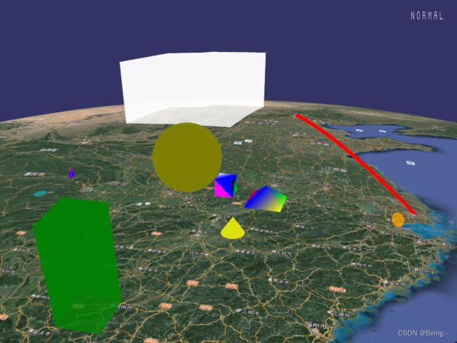
以下是测试OsgEarth3上,在场景内绘制3D图元的测试结果:

资源
直接提供源码的链接吧(本来想介绍Osg+OsgEarth3对于绘制参数的设置,可能没有太多时间,先把资源分享出来)。
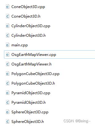
- 封装基于Osg+OsgEarth3实现的3D基础图元类,每个类提供各个图元的基础参数设置。
- 封装的图元类:PolygonCubeObject3D(立方体)、CylinderObject3D(圆柱)、SphereObject3D(球体)、ConeObject3D(圆锥)、PyramidObject3D(四棱锥)。
- OsgEarthMapViewer内包含响应按钮事件(hand函数),以动态修改图元属性的测试。注意测试指定图元属性修改时,需要打开指定handle的注释,并对应switch内的按键进行操作。
- 建议自行建立工程后,编译源码后进行测试(内含main.cpp),随时修改以及时看到变化情况,了解各个参数对绘制的影响。
(相比上面的2D图元绘制的代码,3D图元绘制的资源内,封装了对绘制属性的设置修改,即封装成类,提供到接口操作)
