FPGA-流水灯、呼吸灯
目标:设计一个20Mhz,并且依次点亮4个LED灯的实验
一、流水灯
FPGA实现流水灯主要运用移位操作。想要实现流水灯,就需要使一开始亮的那盏灯进行移位,若其中的LED为共阴极,则当信号为1(高电平)时,LED灯点亮,为0(低电平)时,LED灯熄灭。若假设四个LED灯一开始的电平为 0001 则根据流水灯的设计思路,流水灯的逻辑应该为0001->0010->0100->1000->0001。
(1)50Mhz -> 20Mhz (IP核的创建)
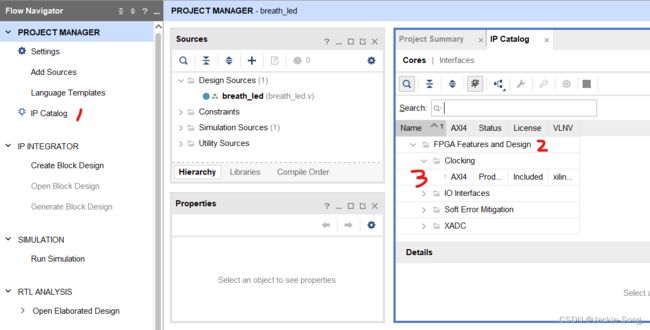
在50Mhz转20Mhz功能实现中,需要用到IP核中的PLL模块。首先打开左边中的IP核,选择FPGA FeaturesDesign,在空白中双击进入。
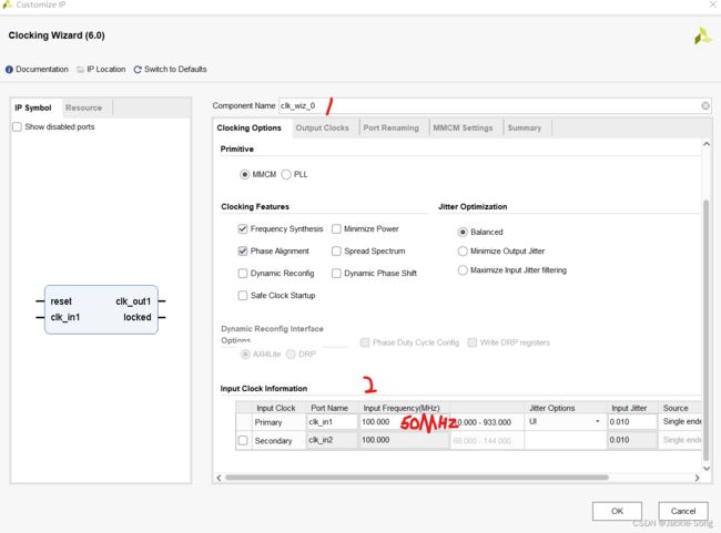
在进入之后会打开如下图的弹窗页面,然后将1处的名字改为PLL(可不改),并将2处的输入频率改为50Mhz,此处改为50Mhz相当于板子上的晶振为50Mhz
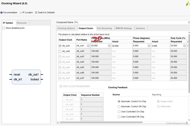
之后在Output Clocks菜单栏中,修改输出的频率,并且将输入的reset1取消掉,点击OK,既将IP核建立成功。详细如下图:
创建成功后需要调用IP核自动生成的函数,因此需要进行函数的查看。
双击PLL.veo
//----------- Begin Cut here for INSTANTIATION Template ---// INST_TAG

  PLL instance_name
   (
    // Clock out ports
    .clk_out1(clk_out1),     // output clk_out1
    // Status and control signals
    .locked(locked),       // output locked
   // Clock in ports
    .clk_in1(clk_in1));      // input clk_in1
// INST_TAG_END ------ End INSTANTIATION Template ---------
该函数为系统生成函数,在进行tb_PLL文件验证时,只需要将其进行复制,修改为自己设置的变量名称即可。下面附上tb_PLL代码块
`timescale 1ns / 1ps

module tb_PLL(

    );

reg clk_in1;


initial begin
    clk_in1=0;
end

always #10 clk_in1=~clk_in1;

PLL inst_PLL(
    // Clock out ports
    .clk_out1(clk_out1),     // output clk_out1
    // Status and control signals
    .locked(locked),       // output locked
   // Clock in ports
    .clk_in1(clk_in1)
    );      // input clk_in1
endmodule
(2)计数器的创建
在进行流水灯设计时,需要将一盏灯点亮之后进行延时,延时工作完毕后,跳转下一盏流水灯亮,因此设计数器在此处充当延时功能。此处代码如下:
module cnt_time(
    input clk,
    input reset,
    output time_en
    );
reg [31:0]cnt_time=0;
parameter COUNT_MAX=31'd19_999_999;

always @(posedge clk) begin
    if (reset) begin
        cnt_time<=1'd0;
    end
    else if (cnt_time==COUNT_MAX) begin
        cnt_time<=1'd0;
    end
    else begin
        cnt_time<=cnt_time+1'd1;
    end
end

assign time_en=(cnt_time==COUNT_MAX)?1'd1:1'd0;

endmodule
(3)流水灯的设计
流水灯设计的核心思想是使用一个移位操作。首先设初始的四盏灯状态分别为1 0 0 0;如果当计数器计满所设定的数值时,该四盏灯进行移位操作,则 led<={led[0],led[3:1]}; 此处的含义为将最后一位移到最前面,将前三位的状态依次往后进行移位。此处代码如下:
//流水灯实验
module water_led(
    input clk,
    input time_en,
    input reset,
    output reg [3:0]led
    );


always @(posedge clk) begin
    if (reset) begin
        led<=4'b1000;
    end
    else if (time_en) begin
        led<={led[0],led[3:1]};
    end
    else begin
        led<=led;
    end
end

endmodule
二、写顶层文件
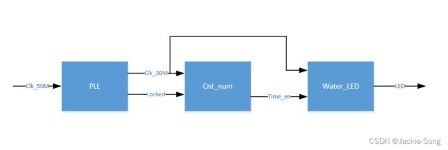
经过IP核、计数器、流水灯三个文件已经写好了完成流水灯的所有模块,但是归根到底,该三个子函数没有进行相互的联系以及相互的串联,因此此处需要top顶层文件将三个子文件进行关联。此处代码如下:
module top_led(
    input clk_in1,
    output [3:0]led
    );

wire clk_out1;
wire locked;
wire time_en;

PLL instance_name(
    // Clock out ports
    .clk_out1(clk_out1),     // output clk_out1
    // Status and control signals
    .locked(locked),       // output locked
   // Clock in ports
    .clk_in1(clk_in1)
    );      // input clk_in1

cnt_time inst_cnt_time(
    .clk        (clk_out1),
    .reset      (~locked),
    .time_en    (time_en)
    );

water_led inst_water_led(
    .clk(clk_out1),
    .time_en    (time_en),
    .reset      (~locked),
    .led        (led)
    );

endmodule
//核心思想是将三个文件的信号源进行相互拼接
注:需要注意reg wire, 避免在编写的时候搞混,以至于仿真无法跑通。
如下为tb_top文件:
//tb_top测试文件
module tb_top(

    );

reg clk_in1;
wire [3:0]led;

initial begin
    clk_in1=0;
end

always #10 clk_in1=~clk_in1;

top_led inst_top_led(
    .clk_in1     (clk_in1),
    .led        (led)
    );

endmodule
三、呼吸灯实验
待补充


