(原创)汽车尾灯电路设计(Digital Logic)(DE2)
Abstract
在DE2上用FSM实现汽车尾灯控制电路。
Introduction
使用环境:Quartus II 9.1 web edition + DE2
假设汽车尾部左右两侧各有3个指示灯,要求设计一个电路实现如下功能:
1. 汽车正常行驶时,尾部两侧的6个灯全灭;
2. 刹车时,尾部两侧的灯全亮,即紧急状态;
3. 右转弯时,右侧3个灯按向右的顺序循环点亮,每次只有一个灯亮,左侧灯全灭;
4. 左转弯时,左侧3个灯按向左的顺序循环点亮,每次只有一个灯亮,右侧灯全灭;
5. 右转弯刹车时,右侧的3个灯顺序循环点亮,左侧的灯全亮;左转弯刹车时,左侧的3个灯顺序循环点亮,右侧的灯全亮;
6. 倒车时,尾部两侧的6个灯不停的按一定频率闪烁。
假设电路的输入钟信号为cp,cp的频率等于汽车尾灯所要求的闪烁频率。Specification
State diagram
1. 输出状态表
| 状态(功能) |
LC LB LA RA RB RC |
| IDLE(6个灯全灭) |
0 0 0 0 0 0 |
| L1(左拐一个灯亮) |
0 0 1 0 0 0 |
| L2 |
0 1 0 0 0 0 |
| L3 |
1 0 0 0 0 0 |
| R1(右拐一个灯亮) |
0 0 0 1 0 0 |
| R2 |
0 0 0 0 1 0 |
| R3 |
0 0 0 1 0 0 |
| FULL(6个灯全亮) |
1 1 1 1 1 1 |
| BL1(左拐刹车) |
0 0 1 1 1 1 |
| BL2 |
0 1 0 1 1 1 |
| BL3 |
1 0 0 1 1 1 |
| BR1(右拐刹车) |
1 1 1 1 0 0 |
| BR2 |
1 1 1 0 1 0 |
| BR3 |
1 1 1 0 0 1 |
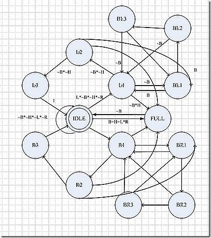
2. 状态图如图 1 汽车尾灯状态图
图 1 汽车尾灯状态图
完成状态图后,这个系统的设计就完成一大部分,剩下的工作就是用HDL描述电路,仿真、下载、验证功能。
完整代码
/*
(C) yf.x 2010 http://halflife.cnblogs.com/
Filename : part1.v
Compiler : Quartus II 9.1 Web Edition
Description : Demo how to use Switch and led
Release : 03/23/2010 1.0
*/
 taillight.v
      //

      tailight.v


      module

       taillight(nrst,haz,left,right,brake,
 lc,lb,la,ra,rb,rc,CLOCK_50);


      input

       haz,left,right,brake;

      //

      warning,turn left,turn right,braking


      input

       nrst,CLOCK_50;


      output

       lc,lb,la,ra,rb,rc;

      //

      6 light


      wire

       lc,lb,la,ra,rb,rc;


      wire

       cp;

      //

      2 HZ


      reg

       [

      19

      :

      0

      ]state,next_state;


      //

      14 states


      parameter

       [

      19

      :

      0

      ]idle

      =

      20

      '

      b00_0000_0000_0001_000_000,


       l1

      =

      20

      '

      b00_0000_0000_0010_001_000,


       l2

      =

      20

      '

      b00_0000_0000_0100_010_000,


       l3

      =

      20

      '

      b00_0000_0000_1000_100_000,


       r1

      =

      20

      '

      b00_0000_0001_0000_000_100,


       r2

      =

      20

      '

      b00_0000_0010_0000_000_010,


       r3

      =

      20

      '

      b00_0000_0100_0000_000_001,


       full

      =

      20

      '

      b00_0000_1000_0000_111_111,


       bl1

      =

      20

      '

      b00_0001_0000_0000_001_111,


       bl2

      =

      20

      '

      b00_0010_0000_0000_010_111,


       bl3

      =

      20

      '

      b00_0100_0000_0000_100_111,


       br1

      =

      20

      '

      b00_1000_0000_0000_111_100,


       br2

      =

      20

      '

      b01_0000_0000_0000_111_010,


       br3

      =

      20

      '

      b10_0000_0000_0000_111_001;


      //

      position of each state


      parameter

       [

      4

      :

      0

      ] idle_pos

      =

      5

      '

      d6,


       l1_pos

      =

      5

      '

      d7,


       l2_pos

      =

      5

      '

      d8,


       l3_pos

      =

      5

      '

      d9,


       r1_pos

      =

      5

      '

      d10,


       r2_pos

      =

      5

      '

      d11,


       r3_pos

      =

      5

      '

      d12,


       full_pos

      =

      5

      '

      d13,


       bl1_pos

      =

      5

      '

      d14,


       bl2_pos

      =

      5

      '

      d15,


       bl3_pos

      =

      5

      '

      d16,


       br1_pos

      =

      5

      '

      d17,


       br2_pos

      =

      5

      '

      d18,


       br3_pos

      =

      5

      '

      d19;


      //

      store status


      always

       @(

      posedge

       cp ,

      negedge

       nrst)


      if

      (

      !

      nrst)
 state

      <=

      idle;


      else


 state

      <=

      next_state;


      //

      state transition ***


      always

       @(haz,left,right,brake)


      begin


 next_state

      =

      idle;


      case

      (

      1

      '

      b1)


       state[idle_pos]:

      if

      (left

      &~

      haz

      &~

      right

      &~

      brake)
 next_state

      =

      l1;


      else


      if

      (right

      &~

      haz

      &~

      left

      &~

      brake)
 next_state

      =

      r1;


      else


      if

      (brake

      |

      haz

      |

      left

      &

      right)
 next_state

      =

      full;


      else


 next_state

      =

      idle;

 state[l1_pos]:

      if

      (brake)
 next_state

      =

      bl1;


      else


      if

      (haz

      &~

      brake)
 next_state

      =

      full;


      else


 next_state

      =

      l2;


 state[l2_pos]:

      if

      (brake)
 next_state

      =

      bl1;


      else


      if

      (haz

      &~

      brake)
 next_state

      =

      full;


      else


 next_state

      =

      l3;

 state[l3_pos]:next_state

      =

      idle;

 state[full_pos]:

      if

      (

      ~

      brake)
 next_state

      =

      idle;


      else


 next_state

      =

      full;

 state[r1_pos]:

      if

      (brake)
 next_state

      =

      br1;


      else


      if

      (haz

      &~

      brake)
 next_state

      =

      full;


      else


 next_state

      =

      r2;

 state[r2_pos]:

      if

      (brake)
 next_state

      =

      br1;


      else


      if

      (haz

      &~

      brake)
 next_state

      =

      full;


      else


 next_state

      =

      r3;

 state[r3_pos]:next_state

      =

      idle;

 state[br1_pos]:

      if

      (

      ~

      brake)
 next_state

      =

      r1;


      //

      else if(~brake&haz)


      //

      next_state=full;


      else


 next_state

      =

      br2;

 state[br2_pos]:

      if

      (

      ~

      brake)
 next_state

      =

      r1;


      //

      else if(~brake&haz)


      //

      next_state=full;


      else


 next_state

      =

      br3;

 state[br3_pos]:

      if

      (

      ~

      brake)
 next_state

      =

      r1;


      else


 next_state

      =

      br1;

 state[bl1_pos]:

      if

      (

      ~

      brake)
 next_state

      =

      l1;


      //

      else if(~brake&haz)


      //

      next_state=full;


      else


 next_state

      =

      bl2;

 state[bl2_pos]:

      if

      (

      ~

      brake)
 next_state

      =

      l1;


      //

      else if(~brake&haz)


      //

      next_state=full;


      else


 next_state

      =

      bl3;

 state[bl3_pos]:

      if

      (

      ~

      brake)
 next_state

      =

      l1;


      else


 next_state

      =

      bl1;


      default

      :next_state

      =

      idle;


      endcase


      end


      //

      output logic


      assign

       la

      =

      state[

      3

      ],
 lb

      =

      state[

      4

      ],
 lc

      =

      state[

      5

      ],
 ra

      =

      state[

      2

      ],
 rb

      =

      state[

      1

      ],
 rc

      =

      state[

      0

      ];


      //

      2hz clock


       divn # (.WIDTH(

      25

      ), .N(

      25000000

      ))
 u0 (
 .clk(CLOCK_50),
 .rst_n(nrst),
 .o_clk(cp)
);


      endmodule
指定
| SW0 |
haz |
| SW1 |
Left |
| SW2 |
Right |
| SW3 |
Brake |
| LEDR[5…0] |
Lc,lb,la,ra,rb,rc |
Conclusion
整个设计最具创意也是最难的部分就是设计状态图,在状态转移描述的部分,我采用了独热码(one-hot code)同时在状态编码的后6位包含输出状态,这样做的优点是简化了译码电路,同时避免毛刺。因为针对DE2上的fpga设计,所以相对占用触发器的资源比其他编码方式要多。但fpga的优点就是触发器资源多。J
目前验证已知存在的问题,汽车尾灯作为一个经典的课设,在John.F wakerly的《数字设计—原理与实践》的第7章有详细的描述,但不包括第5条(转弯时刹车),所以设计状态图,还是不确定足够完美。在DE2上验证时,转弯时刹车必须先转弯(激活转弯的信号)再刹车才会正常显示上述输出状态表的状态。当然这也是刹车的优先级最高决定的,还没发现大问题,但总觉得不够完美,希望有兴趣的同好,能测试一下,看如何改进。
Reference
1. John,F, Wakerly 《数字设计原理与实践(4th)》 机工
2. 罗杰 《Verilog HDL与数字ASIC设计基础》 华科

