Linux下点亮开发板上通过uart外接的led灯
文章目录
- 前言
- 一、pinctrl和gpio子系统
-
- 1.简单介绍
- 2.常用的gpio函数
-
- 1>.gpio_request
- 2>.of_get_named_gpio
- 3>.gpio_free
- 4>.gpio_direction_input
- 5>.gpio_direction_output
- 6>.gpio_get_value
- 7>.gpio_set_value
- 二、修改设备树
-
- 1.查找gpio信息
- 2.修改设备树文件
- 三、相关文件的编写
-
- 1.pinctrl_gpio.c文件
- 2.Makefile文件
- 3.app.c文件
- 四、运行结果
- 总结
前言
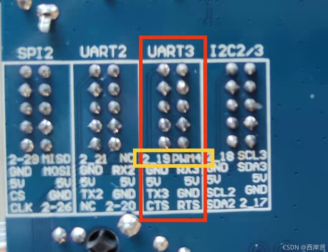
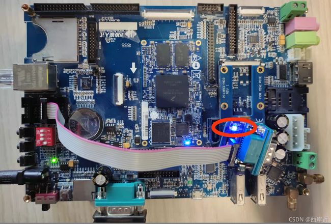
本文是对之前学过的设备树、platform平台总线、pinctrl和gpio子系统及杂项设备驱动的综合练习,其内容是通过程序控制开发板上led的亮灭,这个led是接在uart3上的,贴图如下。

一、pinctrl和gpio子系统
1.简单介绍
按照字面理解,pinctrl是管脚控制,gpio是通用输入输出。
pinctrl子系统的功能:管理系统中所有的可以控制的pin,在系统初始化的时候,枚举所有可以控制的pin,并标识pin;管理pin的复用,对于soc(片上系统)而言,其引脚除了配置成普通的gpio之外,若干个引脚还可以组成一个pin group,形成特定的功能;配置pin的特性。
在路径/linux-4.1.15/Documentation/devicetree/bindings下可以查看gpio、pinctrl等的编写文档。

可以根据自己的需要进到相应的文件下查看。
2.常用的gpio函数
1>.gpio_request
gpio_request的功能是用于申请一个gpio管脚,其在/linux-4.1.15/include/linux/gpio.h文件中的定义如下。
static inline int gpio_request(unsigned gpio, const char *label)
{
	return -ENOSYS;
}
参数介绍:
gpio:要申请的gpio标号,使用of_get_named_gpio函数从设备树获取指定gpio属性信息,该函数会返回这个gpio的标号。
label:给gpio设置一个名称。
返回值:
申请成功时返回0,失败时返回其他值。
2>.of_get_named_gpio
of_get_named_gpio的功能是用于获取gpio编号,其在/linux-4.1.15/include/linux/of_gpio.h文件中的定义如下。
static inline int of_get_named_gpio(struct device_node *np,const char *propname, int index)
{
	return of_get_named_gpio_flags(np, propname, index, NULL);
}
参数介绍:
np:设备节点。
propname:要获取的gpio的名称。
index:一个属性中可能有多个gpio,该参数用来指定要获取其中的哪一个,如果只有一个gpio,该参数设为0即可。
返回值:
成功时返回gpio的编号,失败时返回一个负值。
3>.gpio_free
gpio_free的功能是释放不再使用的gpio,其在/linux-4.1.15/include/linux/gpio.h文件中的定义如下。
static inline void gpio_free(unsigned gpio)
{
	might_sleep();
	/* GPIO can never have been requested */
	WARN_ON(1);
}
参数介绍:
gpio:要释放的gpio标号。
无返回值。
4>.gpio_direction_input
gpio_direction_input的功能是设置某个gpio为输入,其在/linux-4.1.15/include/linux/gpio.h文件中的定义如下。
static inline int gpio_direction_input(unsigned gpio)
{
	return -ENOSYS;
}
参数介绍:
gpio:要设置为输入的gpio标号。
返回值:
设置成功时返回0,设置失败时返回一个负值。
5>.gpio_direction_output
gpio_direction_output的功能是设置某个gpio为输出,同时设置其默认的输出值,其在/linux-4.1.15/include/linux/gpio.h文件中的定义如下。
static inline int gpio_direction_output(unsigned gpio, int value)
{
	return -ENOSYS;
}
参数介绍:
gpio:要设置为输出的gpio标号。
value:gpio的默认输出值。
返回值:
设置成功时返回0,设置失败时返回一个负值。
6>.gpio_get_value
gpio_get_value的功能是获取某个gpio的值(0 or 1),其在/linux-4.1.15/include/linux/gpio.h文件中的定义如下。
static inline int gpio_get_value(unsigned gpio)
{
	/* GPIO can never have been requested or set as {in,out}put */
	WARN_ON(1);
	return 0;
}
参数介绍:
gpio:要获取的gpio标号。
返回值:
成功时返回gpio的值,失败时返回一个负值。
7>.gpio_set_value
gpio_set_value的功能是设置某个gpio的值,其在/linux-4.1.15/include/linux/gpio.h文件中的定义如下。
static inline void gpio_set_value(unsigned gpio, int value)
{
	/* GPIO can never have been requested or set as output */
	WARN_ON(1);
}
参数介绍:
gpio:要设置的gpio标号。
value:要设置的值。
无返回值。
二、修改设备树
设备树的修改和烧写可参见Linux下通过tftp烧写设备树文件并启动开发板。
1.查找gpio信息
查看开发板上连接led的uart的gpio口,我这里用的是uart3。

我的开发板在背面正好有印,可以直接查看,没有的话可以在开发板书册上查询具体的gpio口。
打开/linux-4.1.15/arch/arm/boot/dts/imx6dl-pinfunc.h文件,搜索栏中输入19,查找出自己要的信息。
#define MX6QDL_PAD_EIM_A19__GPIO2_IO19 0x11c 0x4ec 0x000 0x5 0x0
也就是说,开发板上的uart3用的是gpio2的19号引脚。

如上图,这里查找时有好多个和A19相关的复用信息,选择有gpio的那一个就行。
2.修改设备树文件
接着打开我们的设备树文件imx6dl-c-sabresd.dts进行修改。
要添加的代码如下。
test1:test{
		#address-cells = <1>;
		#size-cells = <1>;
		compatible = "test";
		reg = <0x20ac000 0x0000004>;
		pinctrl-names = "default";
        pinctrl-0 = <&pinctrl_led19>;
        uart3-gpio = <&gpio2 19 GPIO_ACTIVE_LOW>;
};

&test1{
	compatible = "test123";
    status = "okay";
};

pinctrl_led19: uart3{  //开发板上uart3对应的gpio
     fsl,pins = <
         MX6QDL_PAD_EIM_A19__GPIO2_IO19     0x80000000
      >;
};
这三段的添加位置如下。

注意上图中这两段之间的括号和分号不要丢掉。

以上这些内容添加完成后保存,打开WSL重新编译设备树并将新的imx6dl-c-sabresd.dtb文件拷贝到tftp目录下,供开发板启动时读取。
三、相关文件的编写
这里文件的编写以Linux中设备树下platform总线的应用和Linux下应用层和内核层的数据传输为基础。
1.pinctrl_gpio.c文件
#include 2.Makefile文件
obj-m += pinctrl_gpio.o
KDIR:=/linux/linux-4.1.15
PWD?=$(shell pwd)
all:
	make -C $(KDIR) M=$(PWD) modules
clean:
	make -C $(KDIR) M=$(PWD) clean
3.app.c文件
#include "stdio.h"
#include "sys/types.h"
#include "sys/stat.h"
#include "fcntl.h"
#include "unistd.h"

int main(int argc, char *argv[])
{
    int fd;
    char buf[64] ={0};
    fd = open("/dev/misc_device", O_RDWR);
    if(fd < 0)
    {
        perror("open error!\n"); //相当于printf("open error!\n");
        return fd;
    }
    buf[0] = atoi(argv[1]); //字符串转换为整型
    write(fd, buf, sizeof(buf));
    /*如果注释掉上面两行代码,用while这段代码的话,app运行之后,led灯就会循环亮灭,每隔一秒切换一下状态*/
   /* while(1){
        buf[0] = 1;
        write(fd, buf, sizeof(buf));
        sleep(1);
        buf[0] = 0;
        write(fd, buf, sizeof(buf));
        sleep(1);
    }*/
    close(fd);
    return 0;
}
四、运行结果
打开开发板启动成功后,将上面的文件编译后产生的驱动文件和经arm编译后的app文件发送至开发板。
先加载驱动,打印信息如下。

因为我们在程序中给gpio的值是1,因此这里加载驱动以后,led就被点亮了,贴图如下。

然后在开发板上通过运行app给gpio赋不同的值,由此来控制led的亮灭。

输入如下命令。
./app 0
./app 1
开发板上的led就又被点亮了。
总结
以上就是Linux下点亮开发板上通过uart外接的led灯的全部内容了,这个例子比较综合,能够将最近学习过的知识都串联起来,这个例子要做到熟稔于心!
本文参考视频:https://www.bilibili.com/video/BV1Vy4y1B7ta?p=29和https://www.bilibili.com/video/BV1Vy4y1B7ta?p=30以及https://www.bilibili.com/video/BV1Vy4y1B7ta?p=31。
