全方位移动机器人 Pure-Pursuit 轨迹跟踪 Gazebo 仿真
全方位移动机器人 Pure-Pursuit 轨迹跟踪 Gazebo 仿真
遗留问题解决
主要是两个问题
1、各个 link 的质量及惯性张量问题
尝试在 SolidWorks 中更改 base_link 的材质,但质量及惯性张量未发生变化,故直接在 URDF 描述文件中调整
总车质量 100 kg,base_link 50 kg,steer_link 10 kg,wheel_link 2.5 kg
<link
    name="base_link">
    <inertial>
      <origin
        xyz="0 0 0"
        rpy="0 0 0" />
      <mass
        value="50.0" />
      <inertia
        ixx="10"
        ixy="0"
        ixz="0"
        iyy="10"
        iyz="0"
        izz="10" />
    inertial>

<link
    name="lf_steer_link">
    <inertial>
      <origin
        xyz="0 0 0"
        rpy="0 0 0" />
      <mass
        value="10" />
      <inertia
        ixx="3"
        ixy="0"
        ixz="0"
        iyy="3"
        iyz="0"
        izz="3" />
    inertial>

<link
    name="lf_wheel_link">
    <inertial>
      <origin
        xyz="0 0 0"
        rpy="0 0 0" />
      <mass
        value="2.5" />
      <inertia
        ixx="1"
        ixy="0"
        ixz="0"
        iyy="1"
        iyz="0"
        izz="1" />
    inertial>
2、base_link 坐标系设置错误
base_link 坐标系设置时没有注意,与其余坐标系冲突,导致手柄控制时与期望运动相差很大
在 SolidWorks 中调整后重新 Export,对比两份 URDF 文件调整后 Rviz 显示坐标系合理

实现过程
首先还是先实现手柄对于仿真移动机器人的控制,此步骤和 Neor_mini 相似
主要包括以下关键环节:
1、修改 URDF 文件,添加 ROS Control Plugin
2、编写 control_mrobot_gazebo.launch 文件
3、编写 gazebo_controllers.yaml 配置文件,调整关节控制器 PID 参数
Gazebo 主要用于仿真移动机器人,包括关节控制器以及位姿信息的发布
Rviz 主要用于显示轨迹跟踪效果,包括参考轨迹以及实际轨迹等
关节控制器 PID 参数如下,基本能够满足控制要求,但仍有较大调整优化空间
control_mrobot:
  joint_state_controller:
    type: joint_state_controller/JointStateController
    publish_rate: 50

 # Velocity Controllers ----速度控制器---------------------
  left_front_wheel_velocity_controller:
    type: effort_controllers/JointVelocityController
    joint: lf_wheel_joint
    pid: {p: 10.0, i: 0.0, d: 0.5}
  right_front_wheel_velocity_controller:
    type: effort_controllers/JointVelocityController
    joint: rf_wheel_joint
    pid: {p: 10.0, i: 0.0, d: 0.5}
  left_back_wheel_velocity_controller:
    type: effort_controllers/JointVelocityController
    joint: lb_wheel_joint
    pid: {p: 10.0, i: 0.0, d: 0.5}
  right_back_wheel_velocity_controller:
    type: effort_controllers/JointVelocityController
    joint: rb_wheel_joint
    pid: {p: 10.0, i: 0.0, d: 0.5}

  # Position Controllers ---位置控制器-----------------------
  left_front_steering_position_controller:
    joint: lf_steer_joint
    type: effort_controllers/JointPositionController
    pid: {p: 15, i: 0.2, d: 5.0}
  right_front_steering_position_controller:
    joint: rf_steer_joint
    type: effort_controllers/JointPositionController
    pid: {p: 15, i: 0.2, d: 5.0}
  left_back_steering_position_controller:
    joint: lb_steer_joint
    type: effort_controllers/JointPositionController
    pid: {p: 15, i: 0.2, d: 5.0}
  right_back_steering_position_controller:
    joint: rb_steer_joint
    type: effort_controllers/JointPositionController
    pid: {p: 15, i: 0.2, d: 5.0}
4、编写 cmd_to_mrobot 功能包,这个和 cmd_to_robot 类似,只是将解算结果直接发布给 Gazebo 中的关节控制器
这里要注意解算结果与关节控制器实际输出的换算
// 注意解算结果与关节控制器实际输出的换算
    vel_left_front_wheel.data = w_params.lf_v / half_tire;
    vel_right_front_wheel.data = w_params.rf_v / half_tire;
    vel_left_back_wheel.data = w_params.lb_v / half_tire;
    vel_right_back_wheel.data = w_params.rb_v / half_tire;
    pos_left_front_steering.data = w_params.lf_p;
    pos_right_front_steering.data = w_params.rf_p;
    pos_left_back_steering.data = w_params.lb_p;
    pos_right_back_steering.data = w_params.rb_p;
5、编写 mrobot_states_update 功能包,主要将 /gazebo/model_states 信息分解为移动机器人位姿和速度信息,再发送出去
int main(int argc, char **argv)
{
    ros::init(argc, argv, "mrobot_states_update");
    ros::NodeHandle nh;

    center_pose_pub = nh.advertise<geometry_msgs::PoseStamped>("/mrobot/center_pose", 1);
    rear_pose_pub = nh.advertise<geometry_msgs::PoseStamped>("/mrobot/rear_pose", 1);
    center_vel_pub = nh.advertise<geometry_msgs::TwistStamped>("/mrobot/center_velocity", 1);

    ros::Subscriber states_sub = nh.subscribe("/gazebo/model_states", 1, states_callback);

    ros::spin();

    return 0;
}
注意四元数到欧拉角的转换,用 Eigen 的话会出现多解跳变,故手写实现
// 计算四元数转换到欧拉角
std::array<float, 3> calQuaternionToEuler(const float x, const float y,
                                          const float z, const float w)
{
    std::array<float, 3> calRPY = {(0, 0, 0)};
    // roll = atan2(2(wx+yz),1-2(x*x+y*y))
    calRPY[0] = atan2(2 * (w * x + y * z), 1 - 2 * (x * x + y * y));
    // pitch = arcsin(2(wy-zx))
    calRPY[1] = asin(2 * (w * y - z * x));
    // yaw = atan2(2(wx+yz),1-2(y*y+z*z))
    calRPY[2] = atan2(2 * (w * z + x * y), 1 - 2 * (y * y + z * z));

    return calRPY;
}
6、修改 purepursui_mod.cpp 文件,主要是订阅话题的修改,在 poseCallback 中实现算法
int main(int argc, char **argv)
{
    // 创建节点
    ros::init(argc, argv, "pure_pursuit");

    // 创建节点句柄
    ros::NodeHandle n;
    // 创建Publisher,发送经过pure_pursuit计算后的转角及速度
    purepersuit_ = n.advertise<geometry_msgs::Twist>("/mrobot/cmd_vel", 20);

    path_pub_ = n.advertise<nav_msgs::Path>("/rvizpath", 100, true);
    // ros::Rate loop_rate(10);

    path.header.frame_id = "world";
    // 设置时间戳
    path.header.stamp = ros::Time::now();
    geometry_msgs::PoseStamped pose;
    pose.header.stamp = ros::Time::now();
    // 设置参考系
    pose.header.frame_id = "world";

    ros::Subscriber splinePath = n.subscribe("/double_lane", 20, pointCallback);
    ros::Subscriber carVel = n.subscribe("/mrobot/center_velocity", 20, velocityCall);
    ros::Subscriber carPose = n.subscribe("/mrobot/rear_pose", 20, poseCallback);
    ros::spin();
    return 0;
}
为了提高 cmd_to_mrobot 中解算代码的通用性,始终为 1.0(前轮转向模式)
// 发布小车运动指令及运动轨迹
    geometry_msgs::Twist vel_msg;
    vel_msg.linear.z = 1.0;
    if (dl <= 0.2) // 离终点很近时停止运动
    {
        vel_msg.linear.x = 0;
        vel_msg.angular.z = 0;
        purepersuit_.publish(vel_msg);
    }
    else
    {
        float theta = atan(2 * Ld * sin(alpha) / dl);
        vel_msg.linear.x = 0.5;
        vel_msg.angular.z = theta;
        purepersuit_.publish(vel_msg);
        // 发布小车运动轨迹
        geometry_msgs::PoseStamped this_pose_stamped;
        this_pose_stamped.pose.position.x = currentPositionX;
        this_pose_stamped.pose.position.y = currentPositionY;

        geometry_msgs::Quaternion goal_quat = tf::createQuaternionMsgFromYaw(theta);
        this_pose_stamped.pose.orientation.x = currentQuaternionX;
        this_pose_stamped.pose.orientation.y = currentQuaternionY;
        this_pose_stamped.pose.orientation.z = currentQuaternionZ;
        this_pose_stamped.pose.orientation.w = currentQuaternionW;

        this_pose_stamped.header.stamp = ros::Time::now();

        this_pose_stamped.header.frame_id = "world";
        path.poses.push_back(this_pose_stamped);
    }

    path_pub_.publish(path);
各个功能包节点间的关系如下

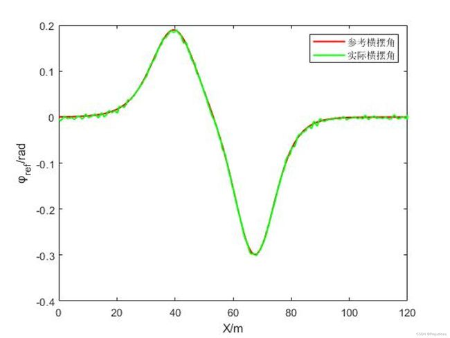
跟踪效果分析
Rviz 中的仿真显示
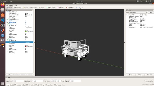
跑了两组数据:
- 2023-11-07-morn0.csv
- 2023-11-07-morn1.csv
预瞄距离 1 m,纵向速度 0.5 m/s
最大横向跟踪误差 0.003466 m,即 3.466 mm;最大横摆角误差 0.005269 rad,即 0.3 度
实际横摆角的抖动可能与 Gazebo 关节控制器的 PID 参数调教有关