fpga时序逻辑(三段式状态机模板、rom实现、边沿检测)
目录
VL21 根据状态转移表实现时序电路
VL22 根据状态转移图实现时序电路
VL23 ROM的简单实现
VL24 边沿检测
VL21 根据状态转移表实现时序电路
题目分析:
1、使用三段式状态机,实现更为方便和简洁。
2、三段式和(一段式、二段式)对比:
优点:
(1)时序逻辑和组合逻辑分开,便于分析。
(2)利于综合软件的分析和优化。
(3)代码简介明了,便于维护。缺点:
(1)代码结构相较两段式复杂。
(2)采用时序逻辑输出避免了亚稳态,但是增加了触发器的使用。数字IC笔面基础,师傅领进门,修行靠个人——人人心中都有一个状态机(状态机简介及Verilog模板)_HFUT90S的博客-CSDN博客
三段式状态机模板:
第1段:描述状态转移(时序逻辑)
第2段:描述状态转移的条件和规律(组合逻辑)
第3段:描述状态输出(组合/时序逻辑)
代码实现:
module seq_circuit(
      input                A   ,
      input                clk ,
      input                rst_n,

      output   wire        Y
);

//三段式状态机

//状态定义
localparam IDLE = 2'b0;    //初态
localparam s0 = 2'b01;
localparam s1 = 2'b10;
localparam s2 = 2'b11;

reg [1:0] CS;	//现态
reg [1:0] NS;	//次态

//描述状态转移(时序逻辑)
always @(posedge clk or negedge rst_n)begin
	if(!rst_n)
		CS <= IDLE;
	else
		CS <= NS;
end

//描述状态转移的条件和规律(组合逻辑)
always @(*)begin
	case(CS)
		IDLE:	if(!A)
					NS = s0;
				else
					NS = s2;
		s0  :	if(!A)
		        	NS = s1;
		        else
		        	NS = IDLE;
		s1  :	if(!A)
		        	NS = s2;
		        else
		        	NS = s0;
        s2  :	if(!A)
		        	NS = IDLE;
		        else
		        	NS = s1;
		default: NS = IDLE;
	endcase
end

//描述状态输出(组合/时序逻辑)
assign Y = ((CS == IDLE)|(CS == s0)|(CS == s1))?0:1;

endmodule
VL22 根据状态转移图实现时序电路
题目分析:
VL22和VL21同理,只不过从状态转移表换成了状态转移图,细心一点就没问题,用的还是三段式状态机。
代码实现:
`timescale 1ns/1ns

module seq_circuit(
   input                C   ,
   input                clk ,
   input                rst_n,

   output   wire        Y
);

//三段式状态机

//状态定义
localparam IDLE = 2'b0;
localparam s0 = 2'b01;
localparam s1 = 2'b10;
localparam s2 = 2'b11;

reg [1:0] CS;	//现态
reg [1:0] NS;	//次态

//描述状态转移(时序逻辑)
always @(posedge clk or negedge rst_n)begin
	if(!rst_n)
		CS <= IDLE;
	else
		CS <= NS;
end

//描述状态转移的条件和规律(组合逻辑)
always @(*)begin
	case(CS)
		IDLE:	if(!C)
					NS = IDLE;	//0
				else
					NS = s0;	//0
		s0  :	if(!C)
		        	NS = s2;	//0
		        else
		        	NS = s0;	//0
		s1  :	if(!C)
		        	NS = IDLE;	//0
		        else
		        	NS = s1;	//1
        s2  :	if(!C)
		        	NS = s2;	//1
		        else
		        	NS = s1;	//1
		default: NS = IDLE;
	endcase
end

//描述状态输出(组合/时序逻辑)
assign Y = ((CS == s2) | ((CS == s1)& (C == 1)))?1:0;

endmodule
VL23 ROM的简单实现
题目描述:
①实现一个深度为8,位宽为4bit的ROM,数据初始化为0,2,4,6,8,10,12,14。可以通过输入地址addr,输出相应的数据data。
②使用Verilog HDL实现以上功能并编写testbench验证。
代码实现:
module VL23_rom(
	input clk,
	input rst_n,
	input [7:0]addr,

	output [3:0]data
);

//定义一个深度为8 宽度为4的数组
reg [3:0] memory [7:0];

always @(posedge clk or negedge rst_n)begin
	if(!rst_n)begin
		memory[0] <= 4'b0;
		memory[1] <= 4'b0;
		memory[2] <= 4'b0;
		memory[3] <= 4'b0;
		memory[4] <= 4'b0;
		memory[5] <= 4'b0;
		memory[6] <= 4'b0;
		memory[7] <= 4'b0;
	end
	else begin
		memory[0] <= 4'd0;
		memory[1] <= 4'd2;
		memory[2] <= 4'd4;
		memory[3] <= 4'd6;
		memory[4] <= 4'd8;
		memory[5] <= 4'd10;
		memory[6] <= 4'd12;
		memory[7] <= 4'd14;
	end
end

assign data = 	(addr == 8'd0)?memory[0]:
				(addr == 8'd1)?memory[1]:
				(addr == 8'd2)?memory[2]:
				(addr == 8'd3)?memory[3]:
				(addr == 8'd4)?memory[4]:
				(addr == 8'd5)?memory[5]:
				(addr == 8'd6)?memory[6]:
				(addr == 8'd7)?memory[7]:0;
endmodule
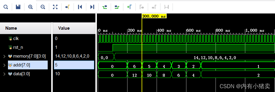
仿真文件:
module tb_VL23_rom;

	// Inputs
	reg clk;
	reg rst_n;
	reg [7:0] addr ;

	// Outputs
	wire [3:0] data;

	// Instantiate the Unit Under Test (UUT)
	VL23_rom uut (
		.clk(clk),
		.rst_n(rst_n),
		.addr(addr),
		.data(data)
	);

	initial begin
		// Initialize Inputs
		clk = 0;
		rst_n = 0;
		addr = 0;

		// Wait 100 ns for global reset to finish
		#100;
		rst_n = 1'b1;

		#100;
		addr = 4'd6;

		#100;						//#100  addr = 4'd5;
		addr = 4'd5;				//代表100ns后addr由上一个状态4'd6 变为此时的状态4'd5

		#100;
		addr = 4'd4;

		#100;
		addr = 4'd3;

		#100;
		addr = 4'd2;

		#100;
		addr = 4'd1;

		// Add stimulus here
	end

	always #10 clk=~clk;

endmodule
仿真图片:
VL24 边沿检测
题目描述:
边沿检测:有一个缓慢变化的1bit信号a,编写一个程序检测a信号的上升沿给出指示信号rise,当a信号出现下降沿时给出指示信号down。
注:rise,down应为单脉冲信号,在相应边沿出现时的下一个时钟为高,之后恢复到0,一直到再一次出现相应的边沿。
代码实现:
module VL24_edge_detect(
	input clk,
	input rst_n,
	input a,

	output reg rise,
	output reg down
);


reg b,c;
wire posedge_flag;
wire negedge_flag;

always @(posedge clk or negedge rst_n)begin
	if(!rst_n)begin
		b <= 1'b0;
		c <= 1'b0;
	end
	else begin
		b <= a;
		c <= b;
	end
end

assign posedge_flag = ~c & b;
assign negedge_flag = c & ~b;

always @(*)begin
	if(posedge_flag)
		rise <= 1'b1;
	else if(negedge_flag)
		down <= 1'b1;
	else begin
		rise <= 1'b0;
		down <= 1'b0;
	end
end

endmodule
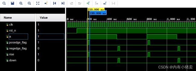
仿真文件:
module tb_VL24_edge_detect;

	// Inputs
	reg clk;
	reg rst_n;
	reg a;

	// Outputs
	wire rise;
	wire down;

	// Instantiate the Unit Under Test (UUT)
	VL24_edge_detect uut (
		.clk(clk),
		.rst_n(rst_n),
		.a(a),

		.rise(rise),
		.down(down)
	);

	initial begin
		// Initialize Inputs
		clk = 0;
		rst_n = 0;
		a = 0;

		// Wait 100 ns for global reset to finish
		#100;
		rst_n = 1'b1;

		#100;
		a = 1;

		#300;
		a = 0;

		#300;
		a = 1;

		#300;
		a = 4'd0;

		// Add stimulus here
	end

	always #10 clk=~clk;

endmodule
仿真图片:
哈哈哈,结束啦!


