防火墙双机热备,基于VRRP实现负载分担双机热备
基于VRRP实现负载分担双机热备
如果要两台FW工作在负载分担模式,两台FW上都要有状态配置为active的VRRP备份组。
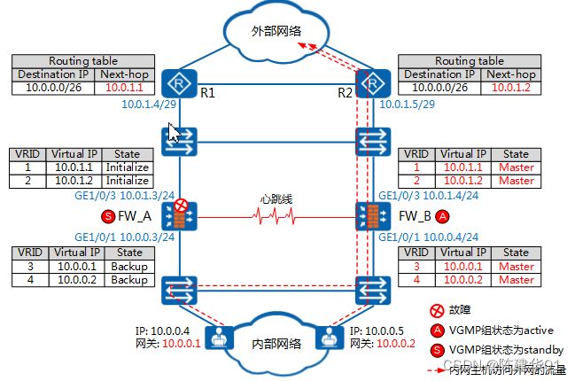
如图1所示,FW_A的VRRP备份组1和3状态被配置成active,VRRP备份组2和4状态被配置成standby。FW_B的VRRP备份组2和4状态被配置成active,VRRP备份组1和3状态被配置成standby。正常情况下,两台设备的VGMP组状态都是load-balance,VRRP备份组的运行状态由配置决定。因此,FW_A的VRRP备份组1和3运行状态是Master,VRRP备份组2和4运行状态是Backup。FW_B的VRRP备份组2和4运行状态都是Master,VRRP备份组1和3运行状态是Backup。
内部网络中部分主机的网关被设置成了VRRP备份组3的虚拟IP地址10.0.0.1。这些主机在访问外部网络时,会广播一个ARP请求报文,请求10.0.0.1的MAC地址。FW_A的VRRP备份组3状态为Master,会响应内网主机的ARP请求。FW_B的VRRP备份组3状态为Backup,不会响应内网主机的ARP请求。FW_A响应的ARP报文会刷新交换机的MAC地址表和主机的ARP缓存表,使这部分主机发往外部网络的流量都被引导到FW_A上处理。
而另一部分主机的网关被设置成了VRRP备份组4的虚拟IP地址10.0.0.2。这些主机在访问外部网络时,同样会广播一个ARP请求报文,请求10.0.0.2的MAC地址。此时,只有FW_B会响应这个ARP请求。因此,这部分主机的流量都被引导到FW_B上转发。
同理,路由器R1到内部网络路由的下一跳地址被设置成了VRRP备份组1的虚拟IP地址10.0.1.1,路由器R1发往内部网络的流量会被引导到FW_A上处理。路由器R2到内部网络路由的下一跳被设置成了VRRP备份组2的虚拟IP地址10.0.1.2,路由器R2发往内部网络的流量会被引导到FW_B上处理。
图1 基于VRRP实现负载分担(双机状态正常)
 如图2所示,FW_A的上行业务接口故障,FW_A的VRRP备份组1和2的状态变为Initialize。同时,FW_A和FW_B的VGMP组状态也发生了变化。FW_A的VGMP组状态变为standby,FW_B的VGMP组状态变为active。FW_A和FW_B基于VGMP组状态对VRRP备份组状态进行调整。FW_A上VRRP备份组3和4的状态被调整为Backup。FW_B上所有VRRP备份组的状态都被调整为Master。
FW_B上VRRP备份组状态由Backup变为Master时会广播免费ARP报文,报文中携带VRRP备份组的虚拟IP地址和接口的MAC地址(开启接口虚MAC地址功能时,携带虚MAC地址)。免费ARP报文会刷新交换机的MAC地址表、主机和路由器的ARP缓存表。这样,内外部网络之间的流量会被引导到FW_B上转发。
同理,如果FW_B发生故障,FW_A无故障,内外部网络之间的流量会被引导到FW_A上转发。
图2 基于VRRP实现负载分担(FW_A故障)
综上所述,正常情况下,FW_A和FW_B都会处理内外部网络之间的流量。FW_A和FW_B之间形成负载分担模式的双机热备。FW_A和FW_B中任意一台故障时,流量都会自动切换到未故障的FW上处理,保证业务不中断。
实验拓扑图
实验步骤
FW1 配置
FW1 防火墙

system-view
Enter system view, return user view with Ctrl+Z.
[USG6000V1]sysname FW1
Nov 17 2023 07:46:03 FW1 DS/4/DATASYNC_CFGCHANGE:OID 1.3.6.1.4.1.2011.5.25.191.3
.1 configurations have been changed. The current change number is 1, the change
loop count is 0, and the maximum number of records is 4095.
[FW1]undo info-center enable
Info: Saving log files...
Info: Information center is disabled.

[FW1]interface GigabitEthernet 1/0/0
[FW1-GigabitEthernet1/0/0]ip address 192.168.1.1 24
[FW1-GigabitEthernet1/0/0]quit

[FW1]interface GigabitEthernet 1/0/6
[FW1-GigabitEthernet1/0/6]ip address 192.168.2.1 24
[FW1-GigabitEthernet1/0/6]quit

[FW1]interface GigabitEthernet 1/0/2
[FW1-GigabitEthernet1/0/2]ip address 172.16.1.1 24
[FW1-GigabitEthernet1/0/2]quit

[FW1]firewall zone trust
[FW1-zone-trust]add interface GigabitEthernet 1/0/0
[FW1-zone-trust]quit

[FW1]firewall zone dmz
[FW1-zone-dmz]add interface GigabitEthernet 1/0/6
[FW1-zone-dmz]quit

[FW1]firewall zone untrust
[FW1-zone-untrust]add interface GigabitEthernet 1/0/2
[FW1-zone-untrust]quit

[FW1]ip route-static 0.0.0.0 0 10.1.1.10

在FW1上行业务接口GE1/0/2上配置VRRP备份组1,并将其状态设置为Active;配置VRRP备份组2,并将其状态设置为Standby

[FW1]interface GigabitEthernet 1/0/2
[FW1-GigabitEthernet1/0/2]vrrp vrid 1 virtual-ip 10.1.1.1 24 active
[FW1-GigabitEthernet1/0/2]vrrp vrid 2 virtual-ip 10.1.1.2 24 standby
[FW1-GigabitEthernet1/0/2]quit

在FW1下行业务接口GE1/0/0上配置VRRP备份组3,并将其状态设置为Active;配置VRRP备份组4,并将其状态设置为Standby

[FW1]interface GigabitEthernet 1/0/0
[FW1-GigabitEthernet1/0/0]vrrp vrid 3 virtual-ip 192.168.1.3 active
[FW1-GigabitEthernet1/0/0]vrrp vrid 4 virtual-ip 192.168.1.4 standby
[FW1-GigabitEthernet1/0/0]quit

[FW1]hrp mirror session enable //负载分担组网下,两台FW都转发流量,为了防止来回路径不一致,需要在两台FW上都配置会话快速备份功能

[FW1]hrp interface GigabitEthernet 1/0/6 remote 192.168.2.2	 //在FW上指定心跳口
[FW1]hrp enable   //启用双机热备功能
Info: NAT IP detect function is disabled.

HRP_M[FW1]security-policy (+B)	//在FW1上配置安全策略。双机热备状态成功建立后,FW1的安全策略配置会自动备份到FW2上
HRP_M[FW1-policy-security]rule name t_to_u (+B)
HRP_M[FW1-policy-security-rule-t_to_u]source-zone trust  (+B)
HRP_M[FW1-policy-security-rule-t_to_u]destination-zone untrust  (+B)
HRP_M[FW1-policy-security-rule-t_to_u]source-address 192.168.1.0 24 (+B)
HRP_M[FW1-policy-security-rule-t_to_u]action permit  (+B)
HRP_M[FW1-policy-security-rule-t_to_u]quit
HRP_M[FW1-policy-security]quit

HRP_M[FW1]nat address-group benet1	//配置NAT地址池
HRP_M[FW1-address-group-benet1]section 0 10.1.1.20 10.1.1.25
HRP_M[FW1-address-group-benet1]quit

HRP_M[FW1]nat-policy  (+B)  //配置NAT策略
HRP_M[FW1-policy-nat]rule name policy_nat1 (+B)
HRP_M[FW1-policy-nat-rule-policy_nat1]source-zone trust  (+B)
HRP_M[FW1-policy-nat-rule-policy_nat1]destination-zone untrust  (+B)
HRP_M[FW1-policy-nat-rule-policy_nat1]source-address 192.168.1.0 16 (+B)
HRP_M[FW1-policy-nat-rule-policy_nat1]action source-nat address-group benet1 (+B
)
HRP_M[FW1-policy-nat-rule-policy_nat1]quit
HRP_M[FW1-policy-nat]quit

HRP_M[FW1]hrp nat resource primary-group  (+B)  //对于双机热备的负载分担组网,为了防止两台设备进行NAT转换时端口冲突,需要在FW_A和FW_B上分别配置可用的端口范围
FW2 配置
FW2 防火墙

system-view
Enter system view, return user view with Ctrl+Z.
[USG6000V1]sysname FW2
Nov 17 2023 07:58:47 FW2 DS/4/DATASYNC_CFGCHANGE:OID 1.3.6.1.4.1.2011.5.25.191.3
.1 configurations have been changed. The current change number is 1, the change
loop count is 0, and the maximum number of records is 4095.
[FW2]undo info-center enable
Info: Saving log files...
Info: Information center is disabled.

[FW2]interface GigabitEthernet 1/0/0
[FW2-GigabitEthernet1/0/0]ip address 192.168.1.2 24
[FW2-GigabitEthernet1/0/0]quit

[FW2]interface GigabitEthernet 1/0/6
[FW2-GigabitEthernet1/0/6]ip address 192.168.2.2 24
[FW2-GigabitEthernet1/0/6]quit

[FW2]interface GigabitEthernet 1/0/2
[FW2-GigabitEthernet1/0/2]ip address 172.16.1.2 24
[FW2-GigabitEthernet1/0/2]quit

[FW2]firewall zone trust
[FW2-zone-trust]add interface GigabitEthernet 1/0/0
[FW2-zone-trust]quit

[FW2]firewall zone dmz
[FW2-zone-dmz]add interface GigabitEthernet 1/0/6
[FW2-zone-dmz]quit

[FW2]firewall zone untrust
[FW2-zone-untrust]add interface GigabitEthernet 1/0/2
[FW2-zone-untrust]quit

[FW2]ip route-static 0.0.0.0 0 10.1.1.10

在FW2上行业务接口GE1/0/2上配置VRRP备份组1,并将其状态设置为Standby;配置VRRP备份组2,并将其状态设置为Active。

[FW2]interface GigabitEthernet 1/0/2
[FW2-GigabitEthernet1/0/2]vrrp vrid 1 virtual-ip 10.1.1.1 24 standby
[FW2-GigabitEthernet1/0/2]vrrp vrid 2 virtual-ip 10.1.1.2 24 active
[FW2-GigabitEthernet1/0/2]quit

在FW2下行业务接口GE1/0/0上配置VRRP备份组3,并将其状态设置为Standby;配置VRRP备份组4,并将其状态设置为Active。

[FW2]interface GigabitEthernet 1/0/0
[FW2-GigabitEthernet1/0/0]vrrp vrid 3 virtual-ip 192.168.1.3 standby
[FW2-GigabitEthernet1/0/0]vrrp vrid 4 virtual-ip 192.168.1.4 active
[FW2-GigabitEthernet1/0/0]quit

[FW2]hrp mirror session enable  //负载分担组网下,两台FW都转发流量,为了防止来回路径不一致,需要在两台FW上都配置会话快速备份功能

[FW2]hrp interface GigabitEthernet 1/0/6 remote 192.168.2.1 //在FW上指定心跳口并启用双机热备功能
[FW2]hrp enable
R1配置
R1 配置

system-view
Enter system view, return user view with Ctrl+Z.
[Huawei]sysname R1

[R1]undo info-center enable
Info: Information center is disabled.

[R1]interface GigabitEthernet 0/0/0
[R1-GigabitEthernet0/0/0]ip address 10.1.1.10 24
[R1-GigabitEthernet0/0/0]quit

[R1]interface LoopBack 0
[R1-LoopBack0]ip address 1.1.1.1 32
[R1-LoopBack0]quit
私网PC1 ping公网R1的loopback已通
FW1防火墙上行接口捉包结果,可看出PC1的包是往FW1防火墙走的
FW2防火墙上行接口捉包结果,可看出PC2的包是往FW2防火墙走的


