实验4.1 静态路由的配置
实验4.1 静态路由的配置
- 一、任务描述
- 二、任务分析
- 三、具体要求
- 四、实验拓扑
- 五、任务实施
-
-
- 1.设置交换机和路由器的基本配置。
- 2.使用display ip interface brief命令查看接口配置信息。
- 3.配置静态路由,实现全网互通。
-
- 六、任务验收
- 七、任务小结
一、任务描述
某公司刚刚成立,规模较小。该公司的网络管理员经过考虑,决定在公司的路由器、交换机与运营商路由器之间使用静态路由,实现网络的互联。
二、任务分析
静态路由一般适用于比较简单的网络环境。在这样的环境中,网络管理员应非常清楚地了解网络的拓扑结构,以便于设置正确的路由信息。由于该网络规模较小且不经常变动,因此使用静态路由比较合适。
三、具体要求
(1)添加3台计算机,将标签分别更改为PC1、PC2和PC3。
(2)添加两台型号为AR2220的路由器,标签名分别为RA和RB,将路由器的名称分别设置为RA和RB。
(3)为RA和RB添加2SA模块,并添加在S 1/0/0接口位置。
(4)添加1台型号为S5700-28C-HI的交换机,标签名为SW3A,将交换机的名称设置为SW3A。
(5)PC1连接SW3A的GE 0/0/1接口,PC2连接SW3A的GE 0/0/2接口,PC3连接RB的GE 0/0/0接口,SW3A的GE 0/0/24接口连接RA的GE 0/0/0接口,RA的S 1/0/0
接口连接RB的S 1/0/0接口。
(6)开启所有交换机和计算机。
(7)路由器和交换机的接口及IP地址等,如下表所示。

(8)根据拓扑图,使用直通线连接好所有计算机。设置每台计算机的IP地址、子网掩码和网关,如下表所示。

(9)在2台路由器和1台交换机之间添加静态路由实现全网互通。
四、实验拓扑

五、任务实施
1.设置交换机和路由器的基本配置。
(1)SW3A的基本配置。
<Huawei>sys
Enter system view, return user view with Ctrl+Z.
[Huawei]sys SW3A
[SW3A]un in e
Info: Information center is disabled.
[SW3A]v b 10 20 100
Info: This operation may take a few seconds. Please wait for a moment...done.
[SW3A]int g0/0/1
[SW3A-GigabitEthernet0/0/1]p l a
[SW3A-GigabitEthernet0/0/1]p d v 10
[SW3A-GigabitEthernet0/0/1]int g0/0/2
[SW3A-GigabitEthernet0/0/2]p l a
[SW3A-GigabitEthernet0/0/2]p d v 20
[SW3A-GigabitEthernet0/0/2]int g0/0/24
[SW3A-GigabitEthernet0/0/24]p l a
[SW3A-GigabitEthernet0/0/24]p d v 100
[SW3A-GigabitEthernet0/0/24]quit
[SW3A]
(2)在SW3A上创建VLANIF接口,在接口视图下配置IP地址。
[SW3A]int vlan 10
[SW3A-Vlanif10]ip add 192.168.10.254 24
[SW3A-Vlanif10]int vlan 20
[SW3A-Vlanif20]ip add 192.168.20.254 24
[SW3A-Vlanif20]int vlan 100
[SW3A-Vlanif100]ip add 192.168.1.1 24
[SW3A-Vlanif100]quit
[SW3A]
(3)RA的基本配置。
<Huawei>sys
Enter system view, return user view with Ctrl+Z.
[Huawei]sys RA
[RA]int g0/0/0
[RA-GigabitEthernet0/0/0]ip add 192.168.1.2 24
Dec  8 2023 09:33:37-08:00 RA %%01IFNET/4/LINK_STATE(l)[0]:The line protocol IP
on the interface GigabitEthernet0/0/0 has entered the UP state.
[RA-GigabitEthernet0/0/0]quit
[RA]int s1/0/0
[RA-Serial1/0/0]ip add 192.168.2.1 24
[RA-Serial1/0/0]quit
[RA]
(4)RB的基本配置。
<Huawei>sys
Enter system view, return user view with Ctrl+Z.
[Huawei]sys RB
[RB]int s1/0/0
[RB-Serial1/0/0]ip add 192.168.2.2 24
[RB-Serial1/0/0]
Dec  8 2023 09:34:40-08:00 RB %%01IFNET/4/LINK_STATE(l)[0]:The line protocol PPP
IPCP on the interface Serial1/0/0 has entered the UP state.
[RB-Serial1/0/0]int g0/0/0
[RB-GigabitEthernet0/0/0]ip add 192.168.30.254 24
Dec  8 2023 09:35:01-08:00 RB %%01IFNET/4/LINK_STATE(l)[1]:The line protocol IP
on the interface GigabitEthernet0/0/0 has entered the UP state.
[RB-GigabitEthernet0/0/0]quit
[RB]
当做好以上配置时可以发现,PC1和PC2之间已经可以互相ping通,不是全网互通。要实现全网互通,需要建立相应的路由表。本实验时通过静态路由来实现全网互通的。
2.使用display ip interface brief命令查看接口配置信息。
[SW3A]display ip interface brief
*down: administratively down
^down: standby
(l): loopback
(s): spoofing
The number of interface that is UP in Physical is 4
The number of interface that is DOWN in Physical is 2
The number of interface that is UP in Protocol is 4
The number of interface that is DOWN in Protocol is 2

Interface                         IP Address/Mask      Physical   Protocol
MEth0/0/1                         unassigned           down       down
NULL0                             unassigned           up         up(s)
Vlanif1                           unassigned           down       down
Vlanif10                          192.168.10.254/24    up         up
Vlanif20                          192.168.20.254/24    up         up
Vlanif100                         192.168.1.1/24       up         up
[SW3A]
3.配置静态路由,实现全网互通。
(1)SW3A不能直接到达的网络都需要添加静态路由,分别有192.168.2.0和192.168.30.0这两个网络,而SW3A到达这两个网络都要通过RA的GE0/0/0接口进行转发,那么GE0/0/0接口的IP的地址就是静态路由的下一跳地址,于是在SW3A上添加的静态路由如下。
[SW3A]ip route-static 192.168.2.0 255.255.255.0 192.168.1.2
[SW3A]ip route-static 192.168.30.0 255.255.255.0 192.168.1.2
(2)RA不能直接到达的网络都需要添加静态路由,分别有192.168.10.0、192.168.20.0、192.168.30.0这三个网络,而RA到达192.168.10.0和192.168.20.0这两个网络都要通过SW3A的GE0/0/24接口进行转发,到达192.168.30.0这个网络要通过RB的Series1/0/0接口,于是在RA上添加的静态路由如下。
[RA]ip route-static 192.168.10.0 255.255.255.0 192.168.1.1
[RA]ip route-static 192.168.20.0 255.255.255.0 192.168.1.1
[RA]ip route-static 192.168.30.0 255.255.255.0 192.168.2.2
(3)RB不能直接到达的网络都需要添加静态路由,分别有192.168.1.0、192.168.10.0、192.168.20.0这三个网络,而RB到达这3个网络都要通过RA的Series1/0/0接口进行转发,那么Series1/0/0接口的IP的地址就是静态路由的下一跳地址,于是在RB上添加的静态路由如下。
[RB]ip route-static 192.168.10.0 255.255.255.0 192.168.2.1
[RB]ip route-static 192.168.20.0 255.255.255.0 192.168.2.1
[RB]ip route-static 192.168.1.0 255.255.255.0 192.168.2.1
六、任务验收
(1)在RA上,使用display ip routing-table命令查看路由表。

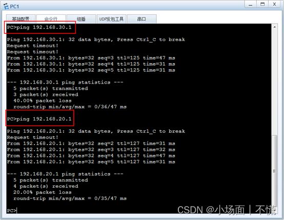
(2)使用PC1测试到PC2和PC3的连通性,可以看到是连通的。
七、任务小结
(1)添加静态路由时对非直连的网段都要进行配置。
(2)在小规模的网络环境中,静态路由是一个不错的选择,但对于大型网络,添加静态路由的工作量就很大。
(3)静态路由开销小,但不灵活,只适用于相对稳定的网络。
注:此为记录笔记,如有不足,还望海涵,可留言斧正