Field Regions 关于近场和阵列面积等效孔径
这里写自定义目录标题
- 2.2.4 Field Regions(Page 33)
- 2.15.2 Antenna Equivalent Areas
本文内容来自天线圣经
2.2.4 Field Regions(Page 33)
D D D is the largest dimension of the antenna. D D D是天线阵最大的物理尺寸。 可以直观地理解为天线阵的最大物理尺寸越大,从天线阵的相隔最远的两个阵元发出的电磁波的差别越大,从而接收端的相位不具有一致性,从而影响远场区。
The space surrounding an antenna is usually subdivided into three regions: (a) reactive near-field, (b) radiating near-field (Fresnel) and © far-field (Fraunhofer) regions as shown in Figure 2.7. These regions are so designated to identify the field structure in each. Although no abrupt changes in the field configurations are noted as the boundaries are crossed, there are distinct differences among them. The boundaries separating these regions are not unique, although various criteria have been established and are commonly used to identify the regions.

Reactive near-field region is defined as “that portion of the near-field region immediately surrounding the antenna wherein the reactive field predominates.” For most antennas, the outer boundary of this region is commonly taken to exist at a distance R < 0.62 D 3 / λ R<0.62 \sqrt{D^{3} / \lambda} R<0.62D3/λ from the antenna surface, where \lambda is the wavelength and D D D is the largest dimension of the antenna. “For a very short dipole, or equivalent radiator, the outer boundary is commonly taken to exist at a distance λ / 2 π \lambda / 2 \pi λ/2π from the antenna surface.”
Radiating near-field (Fresnel) region is defined as “that region of the field of an antenna between the reactive near-field region and the far-field region wherein radiation fields predominate and wherein the angular field distribution is dependent upon the distance from the antenna. If the antenna has a maximum dimension that is not large compared to the wavelength, this region may not exist. For an antenna focused at infinity, the radiating near-field region is sometimes referred to as the Fresnel region on the basis of analogy to optical terminology. If the antenna has a maximum overall dimension which is very small compared to the wavelength, this field region may not exist.” The inner boundary is taken to be the distance R ≥ 0.62 D 3 / λ R \geq 0.62 \sqrt{D^{3} / \lambda} R≥0.62D3/λ and the outer boundary the distance R < 2 D 2 / λ R<2 D^{2} / \lambda R<2D2/λ where D D D is the largest* dimension of the antenna. This criterion is based on a maximum phase error of π / 8 \pi / 8 π/8 . In this region the field pattern is, in general, a function of the radial distance and the radial field component may be appreciable.
To be valid, D D D must also be large compared to the wavelength ( D > λ D > λ D>λ).
Far-field (Fraunhofer) region is defined as "that region of the field of an antenna where the angular field distribution is essentially independent of the distance from the antenna. If the antenna has a maximum † ^{\dagger} † overall dimension D D D , the far-field region is commonly taken to exist at distances greater than 2 D 2 / λ 2 D^{2} / \lambda 2D2/λ from the antenna, \lambda being the wavelength. The far-field patterns of certain antennas, such as multibeam reflector antennas, are sensitive to variations in phase over their apertures. For these antennas 2 D 2 / λ 2 D^{2} / \lambda 2D2/λ may be inadequate. In physical media, if the antenna has a maximum overall dimension, D D D , which is large compared to π / ∣ γ ∣ \pi /|\gamma| π/∣γ∣ , the far-field region can be taken to begin approximately at a distance equal to ∣ γ ∣ D 2 / π |\gamma| D^{2} / \pi ∣γ∣D2/π from the antenna, γ \gamma γ being the propagation constant in the medium. For an antenna focused at infinity, the far-field region is sometimes referred to as the Fraunhofer region on the basis of analogy to optical terminology." In this region, the field components are essentially transverse and the angular distribution is independent of the radial distance where the measurements are made. The inner boundary is taken to be the radial distance R = 2 D 2 / λ R=2 D^{2} / \lambda R=2D2/λ and the outer one at infinity.
The amplitude pattern of an antenna, as the observation distance is varied from the reactive near field to the far field, changes in shape because of variations of the fields, both magnitude and phase. A typical progression of the shape of an antenna, with the largest dimension D D D , is shown in Figure 2.8.It is apparent that in the reactive near-field region the pattern is more spread out and nearly uniform, with slight variations. As the observation is moved to the radiating near-field region (Fresnel), the pattern begins to smooth and form lobes. In the far-field region (Fraunhofer), the pattern is well formed, usually consisting of few minor lobes and one, or more, major lobes.
To illustrate the pattern variation as a function of radial distance beyond the minimum 2 D 2 / λ 2 D^{2} / \lambda 2D2/λ far-field distance, in Figure 2.9 we have included three patterns of a parabolic reflector calculated at distances of R = 2 D 2 / λ , 4 D 2 / λ R=2 D^{2} / \lambda, 4 D^{2} / \lambda R=2D2/λ,4D2/λ , and infinity [4]. It is observed that the patterns are almost identical, except for some differences in the pattern structure around the first null and at a level below 25 d B 25 \mathrm{~dB} 25 dB . Because infinite distances are not realizable in practice, the most commonly used criterion for minimum distance of far-field observations is 2 D 2 / λ 2 D^{2} / \lambda 2D2/λ .

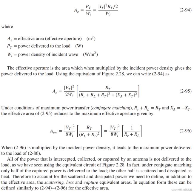
2.15.2 Antenna Equivalent Areas
With each antenna, we can associate a number of equivalent areas. These are used to describe the power capturing characteristics of the antenna when a wave impinges on it. One of these equivalent areas is the effective area (aperture), which in a given direction is defined as “the ratio of the available power at the terminals of a receiving antenna to the power flux density of a plane wave incident on the antenna from that direction, the wave being polarization-matched to the antenna. If the direction is not specified, the direction of maximum radiation intensity is implied.” In equation form it is written as
对于每个天线,我们可以关联一些等价的区域。这些被用来描述当波冲击天线时天线的功率捕获特性。这些等效区域之一是有效区域(孔径),在一个给定的方向被定义为“接收天线的终端可用功率与天线的功率通量密度的比例,波被天线匹配。如果没有指定辐射方向,则暗示了最大辐射强度的方向。”用方程的形式写成