几个信号与系统常用函数的傅里叶变换(用python绘制)
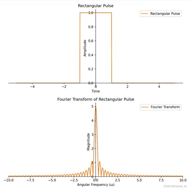
1.门函数
![]()
当![]() =1时,python代码如下:
=1时,python代码如下:
import numpy as np
import matplotlib.pyplot as plt

# 定义门函数(矩形波)函数
def rect(t, a):
    return np.where(np.abs(t) <= a / 2, 1, 0)

# 定义傅里叶变换函数
def FourierTransform(x, t):
    N = len(x)
    dt = t[1] - t[0]
    omega = (2 * np.pi / (N * dt)) * np.fft.fftshift(np.fft.fftfreq(N, dt))
    X = dt * np.sqrt(2 * np.pi) * np.fft.fftshift(np.fft.fft(x))
    return omega, X

# 配置绘图参数
t = np.linspace(-5, 5, 1000)  # 时间轴范围
a = 2  # 门函数的宽度
x = rect(t, a)  # 计算门函数的值
omega, X = FourierTransform(x, t)  # 计算傅里叶变换

# 绘制门函数和傅里叶变换图像
fig, (ax1, ax2) = plt.subplots(2, 1, figsize=(8, 8))

ax1.plot(t, x)  # 绘制门函数曲线
ax1.set_xlabel('Time')  # 设置x轴标签
ax1.set_ylabel('Amplitude')  # 设置y轴标签
ax1.set_title('Rectangular Pulse')  # 设置标题

ax2.plot(omega, np.abs(X))  # 绘制傅里叶变换曲线
ax2.set_xlim(-10, 10)  # 设置x轴范围
ax2.set_xlabel('Angular Frequency (ω)')  # 设置x轴标签
ax2.set_ylabel('Magnitude')  # 设置y轴标签
ax2.set_title('Fourier Transform of Rectangular Pulse')  # 设置标题

# 将坐标轴放在图像中间
# 配置第一个子图的坐标轴
ax1.spines['left'].set_position('center')
ax1.spines['bottom'].set_position('zero')
ax1.spines['right'].set_color('none')
ax1.spines['top'].set_color('none')
ax1.xaxis.set_ticks_position('bottom')
ax1.yaxis.set_ticks_position('left')

# 配置第二个子图的坐标轴
ax2.spines['left'].set_position('center')
ax2.spines['bottom'].set_position('zero')
ax2.spines['right'].set_color('none')
ax2.spines['top'].set_color('none')
ax2.xaxis.set_ticks_position('bottom')
ax2.yaxis.set_ticks_position('left')

# 显示原函数和傅里叶变换函数曲线
ax1.plot(t, x, label='Rectangular Pulse')  # 在第一个子图中绘制原函数曲线
ax2.plot(omega, np.abs(X), label='Fourier Transform')  # 在第二个子图中绘制傅里叶变换函数曲线
ax1.legend()  # 显示原函数曲线的图例
ax2.legend()  # 显示傅里叶变换函数曲线的图例

plt.tight_layout()  # 调整图像布局
plt.show() # 显示图像2.阶跃函数
![]()
代码如下:
import numpy as np
import matplotlib.pyplot as plt

# 定义阶跃函数
def step(t):
    return np.where(t >= 0, 1, 0)

# 定义傅里叶变换函数
def FourierTransform(x, t):
    N = len(x)
    dt = t[1] - t[0]
    df = 1. / (N * dt)
    w = 2 * np.pi * df * np.arange(-N//2, N//2)
    X = dt * np.sqrt(2 * np.pi) * np.fft.fftshift(np.fft.fft(x)) / df
    return w, X

# 配置绘图参数
t = np.linspace(-10, 10, 1000)  # 时间轴范围
x = step(t)  # 计算阶跃函数的值
w, X = FourierTransform(x, t)  # 计算傅里叶变换

# 绘制阶跃函数和傅里叶变换图像
fig, (ax1, ax2) = plt.subplots(2, 1, figsize=(8, 8))

ax1.plot(t, x)  # 绘制阶跃函数曲线
ax1.set_xlabel('Time')  # 设置x轴标签
ax1.set_ylabel('Amplitude')  # 设置y轴标签
ax1.set_title('Unit Step Function')  # 设置标题

ax2.plot(w, np.abs(X))  # 绘制傅里叶变换曲线
ax2.set_xlim(-10, 10)  # 设置x轴范围
ax2.set_xlabel('Frequency (ω)')  # 设置x轴标签
ax2.set_ylabel('Magnitude')  # 设置y轴标签
ax2.set_title('Fourier Transform of Unit Step Function')  # 设置标题

# 将坐标轴放在图像中间
# 配置第一个子图的坐标轴
ax1.spines['left'].set_position('center')
ax1.spines['bottom'].set_position('zero')
ax1.spines['right'].set_color('none')
ax1.spines['top'].set_color('none')
ax1.xaxis.set_ticks_position('bottom')
ax1.yaxis.set_ticks_position('left')

# 配置第二个子图的坐标轴
ax2.spines['left'].set_position('center')
ax2.spines['bottom'].set_position('zero')
ax2.spines['right'].set_color('none')
ax2.spines['top'].set_color('none')
ax2.xaxis.set_ticks_position('bottom')
ax2.yaxis.set_ticks_position('left')

# 显示阶跃函数和傅里叶变换函数曲线
ax1.plot(t, x, label='Unit Step Function')  # 在第一个子图中绘制阶跃函数曲线
ax2.plot(w, np.abs(X), label='Fourier Transform')  # 在第二个子图中绘制傅里叶变换曲线

ax1.legend()  # 在第一个子图中显示图例
ax2.legend()  # 在第二个子图中显示图例

# 显示图像
plt.show()
图像如下:
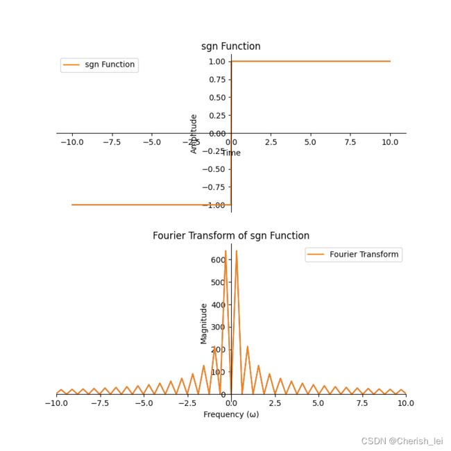
3.sgn函数
![]()
代码如下:
import numpy as np
import matplotlib.pyplot as plt

# 定义 sgn 函数
def sgn(t):
    return np.where(t < 0, -1, np.where(t > 0, 1, 0))

# 定义傅里叶变换函数
def FourierTransform(x, t):
    N = len(x)
    dt = t[1] - t[0]
    df = 1. / (N * dt)
    w = 2 * np.pi * df * np.arange(-N//2, N//2)
    X = dt * np.sqrt(2 * np.pi) * np.fft.fftshift(np.fft.fft(x)) / df
    return w, X

# 配置绘图参数
t = np.linspace(-10, 10, 1000)  # 时间轴范围
x = sgn(t)  # 计算 sgn 函数的值
w, X = FourierTransform(x, t)  # 计算傅里叶变换

# 绘制 sgn 函数和傅里叶变换图像
fig, (ax1, ax2) = plt.subplots(2, 1, figsize=(8, 8))

ax1.plot(t, x)  # 绘制 sgn 函数曲线
ax1.set_xlabel('Time')  # 设置 x 轴标签
ax1.set_ylabel('Amplitude')  # 设置 y 轴标签
ax1.set_title('sgn Function')  # 设置标题

ax2.plot(w, np.abs(X))  # 绘制傅里叶变换曲线
ax2.set_xlim(-10, 10)  # 设置 x 轴范围
ax2.set_xlabel('Frequency (ω)')  # 设置 x 轴标签
ax2.set_ylabel('Magnitude')  # 设置 y 轴标签
ax2.set_title('Fourier Transform of sgn Function')  # 设置标题

# 将坐标轴放在图像中间
# 配置第一个子图的坐标轴
ax1.spines['left'].set_position('center')
ax1.spines['bottom'].set_position('zero')
ax1.spines['right'].set_color('none')
ax1.spines['top'].set_color('none')
ax1.xaxis.set_ticks_position('bottom')
ax1.yaxis.set_ticks_position('left')

# 配置第二个子图的坐标轴
ax2.spines['left'].set_position('center')
ax2.spines['bottom'].set_position('zero')
ax2.spines['right'].set_color('none')
ax2.spines['top'].set_color('none')
ax2.xaxis.set_ticks_position('bottom')
ax2.yaxis.set_ticks_position('left')

# 显示 sgn 函数和傅里叶变换函数曲线
ax1.plot(t, x, label='sgn Function')  # 在第一个子图中绘制 sgn 函数曲线
ax2.plot(w, np.abs(X), label='Fourier Transform')  # 在第二个子图中绘制傅里叶变换曲线

ax1.legend()  # 在第一个子图中显示图例
ax2.legend()  # 在第二个子图中显示图例

# 显示图像
plt.show()4.余弦函数
![]()
代码如下:
import numpy as np
import matplotlib.pyplot as plt

# 定义余弦函数
def cosine(t, w):
    return np.cos(w * t)

# 定义傅里叶变换函数
def FourierTransform(x, t):
    N = len(x)
    dt = t[1] - t[0]
    df = 1. / (N * dt)
    w = 2 * np.pi * df * np.arange(-N//2, N//2)
    X = dt * np.sqrt(2 * np.pi) * np.fft.fftshift(np.fft.fft(x)) / df
    return w, X

# 配置绘图参数
t = np.linspace(-10, 10, 1000)  # 时间轴范围
w = 1  # 频率
x = cosine(t, w)  # 计算余弦函数的值
w, X = FourierTransform(x, t)  # 计算傅里叶变换

# 绘制余弦函数和傅里叶变换图像
fig, (ax1, ax2) = plt.subplots(2, 1, figsize=(8, 8))

ax1.plot(t, x)  # 绘制余弦函数曲线
ax1.set_xlabel('Time')  # 设置 x 轴标签
ax1.set_ylabel('Amplitude')  # 设置 y 轴标签
ax1.set_title('Cosine Function')  # 设置标题

ax2.plot(w, np.abs(X))  # 绘制傅里叶变换曲线
ax2.set_xlim(-10, 10)  # 设置 x 轴范围
ax2.set_xlabel('Frequency (w)')  # 设置 x 轴标签
ax2.set_ylabel('Magnitude')  # 设置 y 轴标签
ax2.set_title('Fourier Transform of Cosine Function')  # 设置标题

# 将坐标轴放在图像中间
# 配置第一个子图的坐标轴
ax1.spines['left'].set_position('center')
ax1.spines['bottom'].set_position('zero')
ax1.spines['right'].set_color('none')
ax1.spines['top'].set_color('none')
ax1.xaxis.set_ticks_position('bottom')
ax1.yaxis.set_ticks_position('left')

# 配置第二个子图的坐标轴
ax2.spines['left'].set_position('center')
ax2.spines['bottom'].set_position('zero')
ax2.spines['right'].set_color('none')
ax2.spines['top'].set_color('none')
ax2.xaxis.set_ticks_position('bottom')
ax2.yaxis.set_ticks_position('left')

# 显示余弦函数和傅里叶变换函数曲线
ax1.plot(t, x, label='Cosine Function')  # 在第一个子图中绘制余弦函数曲线
ax2.plot(w, np.abs(X), label='Fourier Transform')  # 在第二个子图中绘制傅里叶变换曲线

ax1.legend()  # 在第一个子图中显示图例
ax2.legend()  # 在第二个子图中显示图例

# 显示图像
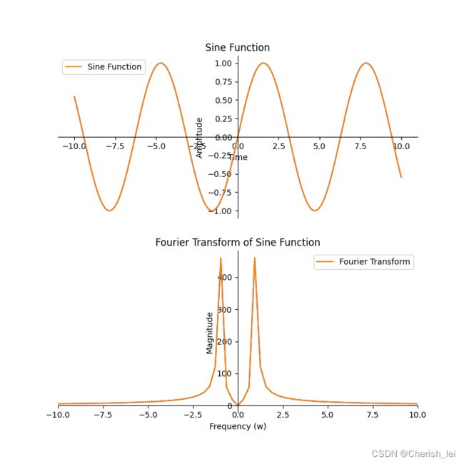
plt.show()5.正弦函数
![]()
代码如下:
import numpy as np
import matplotlib.pyplot as plt

# 定义正弦函数
def sine(t, w):
    return np.sin(w * t)

# 定义傅里叶变换函数
def FourierTransform(x, t):
    N = len(x)
    dt = t[1] - t[0]
    df = 1. / (N * dt)
    w = 2 * np.pi * df * np.arange(-N//2, N//2)
    X = dt * np.sqrt(2 * np.pi) * np.fft.fftshift(np.fft.fft(x)) / df
    return w, X

# 配置绘图参数
t = np.linspace(-10, 10, 1000)  # 时间轴范围
w = 1  # 频率
x = sine(t, w)  # 计算正弦函数的值
w, X = FourierTransform(x, t)  # 计算傅里叶变换

# 绘制正弦函数和傅里叶变换图像
fig, (ax1, ax2) = plt.subplots(2, 1, figsize=(8, 8))

ax1.plot(t, x)  # 绘制正弦函数曲线
ax1.set_xlabel('Time')  # 设置 x 轴标签
ax1.set_ylabel('Amplitude')  # 设置 y 轴标签
ax1.set_title('Sine Function')  # 设置标题

ax2.plot(w, np.abs(X))  # 绘制傅里叶变换曲线
ax2.set_xlim(-10, 10)  # 设置 x 轴范围
ax2.set_xlabel('Frequency (w)')  # 设置 x 轴标签
ax2.set_ylabel('Magnitude')  # 设置 y 轴标签
ax2.set_title('Fourier Transform of Sine Function')  # 设置标题

# 将坐标轴放在图像中间
# 配置第一个子图的坐标轴
ax1.spines['left'].set_position('center')
ax1.spines['bottom'].set_position('zero')
ax1.spines['right'].set_color('none')
ax1.spines['top'].set_color('none')
ax1.xaxis.set_ticks_position('bottom')
ax1.yaxis.set_ticks_position('left')

# 配置第二个子图的坐标轴
ax2.spines['left'].set_position('center')
ax2.spines['bottom'].set_position('zero')
ax2.spines['right'].set_color('none')
ax2.spines['top'].set_color('none')
ax2.xaxis.set_ticks_position('bottom')
ax2.yaxis.set_ticks_position('left')

# 显示正弦函数和傅里叶变换函数曲线
ax1.plot(t, x, label='Sine Function')  # 在第一个子图中绘制正弦函数曲线
ax2.plot(w, np.abs(X), label='Fourier Transform')  # 在第二个子图中绘制傅里叶变换曲线

ax1.legend()  # 在第一个子图中显示图例
ax2.legend()  # 在第二个子图中显示图例

# 显示图像
plt.show()


