STM32L432+LIS3DH【加速度传感器】:端侧AI
一、搜集芯片资料
1.LIS3DHTR:加速度传感器
查找链接:
https://www.st.com/zh/mems-and-sensors/lis3dh.html
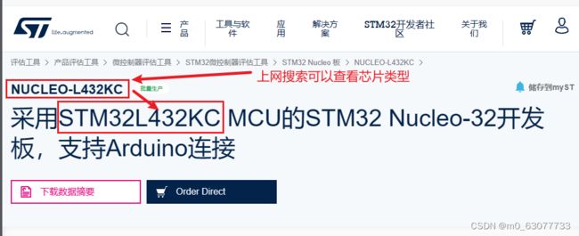
2. NUCLEO-L432KC:芯片
查找连接:
https://www.st.com/zh/evaluation-tools/nucleo-l432kc.html#cad-resources
1.原理图
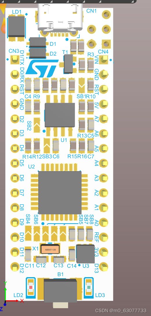
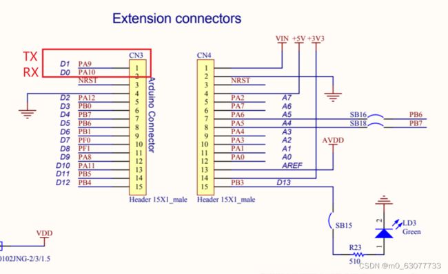
引脚定义
2.芯片图
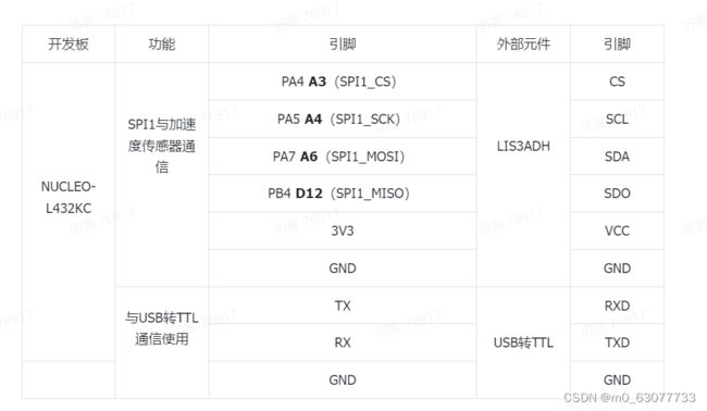
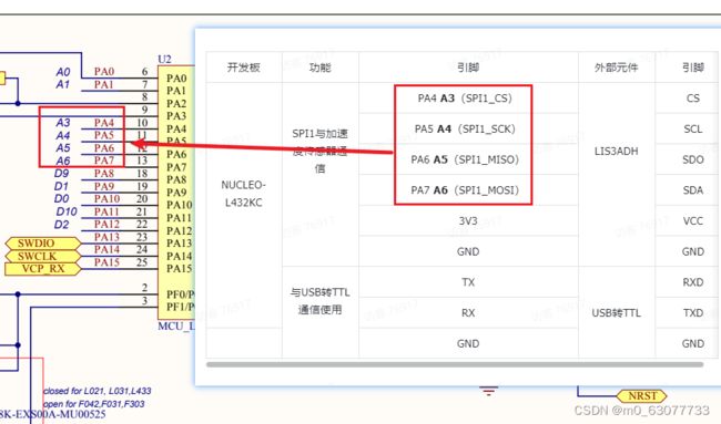
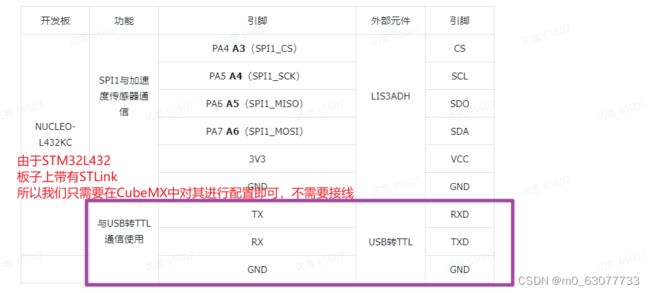
开发板和外设之间通信需要使用到引脚
二、三轴传感器:LIS3DHTR
三轴传感器:只有加速度
六轴传感器:MPU6050【加速度+陀螺仪】
九轴传感器:【磁力计+加速度+陀螺仪】
1.芯片内部的基本功能描述
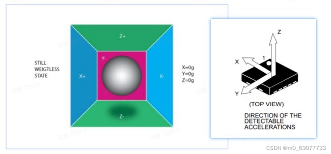
1.加速度
比如跑步2m/s,我在1s后的速度3m/s,这个时候我的加速度就是1m/s,我此时的加速度是1m每平方秒,(1m/s)/s=1m每平方秒。
单位:g(重力 9.8米每平方秒)
当我们把【LIS3DHTR】正放在桌面上,看似z轴方向上是没有再变化的,实际上z轴上面有一个固定的值。【不为零--->因为受到地球重力】
当静止不动的时候,默认是没有动的。
2.陀螺仪:计算角速度
3.磁力计
磁力计指针会固定指向一个方向
为什么要一直旋转??因为会容易受到干扰,所以需要转动进行校准。
手机的横屏,竖屏
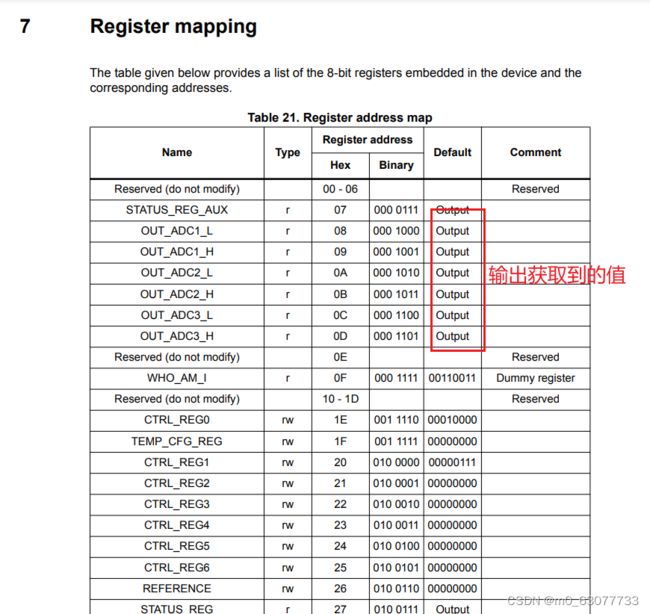
2.LIS3DH的重要寄存器
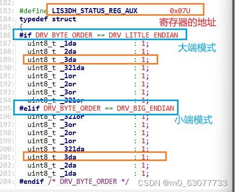
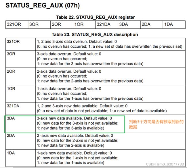
1.STATUS_REG_AUX
2.WHO_AM_I
每一个厂商的ID值是不同的
![]()
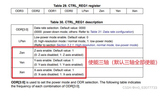
3.CTRL_REG1
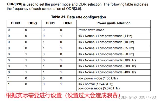
如果要设置为低功耗模式,则再待机的时候就将不需要的修改为0。
采样率:要看具体的使用场景,要尽量选高一点,采样出来的结果才会比较接近,但是也要保持精度。但是还是要靠近实际需求。
4.CTRL_REG4
满量程选择:查看这个芯片可以承受的数据范围
3.LIS3DH芯片数据手册
主要:特征,芯片引脚,寄存器,量程(电压,电流的范围)
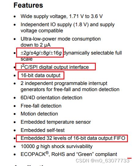
1.芯片基本特征
这个芯片是16bit的数据输出位。如果我们设置量程是8g(记得有正负)
如果我们设置量程是16g(记得有正负)---》这个结果相当于1g的测量范围(比8g的大)--》所以精确度变低了
量程越大,所计算出来的精确度越低。
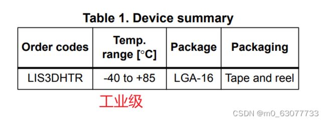
2.温度适应范围
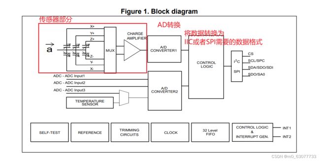
3.块状图
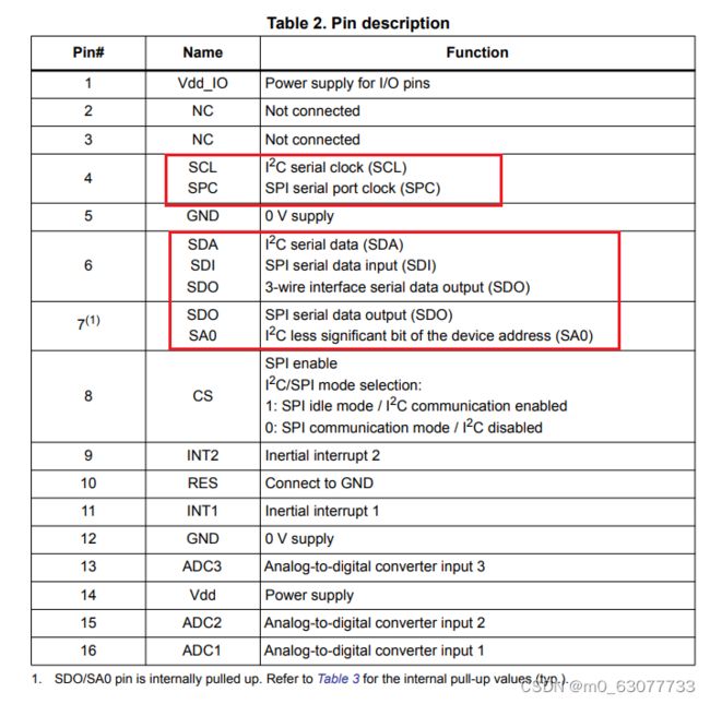
4.引脚描述
1)注意不要把芯片方向装反了(方向很重要)
NC:没有封装【公模】
RES:保留引脚【一般默认接地--》这样对芯片移植没有影响】
CS:片选(判断是选中哪一个芯片)---》SPI使用的
IN1,IN2:中断
5.机器性能
量程选择,机械特性
6.供电范围
![]()
7.寄存器映射
4.SPI
LIS3DH支持IIC和SPI
1.IIC和SPI对比
需要几条线
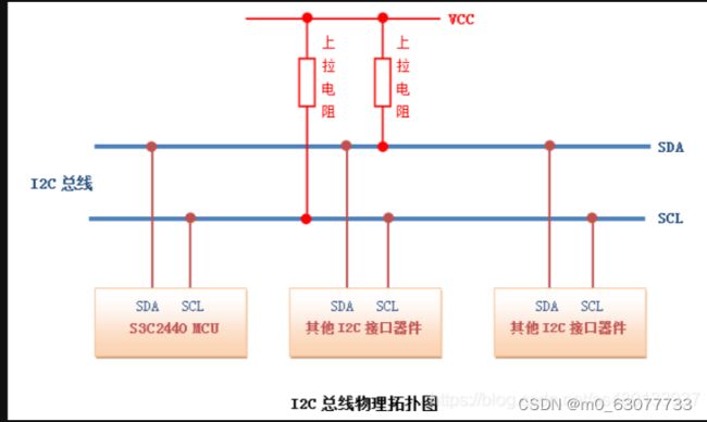
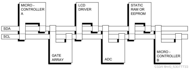
1)IIC:SCL,SDA【只有一条数据线-->半双工】
2)SPI:CS,MOSI,MISO,SCK【有两条数据线-->全双工】
MOSI,MISO,SCK共用
SPI的速率比IIC快
地址/片选
IIC和SPI都可以挂载多个设备
SPI有CS(片选线)可以选择从机【SPI是通过CS选择来区分不同设备的】
IIC是通过传输要进行通信的地址【通过帧格式】
读取数据的位置
IIC是在时钟线的高电平的时候读取【并且在此期间要保持数据的稳定】
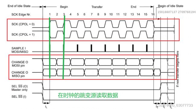
SPI是在时钟线的跳变沿读取数据
IIC:先将时钟拉高,然后SDA从低到高表示要开始发数据,SDA从高到低表示要结束发送数据。
IIC信号在数据传输过程中,当SCL=1高电平时,数据线SDA必须保持稳定状态,不允许有电平跳变,只有在时钟线上的信号为低电平期间,数据线上的高电平或低电平状态才允许变化。
支持挂载设备数量
IIC取决于地址位
SPI取决于CS
SPI通信线的含义
CS:Chip Select片选
SCK:serial clock时钟线
MOSI:Master(主机) Output Salve(从机)In
MISO:Master(主机)In Salve(从机)Output
GND
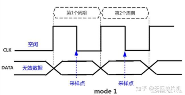
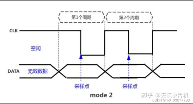
2.SPI配置和时序分析
参考博客:
一文搞懂spi协议4种模式时序 - 知乎
1.上升沿取数据
2.下降沿取数据
3.时钟线空闲时为高电平
4.时钟线空闲时为低电平
3.SPI传输速率
取决于通信设置,采样率能否低于SPI通信速率
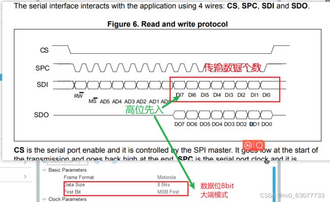
4.LIS3DH时序图分析
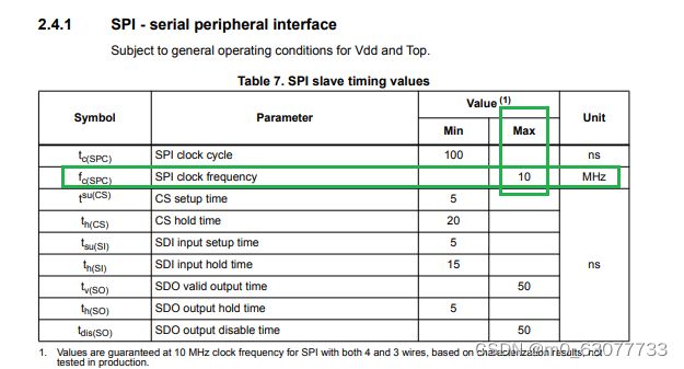
1)速率不高于10MHZ
2)时钟线空闲时为高电平
3)在时钟线的第二个跳变沿取数据(也就是第一个上升沿)
5. 软件设计模式-低耦合 高内聚
低耦合好处:提升可移植性、高可维护性、便于合作、提高问题的解决效率等等
内聚表示一个模块内各个元素彼此结合的紧密程度,标志是不可再拆分
三、LIS3DH驱动移植
1.官方代码的下载
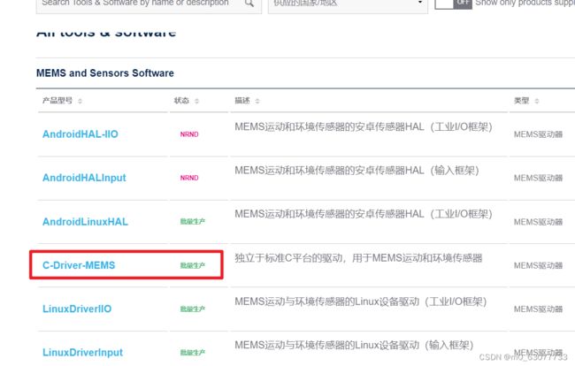
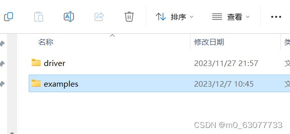
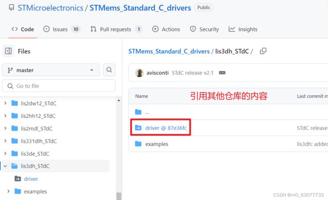
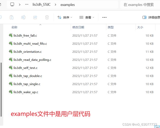
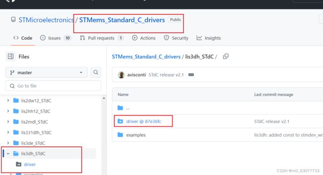
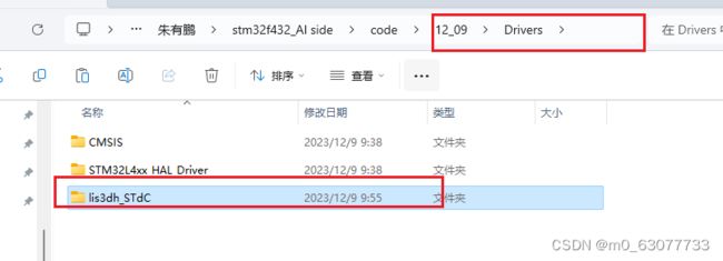
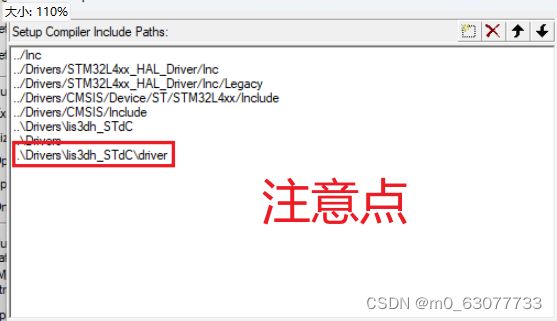
根据相关模块的名字我们可以去百度搜索。由我上面的【LIS3DHTR:加速度传感器】第一部分中可以知道官方的driver文件夹是空的。所以我们根据官方的github去下载
然后将下载的真正的drivers驱动文件复制到drivers中
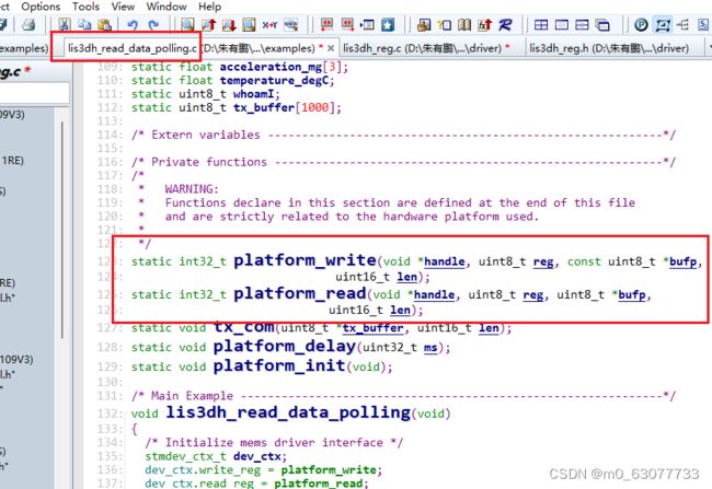
2.ST官方驱动解析(lis3dh_reg.c/h)
![]()
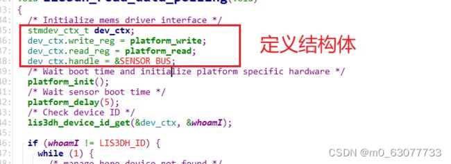
1.stmdev_ctx_t
![]()
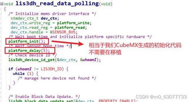
2.lis3dh_read_data_polling
轮询读取数据
初始化后面要延时一下,等待一下。
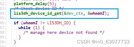
判断一下当前操作的寄存器是否是我们要进行操作的
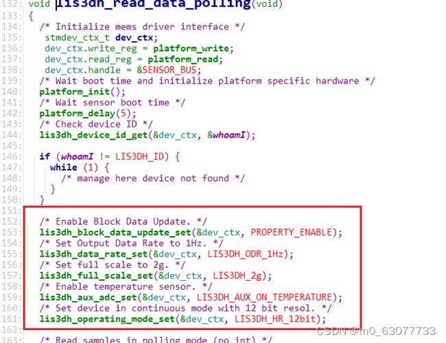
初始化传感器的配置,可以根据自身需求进行初始化
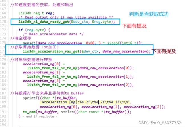
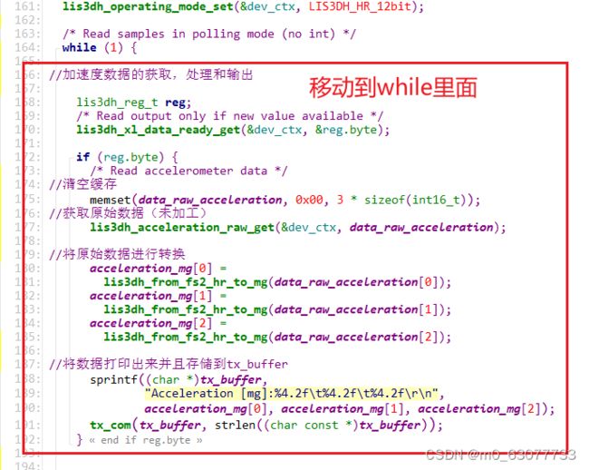
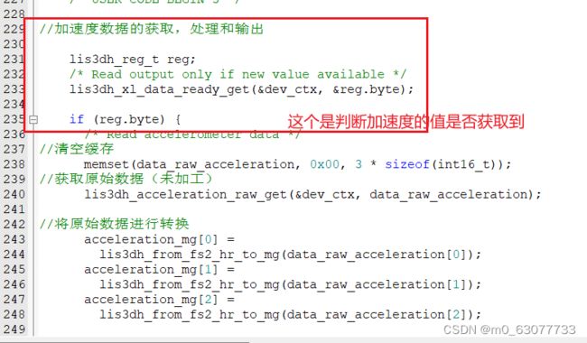
加速度数据的获取,处理和输出
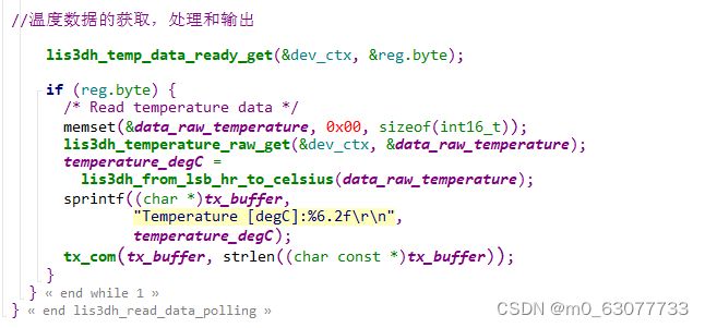
温度数据的获取,处理和输出
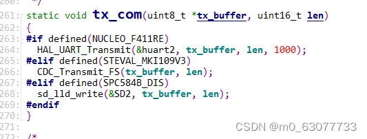
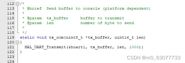
tx_com:串口输出
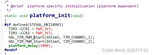
3.platform_init
根据所使用的平台来进行判断
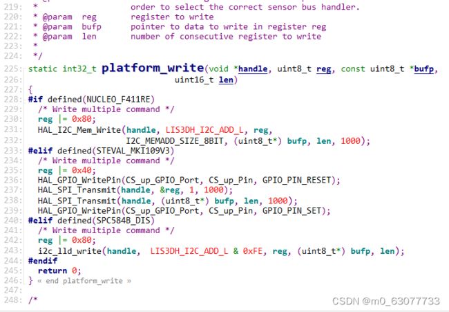
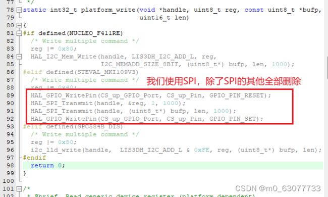
4.platform_write
5.platform_read
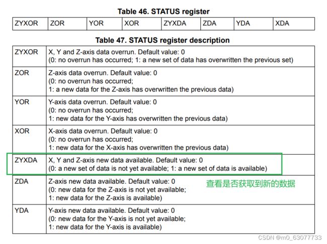
5.lis3dh_xl_data_ready_get:判断速度是否读取成功
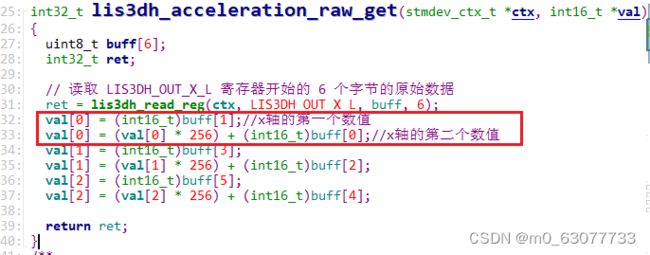
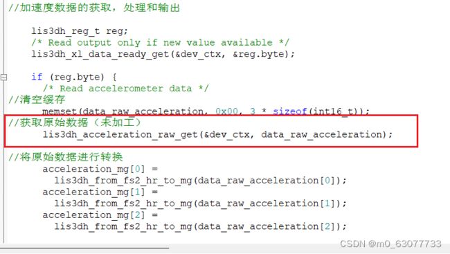
6.lis3dh_acceleration_raw_get:读取速度原始数据
6.lis3dh_temp_data_ready_get:判断温度是否读取成功
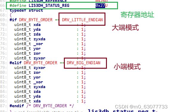
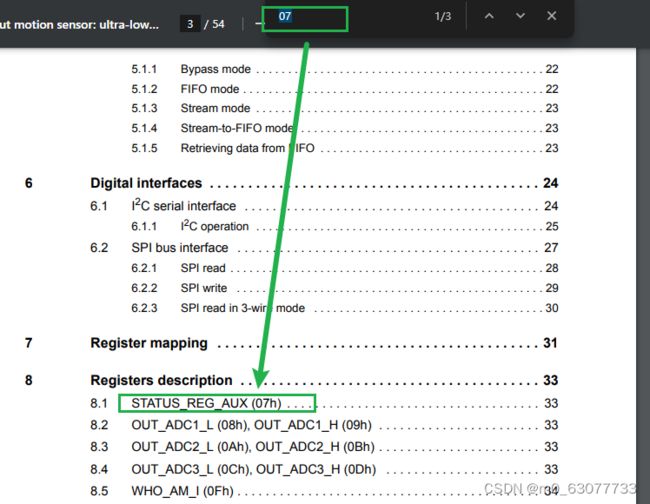
我们通过寄存器的地址可以直接去数据手册中查看
3.使用CubeMX
0.CubeMXL4xx的安装
下载相关CubeMX安装包
下载地址:意法半导体-STMicroelectronics
参考博客:【STM32】STM32的Cube和HAL生态-CSDN博客
将依赖包导入
1.使能调试接口
2.使能外部时钟(准确)
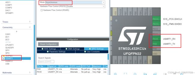
3.串口配置
4.配置SPI
5.配置GPIO用于驱动LED
1.使能调试接口
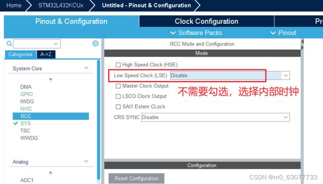
2.使能内部时钟(准确)
判断是否有外部时钟,查看原理图
3.串口配置
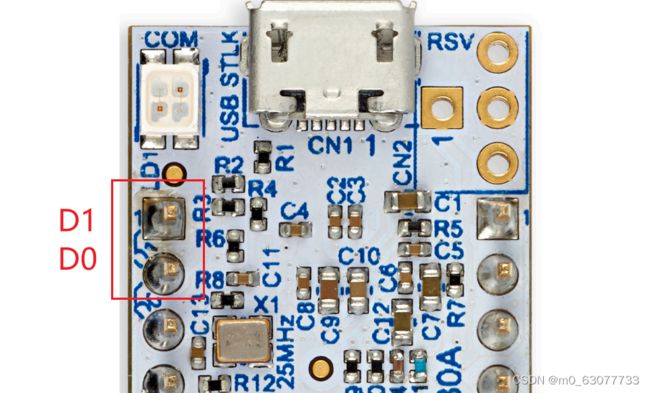
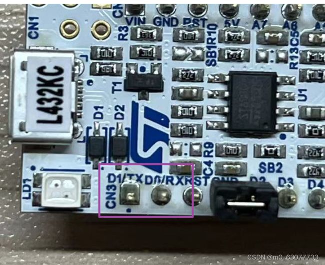
对应开发板上有已经设置好的串口引脚,我们直接使用,比较方便。
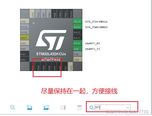
4.配置SPI
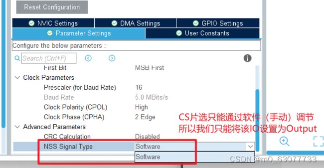
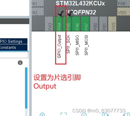
查看这几个引脚是否有接到其他外设上,如果没有则可以使用
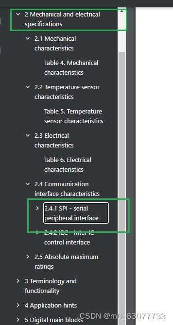
设置SPI参数,我们不知道可以直接去百度或者查看datasheet【SPI章节】
数据位
数据传输速率
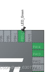
5.配置GPIO用于驱动LED
设置为Output
6.接线
4.代码编写
0.MDK pack安装
下载地址:Arm Keil | Devices
参考博客:【STM32】STM32的Cube和HAL生态-CSDN博客
Arm Keil | Devices
![]()
1.点亮led
  while (1)
  {
		//高电平有效
		// HAL_GPIO_WritePin(LED_Green_GPIO_Port, LED_Green_Pin, GPIO_PIN_SET);
		HAL_GPIO_TogglePin(LED_Green_GPIO_Port, LED_Green_Pin);
		HAL_Delay(500);
    /* USER CODE END WHILE */

    /* USER CODE BEGIN 3 */
  }
2.代码移动
5.代码移植
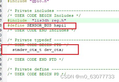
1.结构体等基本移植
2.write移植
3.read移植
与write的思路一样
4.tx_com移植
5.移植后的mian
/* USER CODE BEGIN Header */
/**
  ******************************************************************************
  * @file           : main.c
  * @brief          : Main program body
  ******************************************************************************
  * @attention
  *
  * Copyright (c) 2023 STMicroelectronics.
  * All rights reserved.
  *
  * This software is licensed under terms that can be found in the LICENSE file
  * in the root directory of this software component.
  * If no LICENSE file comes with this software, it is provided AS-IS.
  *
  ******************************************************************************
  */
/* USER CODE END Header */
/* Includes ------------------------------------------------------------------*/
#include "main.h"
#include "spi.h"
#include "usart.h"
#include "gpio.h"

/* Private includes ----------------------------------------------------------*/
/* USER CODE BEGIN Includes */
#include  "lis3dh_reg.h"
#define SENSOR_BUS hspi1
static uint8_t whoamI;
/* USER CODE END Includes */

/* Private typedef -----------------------------------------------------------*/
/* USER CODE BEGIN PTD */
  stmdev_ctx_t dev_ctx;
extern UART_HandleTypeDef huart1;
/* USER CODE END PTD */

/* Private define ------------------------------------------------------------*/
/* USER CODE BEGIN PD */

/* USER CODE END PD */

/* Private macro -------------------------------------------------------------*/
/* USER CODE BEGIN PM */

/* USER CODE END PM */

/* Private variables ---------------------------------------------------------*/

/* USER CODE BEGIN PV */

/* USER CODE END PV */

/* Private function prototypes -----------------------------------------------*/
void SystemClock_Config(void);
/* USER CODE BEGIN PFP */

/* USER CODE END PFP */

/* Private user code ---------------------------------------------------------*/
/* USER CODE BEGIN 0 */

static int32_t platform_write(void *handle, uint8_t reg, const uint8_t *bufp,
                              uint16_t len);
static int32_t platform_read(void *handle, uint8_t reg, uint8_t *bufp,
                             uint16_t len);

static void tx_com(uint8_t *tx_buffer, uint16_t len);
/*
 * @brief  Write generic device register (platform dependent)
 *
 * @param  handle    customizable argument. In this examples is used in
 *                   order to select the correct sensor bus handler.
 * @param  reg       register to write
 * @param  bufp      pointer to data to write in register reg
 * @param  len       number of consecutive register to write
 *
 */
static int32_t platform_write(void *handle, uint8_t reg, const uint8_t *bufp,
                              uint16_t len)
{
  reg |= 0x40;
  HAL_GPIO_WritePin(SPI1_CS_GPIO_Port, SPI1_CS_Pin, GPIO_PIN_RESET);
  HAL_SPI_Transmit(handle, ®, 1, 1000);
  HAL_SPI_Transmit(handle, (uint8_t*) bufp, len, 1000);
  HAL_GPIO_WritePin(SPI1_CS_GPIO_Port, SPI1_CS_Pin, GPIO_PIN_SET);

  return 0;
}

/*
 * @brief  Read generic device register (platform dependent)
 *
 * @param  handle    customizable argument. In this examples is used in
 *                   order to select the correct sensor bus handler.
 * @param  reg       register to read
 * @param  bufp      pointer to buffer that store the data read
 * @param  len       number of consecutive register to read
 *
 */
static int32_t platform_read(void *handle, uint8_t reg, uint8_t *bufp,
                             uint16_t len)
{
  reg |= 0xC0;
  HAL_GPIO_WritePin(SPI1_CS_GPIO_Port, SPI1_CS_Pin, GPIO_PIN_RESET);
  HAL_SPI_Transmit(handle, ®, 1, 1000);
  HAL_SPI_Receive(handle, bufp, len, 1000);
  HAL_GPIO_WritePin(SPI1_CS_GPIO_Port, SPI1_CS_Pin, GPIO_PIN_SET);

  return 0;
}

/*
 * @brief  Send buffer to console (platform dependent)
 *
 * @param  tx_buffer     buffer to transmit
 * @param  len           number of byte to send
 *
 */
static void tx_com(uint8_t *tx_buffer, uint16_t len)
{
  HAL_UART_Transmit(&huart1, tx_buffer, len, 1000);
}


/* USER CODE END 0 */

/**
  * @brief  The application entry point.
  * @retval int
  */
int main(void)
{
  /* USER CODE BEGIN 1 */

  /* USER CODE END 1 */

  /* MCU Configuration--------------------------------------------------------*/

  /* Reset of all peripherals, Initializes the Flash interface and the Systick. */
  HAL_Init();

  /* USER CODE BEGIN Init */

  /* USER CODE END Init */

  /* Configure the system clock */
  SystemClock_Config();

  /* USER CODE BEGIN SysInit */

  /* USER CODE END SysInit */

  /* Initialize all configured peripherals */
  MX_GPIO_Init();
  MX_USART1_UART_Init();
  MX_SPI1_Init();
  /* USER CODE BEGIN 2 */
  dev_ctx.write_reg = platform_write;
  dev_ctx.read_reg = platform_read;
  dev_ctx.handle = &SENSOR_BUS;

	  lis3dh_device_id_get(&dev_ctx, &whoamI);

  if (whoamI != LIS3DH_ID) {
    while (1) {
      /* manage here device not found */
    }
  }
  /* USER CODE END 2 */

  /* Infinite loop */
  /* USER CODE BEGIN WHILE */
  while (1)
  {
		//高电平有效
		// HAL_GPIO_WritePin(LED_Green_GPIO_Port, LED_Green_Pin, GPIO_PIN_SET);
		HAL_GPIO_TogglePin(LED_Green_GPIO_Port, LED_Green_Pin);
		HAL_Delay(500);
    /* USER CODE END WHILE */

    /* USER CODE BEGIN 3 */
  }
  /* USER CODE END 3 */
}

/**
  * @brief System Clock Configuration
  * @retval None
  */
void SystemClock_Config(void)
{
  RCC_OscInitTypeDef RCC_OscInitStruct = {0};
  RCC_ClkInitTypeDef RCC_ClkInitStruct = {0};

  /** Configure the main internal regulator output voltage
  */
  if (HAL_PWREx_ControlVoltageScaling(PWR_REGULATOR_VOLTAGE_SCALE1) != HAL_OK)
  {
    Error_Handler();
  }

  /** Initializes the RCC Oscillators according to the specified parameters
  * in the RCC_OscInitTypeDef structure.
  */
  RCC_OscInitStruct.OscillatorType = RCC_OSCILLATORTYPE_MSI;
  RCC_OscInitStruct.MSIState = RCC_MSI_ON;
  RCC_OscInitStruct.MSICalibrationValue = 0;
  RCC_OscInitStruct.MSIClockRange = RCC_MSIRANGE_6;
  RCC_OscInitStruct.PLL.PLLState = RCC_PLL_ON;
  RCC_OscInitStruct.PLL.PLLSource = RCC_PLLSOURCE_MSI;
  RCC_OscInitStruct.PLL.PLLM = 1;
  RCC_OscInitStruct.PLL.PLLN = 40;
  RCC_OscInitStruct.PLL.PLLP = RCC_PLLP_DIV7;
  RCC_OscInitStruct.PLL.PLLQ = RCC_PLLQ_DIV2;
  RCC_OscInitStruct.PLL.PLLR = RCC_PLLR_DIV2;
  if (HAL_RCC_OscConfig(&RCC_OscInitStruct) != HAL_OK)
  {
    Error_Handler();
  }

  /** Initializes the CPU, AHB and APB buses clocks
  */
  RCC_ClkInitStruct.ClockType = RCC_CLOCKTYPE_HCLK|RCC_CLOCKTYPE_SYSCLK
                              |RCC_CLOCKTYPE_PCLK1|RCC_CLOCKTYPE_PCLK2;
  RCC_ClkInitStruct.SYSCLKSource = RCC_SYSCLKSOURCE_PLLCLK;
  RCC_ClkInitStruct.AHBCLKDivider = RCC_SYSCLK_DIV1;
  RCC_ClkInitStruct.APB1CLKDivider = RCC_HCLK_DIV1;
  RCC_ClkInitStruct.APB2CLKDivider = RCC_HCLK_DIV1;

  if (HAL_RCC_ClockConfig(&RCC_ClkInitStruct, FLASH_LATENCY_4) != HAL_OK)
  {
    Error_Handler();
  }
}

/* USER CODE BEGIN 4 */

/* USER CODE END 4 */

/**
  * @brief  This function is executed in case of error occurrence.
  * @retval None
  */
void Error_Handler(void)
{
  /* USER CODE BEGIN Error_Handler_Debug */
  /* User can add his own implementation to report the HAL error return state */
  __disable_irq();
  while (1)
  {
  }
  /* USER CODE END Error_Handler_Debug */
}

#ifdef  USE_FULL_ASSERT
/**
  * @brief  Reports the name of the source file and the source line number
  *         where the assert_param error has occurred.
  * @param  file: pointer to the source file name
  * @param  line: assert_param error line source number
  * @retval None
  */
void assert_failed(uint8_t *file, uint32_t line)
{
  /* USER CODE BEGIN 6 */
  /* User can add his own implementation to report the file name and line number,
     ex: printf("Wrong parameters value: file %s on line %d\r\n", file, line) */
  /* USER CODE END 6 */
}
#endif /* USE_FULL_ASSERT */
6.polling的移植
将相关缺少的定义补全即可
7.完整移植代码
/* USER CODE BEGIN Header */
/**
  ******************************************************************************
  * @file           : main.c
  * @brief          : Main program body
  ******************************************************************************
  * @attention
  *
  * Copyright (c) 2023 STMicroelectronics.
  * All rights reserved.
  *
  * This software is licensed under terms that can be found in the LICENSE file
  * in the root directory of this software component.
  * If no LICENSE file comes with this software, it is provided AS-IS.
  *
  ******************************************************************************
  */
/* USER CODE END Header */
/* Includes ------------------------------------------------------------------*/
#include "main.h"
#include "spi.h"
#include "usart.h"
#include "gpio.h"

/* Private includes ----------------------------------------------------------*/
/* USER CODE BEGIN Includes */
#include  "lis3dh_reg.h"
#include
#define SENSOR_BUS hspi1
static uint8_t whoamI;
/* USER CODE END Includes */

/* Private typedef -----------------------------------------------------------*/
/* USER CODE BEGIN PTD */
  stmdev_ctx_t dev_ctx;
extern UART_HandleTypeDef huart1;
/* USER CODE END PTD */

/* Private define ------------------------------------------------------------*/
/* USER CODE BEGIN PD */

/* USER CODE END PD */

/* Private macro -------------------------------------------------------------*/
/* USER CODE BEGIN PM */

/* USER CODE END PM */

/* Private variables ---------------------------------------------------------*/

/* USER CODE BEGIN PV */

/* USER CODE END PV */

/* Private function prototypes -----------------------------------------------*/
void SystemClock_Config(void);
/* USER CODE BEGIN PFP */
static int16_t data_raw_acceleration[3];
static int16_t data_raw_temperature;
static float acceleration_mg[3];
static float temperature_degC;
static uint8_t whoamI;
static uint8_t tx_buffer[1000];

/* USER CODE END PFP */

/* Private user code ---------------------------------------------------------*/
/* USER CODE BEGIN 0 */

static int32_t platform_write(void *handle, uint8_t reg, const uint8_t *bufp,
                              uint16_t len);
static int32_t platform_read(void *handle, uint8_t reg, uint8_t *bufp,
                             uint16_t len);

static void tx_com(uint8_t *tx_buffer, uint16_t len);
/*
 * @brief  Write generic device register (platform dependent)
 *
 * @param  handle    customizable argument. In this examples is used in
 *                   order to select the correct sensor bus handler.
 * @param  reg       register to write
 * @param  bufp      pointer to data to write in register reg
 * @param  len       number of consecutive register to write
 *
 */
static int32_t platform_write(void *handle, uint8_t reg, const uint8_t *bufp,
                              uint16_t len)
{
  reg |= 0x40;
  HAL_GPIO_WritePin(SPI1_CS_GPIO_Port, SPI1_CS_Pin, GPIO_PIN_RESET);
  HAL_SPI_Transmit(handle, ®, 1, 1000);
  HAL_SPI_Transmit(handle, (uint8_t*) bufp, len, 1000);
  HAL_GPIO_WritePin(SPI1_CS_GPIO_Port, SPI1_CS_Pin, GPIO_PIN_SET);

  return 0;
}

/*
 * @brief  Read generic device register (platform dependent)
 *
 * @param  handle    customizable argument. In this examples is used in
 *                   order to select the correct sensor bus handler.
 * @param  reg       register to read
 * @param  bufp      pointer to buffer that store the data read
 * @param  len       number of consecutive register to read
 *
 */
static int32_t platform_read(void *handle, uint8_t reg, uint8_t *bufp,
                             uint16_t len)
{
  reg |= 0xC0;
  HAL_GPIO_WritePin(SPI1_CS_GPIO_Port, SPI1_CS_Pin, GPIO_PIN_RESET);
  HAL_SPI_Transmit(handle, ®, 1, 1000);
  HAL_SPI_Receive(handle, bufp, len, 1000);
  HAL_GPIO_WritePin(SPI1_CS_GPIO_Port, SPI1_CS_Pin, GPIO_PIN_SET);

  return 0;
}

/*
 * @brief  Send buffer to console (platform dependent)
 *
 * @param  tx_buffer     buffer to transmit
 * @param  len           number of byte to send
 *
 */
static void tx_com(uint8_t *tx_buffer, uint16_t len)
{
  HAL_UART_Transmit(&huart1, tx_buffer, len, 1000);
}


/* USER CODE END 0 */

/**
  * @brief  The application entry point.
  * @retval int
  */
int main(void)
{
  /* USER CODE BEGIN 1 */

  /* USER CODE END 1 */

  /* MCU Configuration--------------------------------------------------------*/

  /* Reset of all peripherals, Initializes the Flash interface and the Systick. */
  HAL_Init();

  /* USER CODE BEGIN Init */

  /* USER CODE END Init */

  /* Configure the system clock */
  SystemClock_Config();

  /* USER CODE BEGIN SysInit */

  /* USER CODE END SysInit */

  /* Initialize all configured peripherals */
  MX_GPIO_Init();
  MX_USART1_UART_Init();
  MX_SPI1_Init();
  /* USER CODE BEGIN 2 */
  dev_ctx.write_reg = platform_write;
  dev_ctx.read_reg = platform_read;
  dev_ctx.handle = &SENSOR_BUS;

	  lis3dh_device_id_get(&dev_ctx, &whoamI);

  if (whoamI != LIS3DH_ID) {
    while (1) {
      /* manage here device not found */
    }
  }


  /* Enable Block Data Update. */
  lis3dh_block_data_update_set(&dev_ctx, PROPERTY_ENABLE);
  /* Set Output Data Rate to 1Hz. */
  lis3dh_data_rate_set(&dev_ctx, LIS3DH_ODR_1Hz);
  /* Set full scale to 2g. */
  lis3dh_full_scale_set(&dev_ctx, LIS3DH_2g);
  /* Enable temperature sensor. */
  lis3dh_aux_adc_set(&dev_ctx, LIS3DH_AUX_ON_TEMPERATURE);
  /* Set device in continuous mode with 12 bit resol. */
  lis3dh_operating_mode_set(&dev_ctx, LIS3DH_HR_12bit);


  /* USER CODE END 2 */

  /* Infinite loop */
  /* USER CODE BEGIN WHILE */
  while (1)
  {
		//高电平有效
		// HAL_GPIO_WritePin(LED_Green_GPIO_Port, LED_Green_Pin, GPIO_PIN_SET);
		HAL_GPIO_TogglePin(LED_Green_GPIO_Port, LED_Green_Pin);
		HAL_Delay(500);
    /* USER CODE END WHILE */

    /* USER CODE BEGIN 3 */

//加速度数据的获取,处理和输出

    lis3dh_reg_t reg;
    /* Read output only if new value available */
    lis3dh_xl_data_ready_get(&dev_ctx, ®.byte);

    if (reg.byte) {
      /* Read accelerometer data */
//清空缓存
      memset(data_raw_acceleration, 0x00, 3 * sizeof(int16_t));
//获取原始数据(未加工)
      lis3dh_acceleration_raw_get(&dev_ctx, data_raw_acceleration);

//将原始数据进行转换
      acceleration_mg[0] =
        lis3dh_from_fs2_hr_to_mg(data_raw_acceleration[0]);
      acceleration_mg[1] =
        lis3dh_from_fs2_hr_to_mg(data_raw_acceleration[1]);
      acceleration_mg[2] =
        lis3dh_from_fs2_hr_to_mg(data_raw_acceleration[2]);

//将数据打印出来并且存储到tx_buffer
      sprintf((char *)tx_buffer,
              "Acceleration [mg]:%4.2f\t%4.2f\t%4.2f\r\n",
              acceleration_mg[0], acceleration_mg[1], acceleration_mg[2]);
      tx_com(tx_buffer, strlen((char const *)tx_buffer));
    }


//温度数据的获取,处理和输出

    lis3dh_temp_data_ready_get(&dev_ctx, ®.byte);

    if (reg.byte) {
      /* Read temperature data */
      memset(&data_raw_temperature, 0x00, sizeof(int16_t));
      lis3dh_temperature_raw_get(&dev_ctx, &data_raw_temperature);
      temperature_degC =
        lis3dh_from_lsb_hr_to_celsius(data_raw_temperature);
      sprintf((char *)tx_buffer,
              "Temperature [degC]:%6.2f\r\n",
              temperature_degC);
      tx_com(tx_buffer, strlen((char const *)tx_buffer));
    }


  }
  /* USER CODE END 3 */
}

/**
  * @brief System Clock Configuration
  * @retval None
  */
void SystemClock_Config(void)
{
  RCC_OscInitTypeDef RCC_OscInitStruct = {0};
  RCC_ClkInitTypeDef RCC_ClkInitStruct = {0};

  /** Configure the main internal regulator output voltage
  */
  if (HAL_PWREx_ControlVoltageScaling(PWR_REGULATOR_VOLTAGE_SCALE1) != HAL_OK)
  {
    Error_Handler();
  }

  /** Initializes the RCC Oscillators according to the specified parameters
  * in the RCC_OscInitTypeDef structure.
  */
  RCC_OscInitStruct.OscillatorType = RCC_OSCILLATORTYPE_MSI;
  RCC_OscInitStruct.MSIState = RCC_MSI_ON;
  RCC_OscInitStruct.MSICalibrationValue = 0;
  RCC_OscInitStruct.MSIClockRange = RCC_MSIRANGE_6;
  RCC_OscInitStruct.PLL.PLLState = RCC_PLL_ON;
  RCC_OscInitStruct.PLL.PLLSource = RCC_PLLSOURCE_MSI;
  RCC_OscInitStruct.PLL.PLLM = 1;
  RCC_OscInitStruct.PLL.PLLN = 40;
  RCC_OscInitStruct.PLL.PLLP = RCC_PLLP_DIV7;
  RCC_OscInitStruct.PLL.PLLQ = RCC_PLLQ_DIV2;
  RCC_OscInitStruct.PLL.PLLR = RCC_PLLR_DIV2;
  if (HAL_RCC_OscConfig(&RCC_OscInitStruct) != HAL_OK)
  {
    Error_Handler();
  }

  /** Initializes the CPU, AHB and APB buses clocks
  */
  RCC_ClkInitStruct.ClockType = RCC_CLOCKTYPE_HCLK|RCC_CLOCKTYPE_SYSCLK
                              |RCC_CLOCKTYPE_PCLK1|RCC_CLOCKTYPE_PCLK2;
  RCC_ClkInitStruct.SYSCLKSource = RCC_SYSCLKSOURCE_PLLCLK;
  RCC_ClkInitStruct.AHBCLKDivider = RCC_SYSCLK_DIV1;
  RCC_ClkInitStruct.APB1CLKDivider = RCC_HCLK_DIV1;
  RCC_ClkInitStruct.APB2CLKDivider = RCC_HCLK_DIV1;

  if (HAL_RCC_ClockConfig(&RCC_ClkInitStruct, FLASH_LATENCY_4) != HAL_OK)
  {
    Error_Handler();
  }
}

/* USER CODE BEGIN 4 */

/* USER CODE END 4 */

/**
  * @brief  This function is executed in case of error occurrence.
  * @retval None
  */
void Error_Handler(void)
{
  /* USER CODE BEGIN Error_Handler_Debug */
  /* User can add his own implementation to report the HAL error return state */
  __disable_irq();
  while (1)
  {
  }
  /* USER CODE END Error_Handler_Debug */
}

#ifdef  USE_FULL_ASSERT
/**
  * @brief  Reports the name of the source file and the source line number
  *         where the assert_param error has occurred.
  * @param  file: pointer to the source file name
  * @param  line: assert_param error line source number
  * @retval None
  */
void assert_failed(uint8_t *file, uint32_t line)
{
  /* USER CODE BEGIN 6 */
  /* User can add his own implementation to report the file name and line number,
     ex: printf("Wrong parameters value: file %s on line %d\r\n", file, line) */
  /* USER CODE END 6 */
}
#endif /* USE_FULL_ASSERT */
四、NanoEdge AI Studio异常检测工程创建
1.初识
官方说明:
NanoEdgeAIStudio - 面向STM32开发人员的自动化机器学习(ML)工具 - 意法半导体STMicroelectronics
官方参考文档:
AI:NanoEdge AI Studio - stm32mcu (stmicroelectronics.cn)
1)异常检测(AD)库用于检测机器上的异常行为,经过初始的原位训练阶段,使用增量学习模式的动态模型。
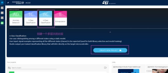
2)n类分类库(nCC)用于区分和识别不同类型的行为,无论异常与否,并使用静态模型将其分类到预先建立的类别中。
3)1类分类(1CC)库用于使用静态模型检测机器上的异常行为,而不提供任何有关预期可能出现的异常的上下文。
4)外推(E)库用于使用静态(回归)模型,使用其他已知参数估计未知目标值。
2.NanoEdge AI Studio工程创建
0.注意点
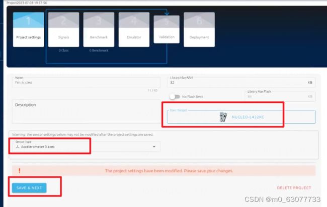
1)名字中不要带空格
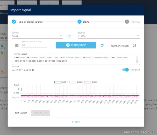
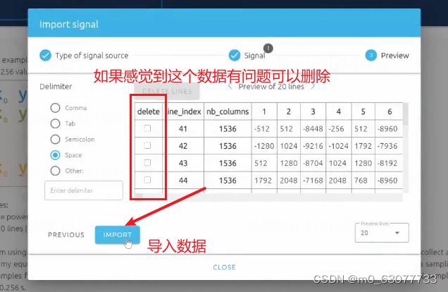
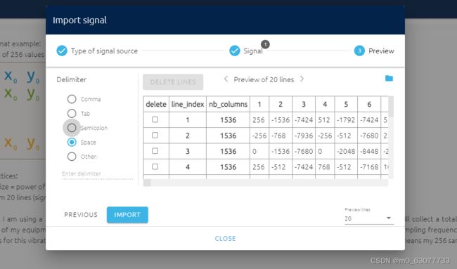
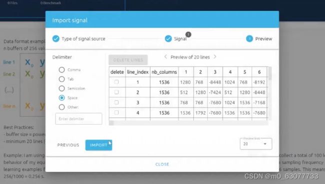
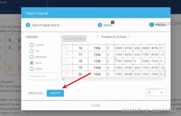
2)数据收集格式--->每一次传输的数据都要是2的n次方【一组数据是3个(x,y,z)】-->如果我们要传输512个数据,则实际上需要传输【3*512=1,536】
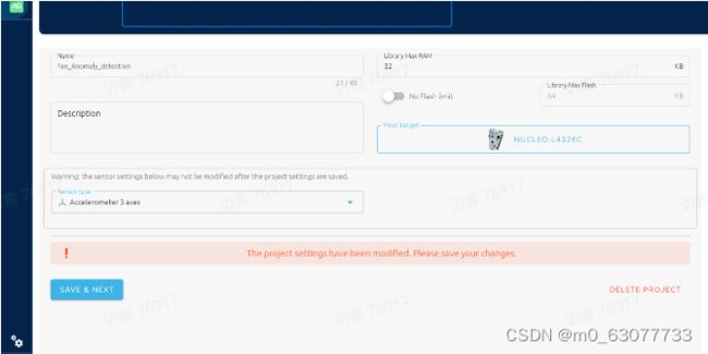
1.硬件选择
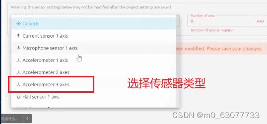
2.传感器选择
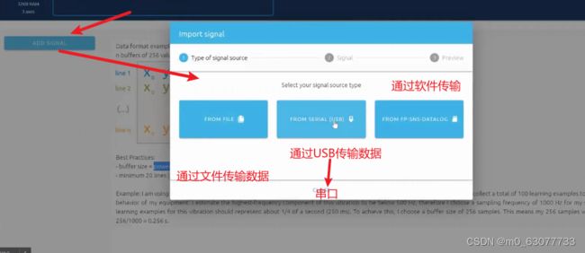
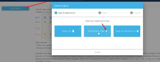
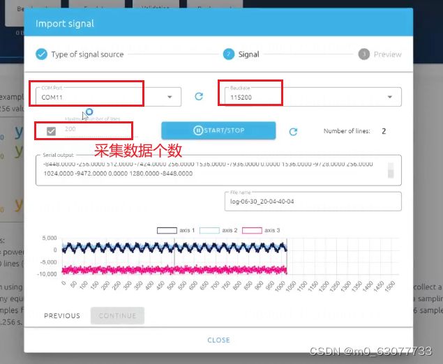
3.数据传输方式选择
4.量程,精度和采样率的设置!!
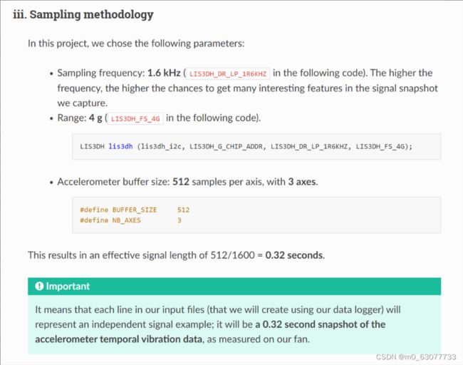
我们需要根据实际需要对传感器的量程,精度,采样率等参数进行修改。可以参考相关文档。
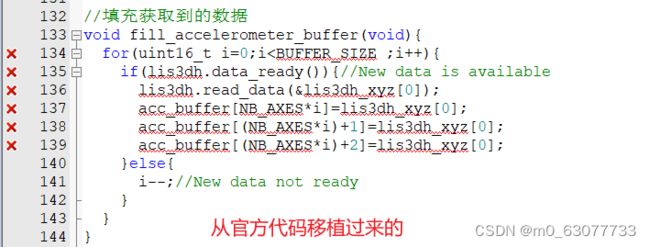
3.二次移植修改官方驱动代码
1.量程设置
1)量程太大,精确度低
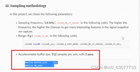
2)根据下图要求,传感器要设置采样频率为1.6KHZ,量程为4g
2.将加速度值获取封装为一个函数
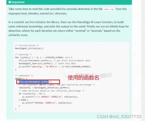
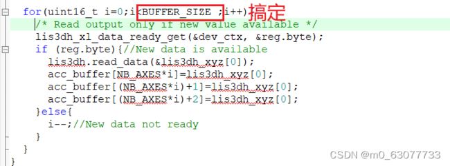
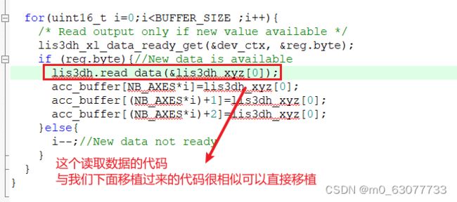
#define BUFFER_SIZE 512*3//一组数据(x,y,z)有3个数值

static int16_t data_raw_acceleration[3];
static int16_t data_raw_temperature;
static float acceleration_mg[3];
static float temperature_degC;
static uint8_t whoamI;
static uint8_t tx_buffer[1000];

//参数大小与【data_raw_acceleration】一样的
static int16_t acc_buffer[BUFFER_SIZE]={0};

void fill_accelerometer_buffer(void){

	  lis3dh_reg_t reg;


	for(uint16_t i=0;i
3.printf重定向
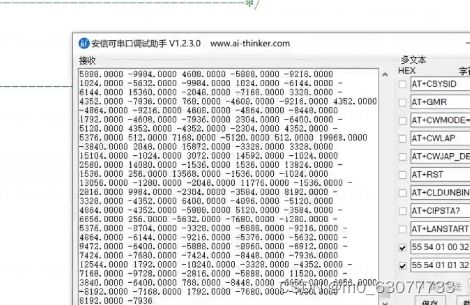
最终获取到的数据存放在【acc_buffer】中,因为要将数据通过串口输出给NanoEdge AI 中,所以我们需要将数据输出。【使用printf】
#ifdef __GNUC__
	#define PUTCHAR_PROTOTYPE int __io_putchar(int ch)
#else
	#define PUTCHAR_PROTOTYPE int fputc(int ch, FILE *f)
#endif
/**
  * @brief  Retargets the C library printf function to the USART.
  * @param  None
  * @retval None
  */
PUTCHAR_PROTOTYPE
{
  /* Place your implementation of fputc here */
  /* e.g. write a character to the EVAL_COM1 and Loop until the end of transmission */
  HAL_UART_Transmit(&huart1, (uint8_t *)&ch, 1, 0xFFFF);
  return ch;
}
设置后记得测试一下串口打印是否正常
4.将数据通过串口的方式推送到NanoEdge AI
由于我们上面设置了【#define BUFFER_SIZE 512*3//一组数据(x,y,z)有3个数值】的时候是512组数据,一组数据3个,所以我们可以直接一一对应上数组,所以我们不需要设置其几轴。
![]()
5.问题查找
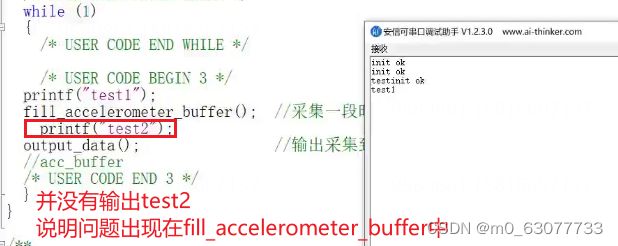
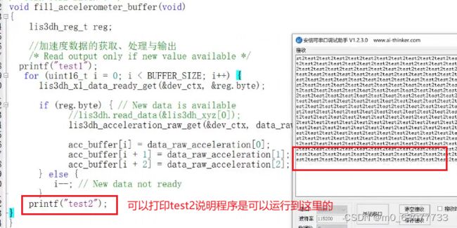
由上面测试可以知道,并没有打印出结果
我们分析可以知道,for循环内部可以打印,for循环外部无法打印
说明可能是for栈溢出,导致进入while(1)循环,无法退出。
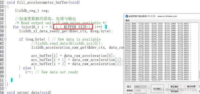
6.一定要按照官方例程去移植代码!!!
重新设置临界条件,就可以输出
但是输出结果还是会卡住!!!!!
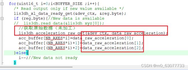
原因:我们没有按照官方示例代码去写,因为我们之前默认我们是使用512*3的数据,所以会出现问题。
#define BUFFER_SIZE 512
#define NB_AXES      3

//参数大小与【data_raw_acceleration】一样的
static float acc_buffer[BUFFER_SIZE]={0};//存放获取到的加速度数据


//填充加速度获取到的数据
void fill_accelerometer_buffer(void){

	  lis3dh_reg_t reg;


	for(uint16_t i=0;i
我们经过上面的修改后,还是无法正常打印出参数。
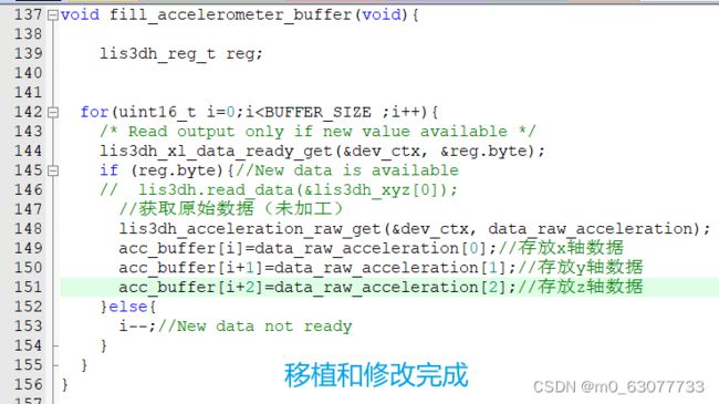
经过检测发现,可能是我们设置的buffer溢出。因为我们要的是BUFFER_SIZE (512)*3
但是我们设置存储数据的acc_buffer容量才为BUFFER_SIZE(512),所以导致溢出。
最后才打印正确
#define BUFFER_SIZE 512
#define NB_AXES      3

//参数大小与【data_raw_acceleration】一样的
static float acc_buffer[BUFFER_SIZE * 3]={0};//存放获取到的加速度数据


//填充加速度获取到的数据
void fill_accelerometer_buffer(void){

	  lis3dh_reg_t reg;


	for(uint16_t i=0;i
7.结合NanoEdge AI使用
注意:此时我们要将传感器严实的粘在风扇上~~~一定要粘严实,不能产生缝隙,如果产生缝隙采集出来的结果会不正确。
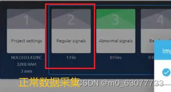
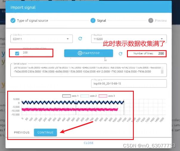
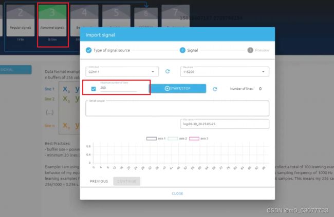
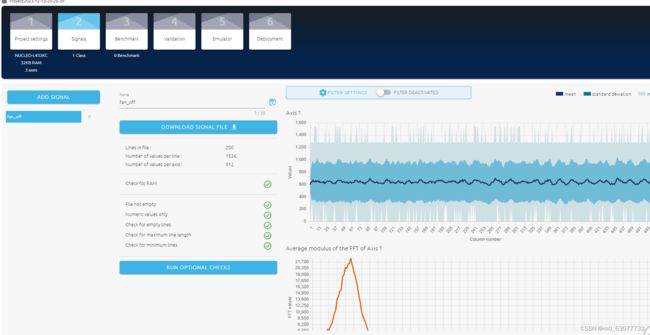
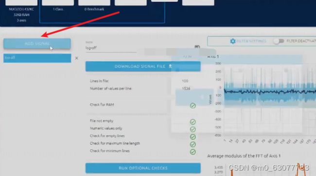
4.数据采集
1.采取正常的数据
2.采集异常的数据
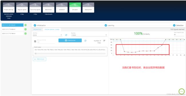
我们在风扇前拿一本书,将气道阻挡住进行测试。
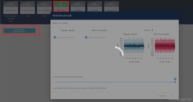
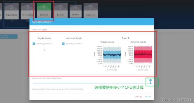
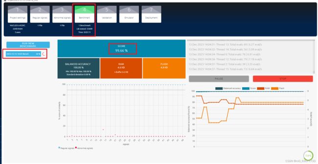
5.算法筛选
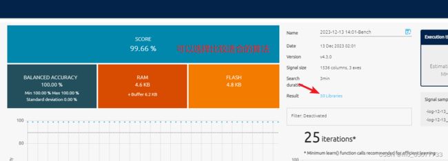
1.将正常和异常算法结合起来
2.使用仿真
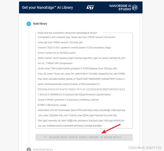
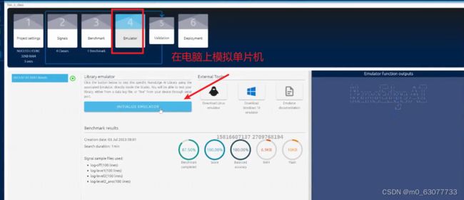
去下载相对应的算法库
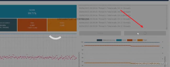
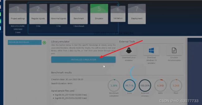
6.算法验证
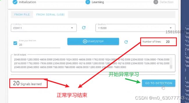
1.正常学习
这个时候让风扇正常转动
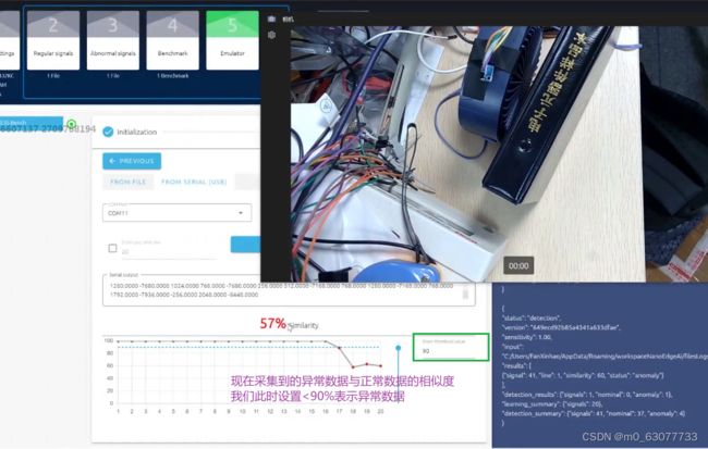
2.异常学习
我们在风扇前拿一本书,将气道阻挡住进行测试。
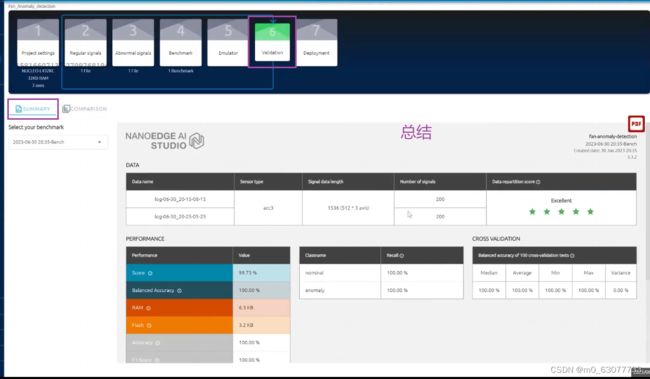
3.最终结果生成
4.为什么每一次启动前都要学习?
因为像风扇,电机类型的期间,随着时间的使用,他会出现老化现象,如果我们就让其学习一次。则会有可能一年后面,本来是使用正常但是由于跟第一次学习相差过大而被判断为异常。所以应该伴随着老化而学习。
7.将生成的文件部署到STM32L432中
1.生成过程
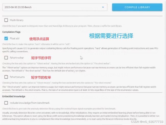
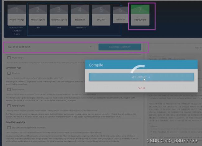
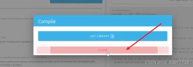
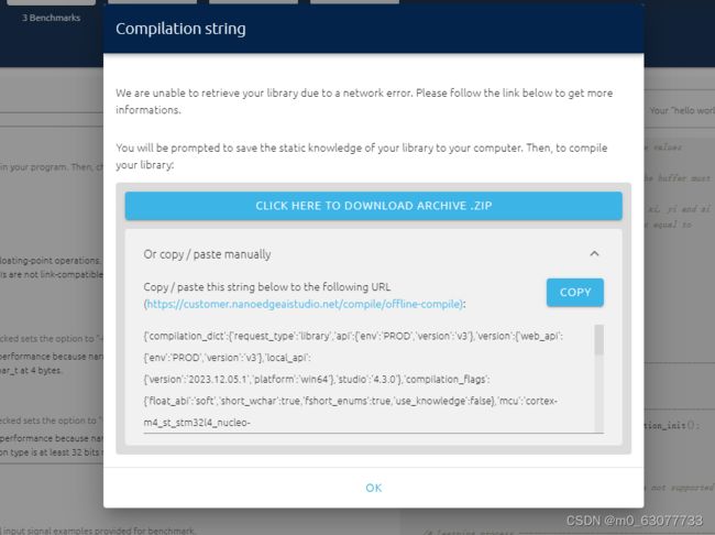
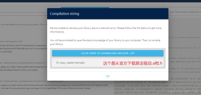
生成.a和.h【包括应该调用.a中的什么函数】文件
这个一定要勾选!!!!!!!【要不然会导入.a文件失败】
2.生成的示例代码
3.查看最终使用的算法AI库
.a:是将c进行编译成的文件,如果不想让甲方知道源码,也可以配合.h文件一起使用
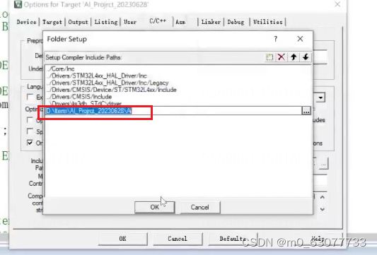
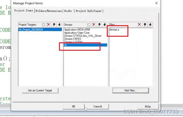
4.将.h和.a文件添加到Keil中跟源程序一起运行
参考博客:
KEIL 编译带.a后缀文件出现的问题_keil调取.a文件-CSDN博客
.a文件打开后一堆乱码
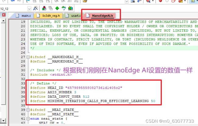
.h文件
5.初始化算法库
由上面的.h文件【neai_anomalydetection_init】
6.调用函数让单片机学习
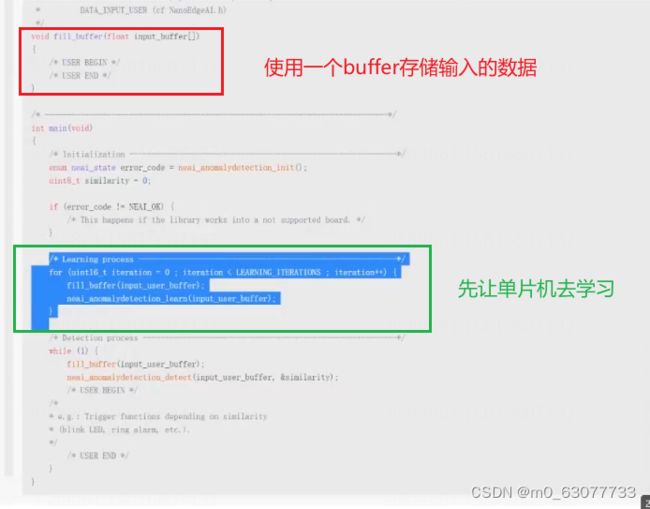
		/* Learning process ----------------------------------------------------------*/
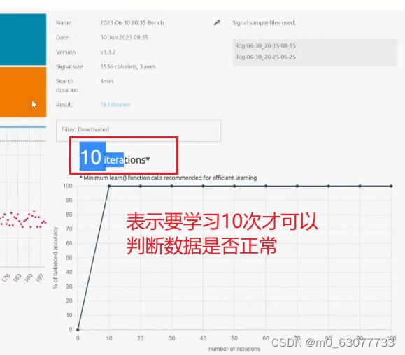
	for (uint16_t iteration = 0 ; iteration < 100 ; iteration++) {
		//fill_buffer(input_user_buffer);
		fill_accelerometer_buffer();
		neai_anomalydetection_learn(acc_buffer);
	}
7.在主函数中调用检测函数
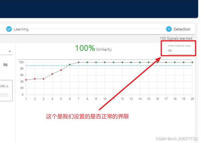
通过这个函数判断:单片机通过学习之后,对于新获取的数据检测是否敏感【相似度】
![]()
//判断准确度
static uint8_t similarity=0;


  while (1)
  {
		fill_accelerometer_buffer();
		//output_data();
		//检测数据是否正常
		neai_anomalydetection_detect(acc_buffer,&similarity);
		printf("similarity=\%%d\r\n");

  }
8.注意点:
我们在编写完上面代码后出现了问题,检查发现了
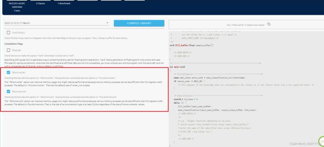
1)我们在生成.a和.h文件时,要勾选下面两个选项!!!!!!!!!
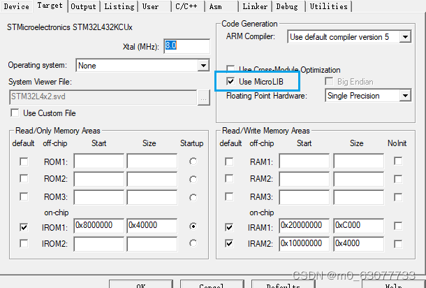
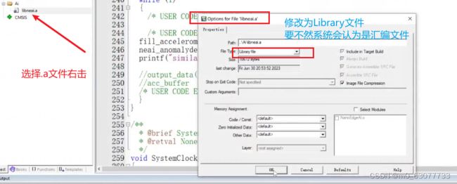
2)导入.a文件后,一定要将其文件类型选择为“Library File"!!!!!!!!!!
移植 IAR 静态库(.a)到 keil(MDK)_keil5 移植.a库-CSDN博客
8.识别率低的解决方法
增加Flash、RAM
修改频率、精度
修改缓冲区:缓冲区的长度表示此次采集持续的时间
增加更多的传感器
检查信号质量:是否引入了寄生信号、噪音等
9.优化代码
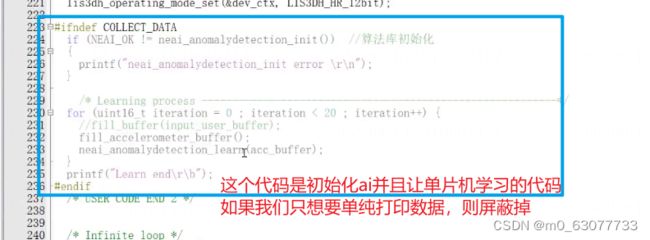
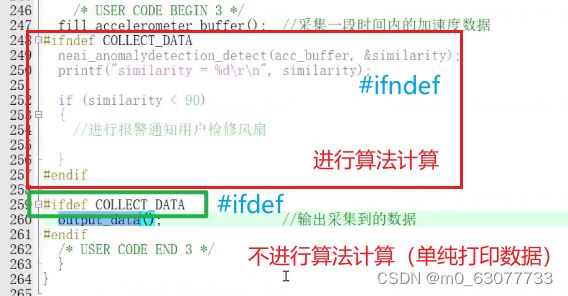
基于之前的工程,添加宏定义。
一方面可以加载模型,一方面可以收集数据
如果想要单独跑算法,则直接将COLLECT_DATA注释起来即可。如果单纯想要打印数据,则不需要注释。
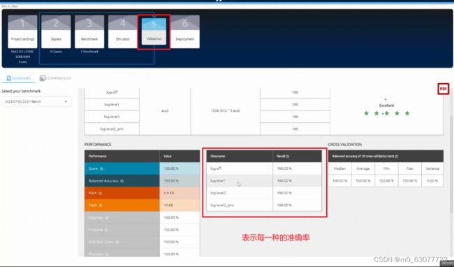
10.NanoEdge AI Studio创建分类检测工程
官方参考文件
AI:How to create a current sensing classifier using NanoEdge AI Studio - stm32mcu
1)一个工程是异常检测【前面的】
2)一个工程是分类(根据手动调节几档风速,使得LIS3DH也可以判断出来)
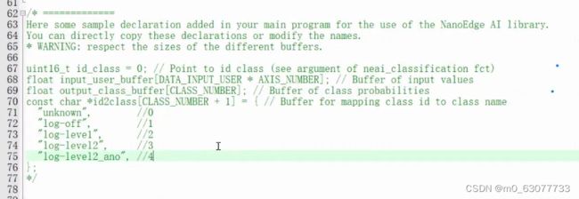
1.数据采集
1)关闭off
2)一档level1
3)二挡level2
4)二挡异常level2_ano
重复上面的操作
2.算法筛选和训练
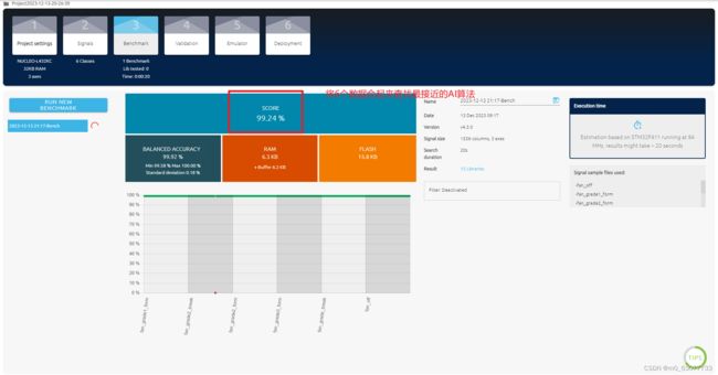
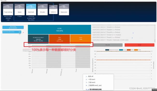
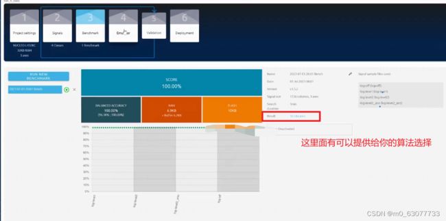
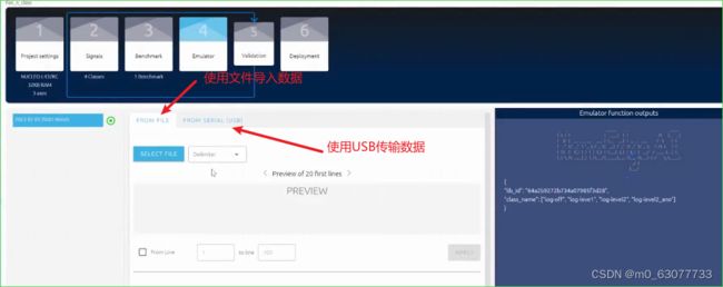
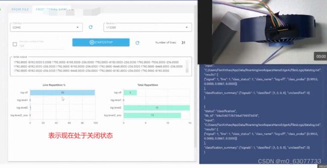
这个时候我们就可以开始模拟
3.下载库和部署
算法的总结
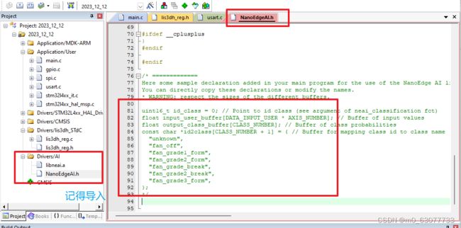
将原来的文件复制一份出来,然后将其修改为class【我们要将其修改为按分类】
我们将下载好的文件解压,然后将其.a和.h进行替换我们原来的文件
4.代码编写
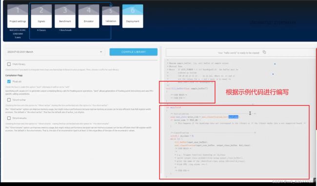
0.官方NanoEdge AI给的参考代码
/* =============
Copyright (c) 2022, STMicroelectronics

All rights reserved.

Redistribution and use in source and binary forms, with or without modification, are permitted provided that
the following conditions are met:

* Redistributions of source code must retain the above copyright notice, this list of conditions and the
  following disclaimer.

* Redistributions in binary form must reproduce the above copyright notice, this list of conditions and the
  following disclaimer in the documentation and/or other materials provided with the distribution.

* Neither the name of the copyright holders nor the names of its contributors may be used to endorse or promote
  products derived from this software without specific prior written permission.

*THIS SOFTWARE IS PROVIDED BY THE COPYRIGHT HOLDERS AND CONTRIBUTORS "AS IS" AND ANY EXPRESS OR IMPLIED WARRANTIES,
INCLUDING, BUT NOT LIMITED TO, THE IMPLIED WARRANTIES OF MERCHANTABILITY AND FITNESS FOR A PARTICULAR PURPOSE ARE
DISCLAIMED. IN NO EVENT SHALL THE COPYRIGHT HOLDER / OWNER OR CONTRIBUTORS BE LIABLE FOR ANY DIRECT, INDIRECT, INCIDENTAL,
SPECIAL, EXEMPLARY, OR CONSEQUENTIAL DAMAGES (INCLUDING, BUT NOT LIMITED TO, PROCUREMENT OF SUBSTITUTE GOODS OR
SERVICES; LOSS OF USE, DATA, OR PROFITS; OR BUSINESS INTERRUPTION) HOWEVER CAUSED AND ON ANY THEORY OF LIABILITY,
WHETHER IN CONTRACT, STRICT LIABILITY, OR TORT (INCLUDING NEGLIGENCE OR OTHERWISE) ARISING IN ANY WAY OUT OF THE
USE OF THIS SOFTWARE, EVEN IF ADVISED OF THE POSSIBILITY OF SUCH DAMAGE.*
*/
/**
  **************************************************************************
  * Demo: NanoEdge AI process to include in main program body
  *
  * @note  This program must be completed and customized by the user
  **************************************************************************
  */

/* Includes --------------------------------------------------------------------*/
#include "NanoEdgeAI.h"
#include "knowledge.h"
/* Private define --------------------------------------------------------------*/
/* Private variables defined by user -------------------------------------------*/
float input_user_buffer[DATA_INPUT_USER * AXIS_NUMBER]; // Buffer of input values
float output_class_buffer[CLASS_NUMBER]; // Buffer of class probabilities
/* Private function prototypes defined by user ---------------------------------*/
/*
 * @brief Collect data process
 *
 * This function is defined by user, depends on applications and sensors
 *
 * @param sample_buffer: [in, out] buffer of sample values
 * @retval None
 * @note   If AXIS_NUMBER = 3 (cf NanoEdgeAI.h), the buffer must be
 *         ordered as follow:
 *         [x0 y0 z0 x1 y1 z1 ... xn yn zn], where xi, yi and zi
 *         are the values for x, y and z axes, n is equal to
 *         DATA_INPUT_USER (cf NanoEdgeAI.h)
 */
void fill_buffer(float sample_buffer[])
{
	/* USER BEGIN */
	/* USER END */
}
/* -----------------------------------------------------------------------------*/
int main(void)
{
	/* Initialization ------------------------------------------------------------*/
	enum neai_state error_code = neai_classification_init(knowledge);
	if (error_code != NEAI_OK) {
		/* This happens if the knowledge does not correspond to the library or if the library works into a not supported board. */
	}

	/* Classification ------------------------------------------------------------*/
	uint16_t id_class = 0;
	while (1) {
		fill_buffer(input_user_buffer);
		neai_classification(input_user_buffer, output_class_buffer, &id_class);
		/* USER BEGIN */
		/*
		* e.g.: Trigger functions depending on id_class
		* (print output class probabilities using output_class_buffer[],
		* print the name of the identified class using id2class[id_class],
		* blink LED, ring alarm, etc.).
		*/
		/* USER END */
	}
}
1.导入头文件
2.初始化
3.将获取到的数据输出
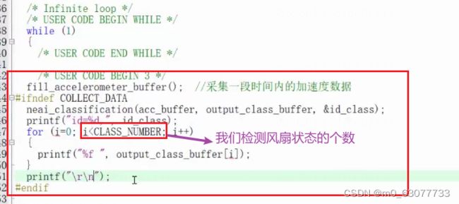
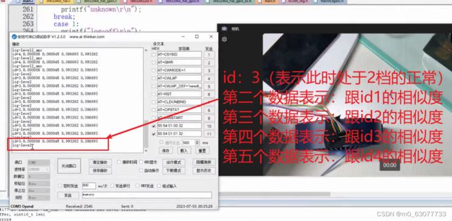
![]()
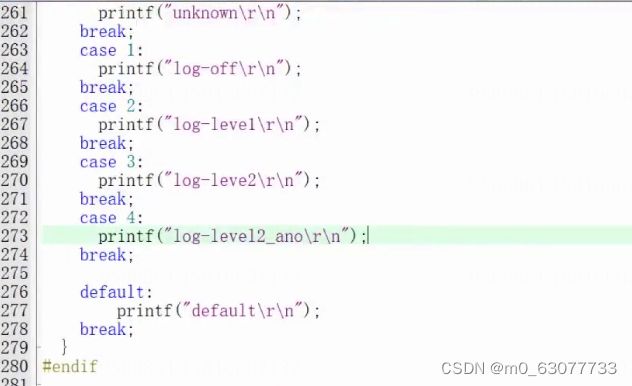
4.id分类
5.测试结果
5.如何获取knowledge.h文件
我们在最后生成代码中
【第一次从官方下载的.zip中是只包含:NanoEdgeAI.h和libneai.a】
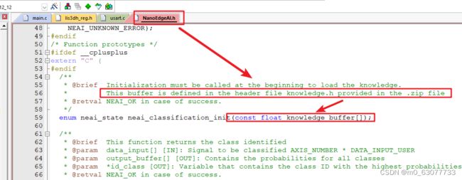
但是我们在“NanoEdgeAI.h”中使用到的AI初始化函数中需要调用另外一个头文件“#include "42_knowledge.h"”中定义的变量【 knowledge[992]】
【那么我们从哪里获取这个“knowledge.h”文件呢???】--->【其实我们在NanoEdge AI Studio 最后从官方下载AI驱动代码的位置,在一次选择下载,则第二次下载的就是对应AI的knowledge.h文件】
在这一次代码中我们的【#include "NanoEdgeAI.h"】
11.额外模块:蜂鸣器
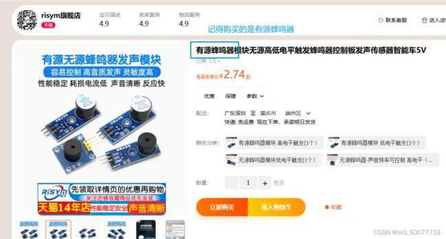
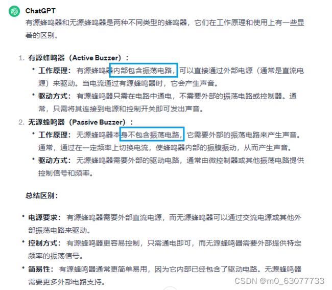
1.有源蜂鸣器VS无源蜂鸣器
2.基本控制
当风扇的风道被挡住的时候,让蜂鸣器响。【当风速为1档的时候,持续响1s,当风速为2档的时候,持续响3s】
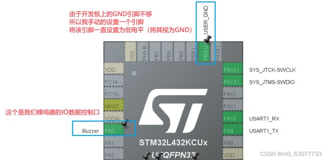
因为是我们人为的控制蜂鸣器响与否,所以应该将这个Buzzer设置为输出模式【如果你要读从引脚取数据,则设置为输入模式】
  while (1)
  {
		//由于我们的GND引脚不足,所以我们手动的将一个GPIO设置为低电平
		 /*Configure GPIO pin Output Level */
		HAL_GPIO_WritePin(GPIOB, Buzzzer_Pin|USER_GND_Pin, GPIO_PIN_RESET);

		fill_accelerometer_buffer();
		//output_data();

		// This function returns the class identified
		neai_classification(acc_buffer, output_class_buffer, &id_class);
		//CLASS_NUMBER:对应的模式个数
			for (uint8_t i=0; i
12.额外模块:OLED
https://www.cnblogs.com/xuyan123/p/14134246.html


