USB -- STM32F103 USB DFU设备固件升级(IAP)控制传输讲解(六)
目录
链接快速定位
前沿
1 描述符讲解
1.1 设备描述符
1.2 配置描述符
1.3 接口描述符
1.4 功能描述符
1.5 端点描述符
1.6 字符串描述符
2 基本命令简介
2.1 DFU基本命令
2.2 命令解析
3 关键函数讲解
3.1 接口函数讲解
3.1.1 初始化函数讲解
3.1.2 擦除函数讲解
3.1.3 读函数讲解
3.1.4 写函数讲解
3.1.5 获取状态函数讲解
3.2 GPIO配置讲解
3.3 中断函数讲解--USB复位函数讲解
3.4 主函数讲解
4 代码演示
4.1 修改按键IO口
4.2 准备APP工程文件
4.3 下载DFU上位机软件
4.4 运行演示
链接快速定位
USB -- 初识USB协议(一)
源码下载请参考链接:USB -- STM32-FS-USB-Device驱动代码简述(二)
USB -- STM32F103虚拟串口bulk传输讲解(三)
USB -- STM32F103自定义HID设备及HID上位机中断传输讲解(四)
USB -- STM32F103 U盘(MassStorage)SDIO接口SCSI协议Bulk传输讲解(五)
DFU数据手册
DFU工具下载
前沿
前面两节主要是对USB的基本概念做了简单讲解,学习USB的最本质目的还是要回到USB的应用方向,接下来的几章主要讲解USB的各类应用,包括:
- 虚拟串口(环回测试)-- bulk传输(USB -- STM32F103虚拟串口bulk传输讲解(三))
- 自定义HID -- 中断传输(USB -- STM32F103自定义HID设备及HID上位机中断传输讲解(四))
- U盘 -- bulk传输(USB -- STM32F103 U盘(MassStorage)SDIO接口SCSI协议Bulk传输讲解(五))
- 在线固件升级(DFU)-- 控制传输(本章讲解)
- 语音录制及播放 -- 同步传输
- 照相机 -- 同步传输
- 复合设备 -- 中断+bulk传输
主要还是带领大家找相关的资料及相关的工具和代码。
1 描述符讲解
描述符是USB能够正常通信的前提,没有描述符,USB就不知道当前是什么样的设备,所以描述符在USB整个通信过程中占有十分重要的地位,所以这里重点讲解一下USB的各类描述符。
ST的例程为我们配置好了应用的描述符,我们不需要关注也能正常运行程序,但是我们这里讲解一下怎么通过查找资料来知道具体描述符的含义。
1.1 设备描述符
以下是STM32F103系列的DFU的设备描述符代码(每个字节对应的含义可以在USB -- 初识USB协议(一)中查看):
uint8_t DFU_DeviceDescriptor[DFU_SIZ_DEVICE_DESC] =
  {
    0x12,   /* bLength */
    0x01,   /* bDescriptorType */
    0x00,   /* bcdUSB, version 1.00 */
    0x01,
    0x00,   /* bDeviceClass : See interface */
    0x00,   /* bDeviceSubClass : See interface*/
    0x00,   /* bDeviceProtocol : See interface */
    bMaxPacketSize0, /* bMaxPacketSize0 0x40 = 64 */
    0x83,   /* idVendor     (0483) */
    0x04,
    0x11,   /* idProduct (0xDF11) DFU PiD*/
    0xDF,
    0x00,   /* bcdDevice*/
    0x02,

    0x01,   /* iManufacturer : index of string Manufacturer  */
    0x02,   /* iProduct      : index of string descriptor of product*/
    0x03,   /* iSerialNumber : index of string serial number*/

    0x01    /*bNumConfigurations */
  };
设备描述符顾名思义就是描述USB设备的基本信息,主要包括以下信息:
- USB版本号
- USB设备类型
- USB设备协议
- 端点0最大传输大小(最大64byte)
- 厂商向USBIF申请的VID(需付费,由芯片厂商提供)
- 设备PID(厂商自定义)
- 制造商的字符串描述符索引(描述生产这个产品的厂商)
- 产品的字符串描述符索引(描述是什么产品)
- 设备序号的字符串描述符索引(主要是芯片的UID)
- 配置的数量(一般为1)
设备类型可以通过USB官网Class查询,我们这里是DFU设备,所以bDeviceClass=0xEF,bDeviceSubClass=0x01,bDeviceProtocol=0x01。
但实际这里的bDeviceClass=0x00,是因为0x00表示class可以在接口与描述符中定义。
制造商的字符串描述符索引、产品的字符串描述符索引和设备序号的字符串描述符索引主要是制造商、产品和设备序列号在字符串描述符的索引位置。
比如这里举个例子,以下三个是字符串描述符,分别是制造商描述符、产品描述符和序列号描述符:
uint8_t DFU_StringVendor[DFU_SIZ_STRING_VENDOR] =
  {
    DFU_SIZ_STRING_VENDOR,
    0x03,
    /* Manufacturer: "STMicroelectronics" */
    'S', 0, 'T', 0, 'M', 0, 'i', 0, 'c', 0, 'r', 0, 'o', 0, 'e', 0,
    'l', 0, 'e', 0, 'c', 0, 't', 0, 'r', 0, 'o', 0, 'n', 0, 'i', 0,
    'c', 0, 's', 0
  };

uint8_t DFU_StringProduct[DFU_SIZ_STRING_PRODUCT] =
  {
    DFU_SIZ_STRING_PRODUCT,
    0x03,
    /* Product name: "STM32 DFU" */
    'S', 0, 'T', 0, 'M', 0, '3', 0, '2', 0, ' ', 0, 'D', 0, 'F', 0, 'U', 0
  };

uint8_t DFU_StringSerial[DFU_SIZ_STRING_SERIAL] =
  {
    DFU_SIZ_STRING_SERIAL,
    0x03,
    /* Serial number */
    'S', 0, 'T', 0, 'M', 0, '3', 0, '2', 0
  };
由下面代码可知,他们的位置也是根据索引号排列的,所以主机请求index为1的描述符,那么设备就发送制造商描述符给主机,告诉主机USB的制造商是什么。
#ifdef USE_STM3210E_EVAL
 ONE_DESCRIPTOR DFU_String_Descriptor[7] =
#elif defined(USE_STM3210B_EVAL)
 ONE_DESCRIPTOR DFU_String_Descriptor[6] =
#elif defined(USE_STM32L152_EVAL) || defined(USE_STM32L152D_EVAL) ||defined(USE_STM32373C_EVAL) ||defined(USE_STM32303C_EVAL) ||defined(USE_NUCLEO)
 ONE_DESCRIPTOR DFU_String_Descriptor[5] =
#endif /* USE_STM3210E_EVAL */
  {
    {       (uint8_t*)DFU_StringLangId,          DFU_SIZ_STRING_LANGID       },
    {       (uint8_t*)DFU_StringVendor,          DFU_SIZ_STRING_VENDOR       },
    {       (uint8_t*)DFU_StringProduct,         DFU_SIZ_STRING_PRODUCT      },
    {       (uint8_t*)DFU_StringSerial,          DFU_SIZ_STRING_SERIAL       },
    {       (uint8_t*)DFU_StringInterface0,      DFU_SIZ_STRING_INTERFACE0   }
#ifdef USE_STM3210B_EVAL
    ,
    {       (uint8_t*)DFU_StringInterface1,      DFU_SIZ_STRING_INTERFACE1   }
#endif /* USE_STM3210B_EVAL */
#ifdef USE_STM3210E_EVAL
    ,
    {       (uint8_t*)DFU_StringInterface1,      DFU_SIZ_STRING_INTERFACE1   },
    {       (uint8_t*)DFU_StringInterface2_1,    DFU_SIZ_STRING_INTERFACE2   }
#endif /* USE_STM3210E_EVAL */
  };
如果设备描述符的索引值修改了,那么String_Descriptor数组存放数据的顺序也需要相应的修改。
VID可以通过USB官网:USB_Members查看,比如这里的是ST的VID,0x0483的10进制是1155,我们在USB官网查看,如下:
![]()
1.2 配置描述符
配置描述符顾名思义就是描述USB设备的配置信息,主要包括以下信息:
- USB接口的数量(会在接口描述符讲解)
- USB的配置值(一般为1,根据设备描述符配置数量决定)
- USB的供电信息
- USB的最大电流
const uint8_t DFU_ConfigDescriptor[] =
  {
    0x09,   /* bLength: Configuration Descriptor size */
    0x02,   /* bDescriptorType: Configuration */
    DFU_SIZ_CONFIG_DESC, /* wTotalLength: Bytes returned */
    0x00,
    0x01,   /* bNumInterfaces: 1 interface */
    0x01,   /* bConfigurationValue: */
    /*      Configuration value */
    0x00,   /* iConfiguration: */
    /*      Index of string descriptor */
    /*      describing the configuration */
    0x80,   /* bmAttributes: */
    /*      bus powered */
    0x20,   /* MaxPower 100 mA: this current is used for detecting Vbus */
  }
1.3 接口描述符
这里的接口描述符有1个,由配置描述符指定个数,但是这里存在3个备用设置选项,主要是描述三种不同的FLASH存储,通过iInterface指定字符串描述符,这里从0x04开始是因为0x00 0x01 0x02被设备描述符所占用了(当然我们本节只讲一种FLASH,内部flash,所以其他两个可以忽略),我们举例说明一下含义。
uint8_t DFU_InterfaceDescriptor[ ] =
{
    /************ Descriptor of DFU interface 0 Alternate setting 0 *********/
    0x09,   /* bLength: Interface Descriptor size */
    0x04,   /* bDescriptorType: */
    /*      Interface descriptor type */
    0x00,   /* bInterfaceNumber: Number of Interface */
    0x00,   /* bAlternateSetting: Alternate setting */
    0x00,   /* bNumEndpoints*/
    0xFE,   /* bInterfaceClass: Application Specific Class Code */
    0x01,   /* bInterfaceSubClass : Device Firmware Upgrade Code */
    0x02,   /* nInterfaceProtocol: DFU mode protocol */
    0x04,   /* iInterface: */
    /* Index of string descriptor */
    /* 18 */

    /************ Descriptor of DFU interface 0 Alternate setting 1  **********/

    0x09,   /* bLength: Interface Descriptor size */
    0x04,   /* bDescriptorType: */
    /*      Interface descriptor type */
    0x00,   /* bInterfaceNumber: Number of Interface */
    0x01,   /* bAlternateSetting: Alternate setting */
    0x00,   /* bNumEndpoints*/
    0xFE,   /* bInterfaceClass: Application Specific Class Code */
    0x01,   /* bInterfaceSubClass : Device Firmware Upgrade Code */
    0x02,   /* nInterfaceProtocol: DFU mode protocol */
    0x05,   /* iInterface: */
    /* Index of string descriptor */
    /* 27 */

    /************ Descriptor of DFU interface 0 Alternate setting 2  **********/

    0x09,   /* bLength: Interface Descriptor size */
    0x04,   /* bDescriptorType: */
    /*      Interface descriptor type */
    0x00,   /* bInterfaceNumber: Number of Interface */
    0x02,   /* bAlternateSetting: Alternate setting */
    0x00,   /* bNumEndpoints*/
    0xFE,   /* bInterfaceClass: Application Specific Class Code */
    0x01,   /* bInterfaceSubClass : Device Firmware Upgrade Code */
    0x02,   /* nInterfaceProtocol: DFU mode protocol */
    0x06,   /* iInterface: */
    /* Index of string descriptor */
}首先下载DFU数据手册,打开《DFU_1.1.pdf》文件,找到4.2.3小节,这里有对接口描述符的全部解释。
1.4 功能描述符
uint8_t DFU_FunctionalDescriptor[ ] =
{
    /******************** DFU Functional Descriptor********************/
    0x09,   /*blength = 9 Bytes*/
    0x21,   /* DFU Functional Descriptor*/
    0x0B,   /*bmAttribute

    bitCanDnload             = 1      (bit 0)
    bitCanUpload             = 1      (bit 1)
    bitManifestationTolerant = 0      (bit 2)
    bitWillDetach            = 1      (bit 3)
    Reserved                          (bit4-6)
    bitAcceleratedST         = 0      (bit 7)*/
    0xFF,   /*DetachTimeOut= 255 ms*/
    0x00,
    wTransferSizeB0,
    wTransferSizeB1,          /* TransferSize = 1024 Byte*/
    0x1A,                     /* bcdDFUVersion*/
    0x01
 }
功能描述符也是通过《DFU_1.1.pdf》手册查看具体的功能,这里不展开讲解,需要了解的小伙伴自行查找。
1.5 端点描述符
DFU没有端点描述符,因为它使用的是端点0,端点0在设备描述符中已经有定义。
1.6 字符串描述符
在设备描述符中已经对制造商描述符、产品描述符和设备序号描述符做了说明,这里仅对语言ID描述符做简单说明。
语言ID描述符相对很简单,就是告诉主机用的哪种语言编码,这里一般选择0x0409,使用美国的编码。一般使用最多的也是美国编码。
uint8_t DFU_StringLangId[DFU_SIZ_STRING_LANGID] =
  {
    DFU_SIZ_STRING_LANGID,
    0x03,
    0x09,
    0x04    /* LangID = 0x0409: U.S. English */
};![]()
2 基本命令简介
2.1 DFU基本命令
DFU协议主要由以下7条指令构成:
- DFU_DETACH Request
- DFU_DNLOAD Request
- DFU_GETSTATUS Request
- DFU_CLRSTATUS Request
- DFU_ABORT Request
- DFU_GETSTATE Request
- DFU_UPLOAD Request
在《DFU_1.1.pdf》手册上也能找到相应命令的使用,见下图。具体的命令使用可通过手册查找。
DFU协议的大致流程图如下:
2.2 命令解析
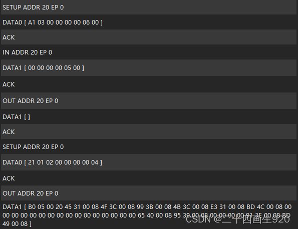
以下是逻辑分析仪抓取的DFU下载的命令截图。
- A1 03 00 00 00 00 06 00命令:DFU_GETSTATUS Request
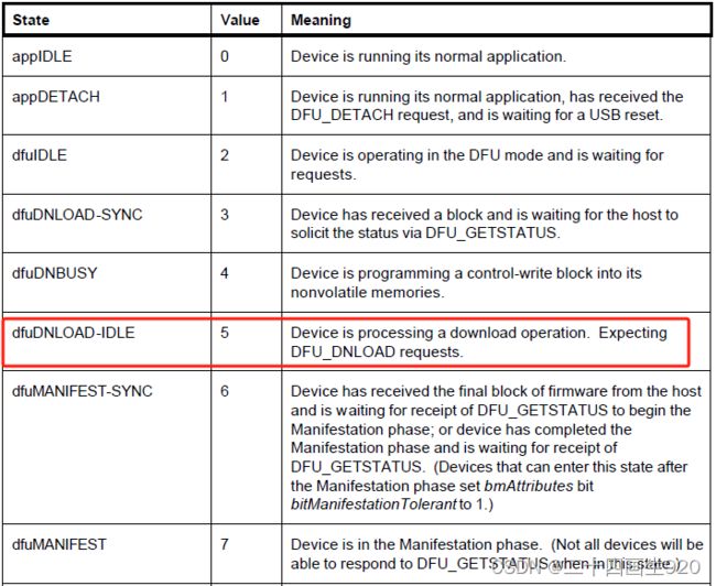
- 00 00 00 00 05 00命令:No error condition is present,Device is processing a download operation. Expecting DFU_DNLOAD requests.
- 21 01 02 00 00 00 00 04命令:向Flash写数据,长度为0x400,0x02的意思是向FLASH写数据,手册上面没有明确表示,但是程序里面有明确说明。
- B0 05 00 20 45 31 00 08 4F 3C 00 08 99 3B 00 08 4B 3C 00 08 E3 31 00 08 BD 4C 00 08 00 00 00 00 00 00 00 00 00 00 00 00 00 00 00 00 65 40 00 08 95 39 00 08 00 00 00 00 91 3E 00 08 BD 49 00 08命令:这是一条FLASH数据的指令。
其实我们不必太关心DFU指令,因为ST官网已经给我们封装好了,如果我们需要增加指令或者开辟新的FLASH,我们就需要仔细研究一下DFU命令。
3 关键函数讲解
3.1 接口函数讲解
DFU接口函数主要包括初始化FLASH、读写FLASH等函数,他们是ST官网写好的,我们直接使用即可,这里讲解一下如果FLASH改变了怎么修改接口函数。他们在dfu_mal.c文件中。
3.1.1 初始化函数讲解
我们这里只使用内部FLASH作为DFU的跳转地址,所以我们只关心《FLASH_If_Init》函数,因为内部FLASH在系统上电的时候已经被硬件初始化完成,所以这个函数直接返回真即可。
/*******************************************************************************
* Function Name  : MAL_Init
* Description    : Initializes the Media on the STM32
* Input          : None
* Output         : None
* Return         : None
*******************************************************************************/
uint16_t MAL_Init(void)
{

  FLASH_If_Init(); /* Internal Flash */

#if defined(USE_STM3210B_EVAL) || defined(USE_STM3210E_EVAL)
  SPI_If_Init();   /* SPI Flash */
#endif /* USE_STM3210B_EVAL or USE_STM3210E_EVAL */

#ifdef USE_STM3210E_EVAL
  NOR_If_Init();  /* NOR Flash */
  FSMC_NOR_ReadID(&NOR_ID);

  FSMC_NOR_ReturnToReadMode();

  /* select the alternate descriptor following NOR ID */
  if ((NOR_ID.Manufacturer_Code == 0x01)&&(NOR_ID.Device_Code2 == NOR_S29GL128))
  {
    DFU_String_Descriptor[6].Descriptor = DFU_StringInterface2_3;
  }

  /* select the alternate descriptor following NOR ID */
  if  ((NOR_ID.Manufacturer_Code == 0x20)&&(NOR_ID.Device_Code2 == NOR_M29W128G))
  {
    DFU_String_Descriptor[6].Descriptor = DFU_StringInterface2_2;
  }
#endif /* USE_STM3210E_EVAL */

  return MAL_OK;
}
3.1.2 擦除函数讲解
擦除函数也就是内部FLASH的擦写函数。
/*******************************************************************************
* Function Name  : MAL_Erase
* Description    : Erase sector
* Input          : None
* Output         : None
* Return         : None
*******************************************************************************/
uint16_t MAL_Erase(uint32_t SectorAddress)
{

  switch (SectorAddress & MAL_MASK)
  {
    case INTERNAL_FLASH_BASE:
      pMAL_Erase = FLASH_If_Erase;
      break;

#if defined(USE_STM3210B_EVAL) || defined(USE_STM3210E_EVAL)
    case SPI_FLASH_BASE:
      pMAL_Erase = SPI_If_Erase;
      break;
#endif /* USE_STM3210B_EVAL or USE_STM3210E_EVAL */

#ifdef USE_STM3210E_EVAL
    case NOR_FLASH_BASE:
      pMAL_Erase = NOR_If_Erase;
      break;
#endif /* USE_STM3210E_EVAL */

    default:
      return MAL_FAIL;
  }
  return pMAL_Erase(SectorAddress);
}
3.1.3 读函数讲解
读函数也是内部FLASH的读取函数。
/*******************************************************************************
* Function Name  : MAL_Write
* Description    : Write sectors
* Input          : None
* Output         : None
* Return         : None
*******************************************************************************/
uint16_t MAL_Write (uint32_t SectorAddress, uint32_t DataLength)
{

  switch (SectorAddress & MAL_MASK)
  {
    case INTERNAL_FLASH_BASE:
      pMAL_Write = FLASH_If_Write;
      break;

#if defined(USE_STM3210B_EVAL) || defined(USE_STM3210E_EVAL)
    case SPI_FLASH_BASE:
      pMAL_Write = SPI_If_Write;
      break;
#endif /* USE_STM3210B_EVAL || USE_STM3210E_EVAL */

#ifdef USE_STM3210E_EVAL
    case NOR_FLASH_BASE:
      pMAL_Write = NOR_If_Write;
      break;
#endif /* USE_STM3210E_EVAL */
    default:
      return MAL_FAIL;
  }
  return pMAL_Write(SectorAddress, DataLength);
}
3.1.4 写函数讲解
写函数也是内部FLASH的编程函数。
/*******************************************************************************
* Function Name  : MAL_Read
* Description    : Read sectors
* Input          : None
* Output         : None
* Return         : Buffer pointer
*******************************************************************************/
uint8_t *MAL_Read (uint32_t SectorAddress, uint32_t DataLength)
{

  switch (SectorAddress & MAL_MASK)
  {
    case INTERNAL_FLASH_BASE:
      pMAL_Read = FLASH_If_Read;
      break;

#if defined(USE_STM3210B_EVAL) || defined(USE_STM3210E_EVAL)
    case SPI_FLASH_BASE:
      pMAL_Read = SPI_If_Read;
      break;
#endif /* USE_STM3210B_EVAL or USE_STM3210E_EVAL */

#ifdef USE_STM3210E_EVAL
    case NOR_FLASH_BASE:
      pMAL_Read = NOR_If_Read;
      break;
#endif /* USE_STM3210E_EVAL */

    default:
      return 0;
  }
  return pMAL_Read (SectorAddress, DataLength);
}
3.1.5 获取状态函数讲解
获取FLASH的编程和擦除时间,这个时间可以在芯片的数据手册查看。
/*******************************************************************************
* Function Name  : MAL_GetStatus
* Description    : Get status
* Input          : None
* Output         : None
* Return         : Buffer pointer
*******************************************************************************/
uint16_t MAL_GetStatus(uint32_t SectorAddress , uint8_t Cmd, uint8_t *buffer)
{
  uint8_t x = (SectorAddress  >> 26) & 0x03 ; /* 0x000000000 --> 0 */
  /* 0x640000000 --> 1 */
  /* 0x080000000 --> 2 */

  uint8_t y = Cmd & 0x01;

#if defined(USE_STM3210E_EVAL)
  if ((x == 1) && (NOR_ID.Device_Code2 == NOR_M29W128G)&& (NOR_ID.Manufacturer_Code == 0x20))
  {
    x = 3 ;
  }
  else if((x == 1) && (NOR_ID.Device_Code2 == NOR_S29GL128) && (NOR_ID.Manufacturer_Code == 0x01))
  {
    x = 4 ;
  }
#endif /* USE_STM3210E_EVAL */

  SET_POLLING_TIMING(TimingTable[x][y]);  /* x: Erase/Write Timing */
  /* y: Media              */
  return MAL_OK;
}
3.2 GPIO配置讲解
这里对USB的D+外部上拉电阻进行了配置,如果读者使用的开发板和ST官网的外部上拉不一致,需要修改这个位置的IO口定义。这里也需要注意,ST开发板使用的是PNP型三极管作为上拉电阻的使能信号,所以这里GPIO输出低D+上拉,GPIO输出高D+为低。
![]()
![]()
![]()
3.3 中断函数讲解--USB复位函数讲解
USB复位函数十分的重要,因为在USB主机识别到设备的时候,首先发出复位指令,USB设备收到复位指令之后,会去初始化一些使用到的端点(端点0必须初始化),然后再通过相应的端点实现设备与主机间的通信。
下图是利用DSVIEW抓取的USB枚举过程的波形,每次在USB设备枚举之前,都会产生一个复位信号。
![]()
下面代码是USB复位信号来临之后,USB所做的一些事情,主要就是初始化了端点的状态,为后续枚举过程做准备,因为DFU只用到了端点0,所以这里只初始化端点0。
/*******************************************************************************
* Function Name  : DFU_Reset.
* Description    : DFU reset routine
* Input          : None.
* Output         : None.
* Return         : None.
*******************************************************************************/
void DFU_Reset(void)
{
  /* Set DFU_DEVICE as not configured */
  Device_Info.Current_Configuration = 0;

  /* Current Feature initialization */
  pInformation->Current_Feature = DFU_ConfigDescriptor[7];

  _SetBTABLE(BTABLE_ADDRESS);

  /* Initialize Endpoint 0 */
  _SetEPType(ENDP0, EP_CONTROL);
  _SetEPTxStatus(ENDP0, EP_TX_NAK);
  _SetEPRxAddr(ENDP0, ENDP0_RXADDR);
  SetEPRxCount(ENDP0, Device_Property.MaxPacketSize);
  _SetEPTxAddr(ENDP0, ENDP0_TXADDR);
  SetEPTxCount(ENDP0, Device_Property.MaxPacketSize);
  Clear_Status_Out(ENDP0);
  SetEPRxValid(ENDP0);

  /* Set this device to response on default address */
  SetDeviceAddress(0);

  /* Set the new control state of the device to Attached */
  bDeviceState = ATTACHED;
}
3.4 主函数讲解
主函数代码主要实现APP跳转的功能,通过按键跳转,如果按键为高,则跳转到APP程序,如果按键为低,则运行DFU程序。
/*******************************************************************************
* Function Name  : main.
* Description    : main routine.
* Input          : None.
* Output         : None.
* Return         : None.
*******************************************************************************/
int main(void)
{

#if defined (USE_STM32L152D_EVAL)
  FLASH_Unlock();
  FLASH_ClearFlag(FLASH_FLAG_OPTVERRUSR);
#endif
  DFU_Button_Config();

  /* Check if the Key push-button on EVAL Board is pressed
     For STM32L152-EVAL, Joystick up should be pressed */

  if (DFU_Button_Read() != 0x00)
  { /* Test if user code is programmed starting from address 0x8003000 */
    if (((*(__IO uint32_t*)ApplicationAddress) & 0x2FFE0000 ) == 0x20000000)
    { /* Jump to user application */

      JumpAddress = *(__IO uint32_t*) (ApplicationAddress + 4);
      Jump_To_Application = (pFunction) JumpAddress;
      /* Initialize user application's Stack Pointer */
      __set_MSP(*(__IO uint32_t*) ApplicationAddress);
      Jump_To_Application();
    }
  } /* Otherwise enters DFU mode to allow user to program his application */

  /* Enter DFU mode */
  DeviceState = STATE_dfuERROR;
  DeviceStatus[0] = STATUS_ERRFIRMWARE;
  DeviceStatus[4] = DeviceState;

  Set_System();
  Set_USBClock();
  USB_Init();

  /* Main loop */
  while (1)
  {}
}
4 代码演示
在运行演示之前需要做如下准备:
- 修改按键IO口
- 编译一个地址偏移为0x08003000的hex文件,作为APP文件,DFU作为BOOT文件
- 下载ST官网的DFU下载软件,并安装ST USB DFU驱动
4.1 修改按键IO口
我这里的按键IO是PC13,所以我把按键IO修改为PC13。
4.2 准备APP工程文件
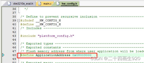
因为要实现跳转,所以首先知道DFU跳转的地址,跳转地址为0x08003000,描述符这里也应该修改为0x08003000,扇区和flash大小也要和芯片保持一致。
我们选择USB虚拟串口作为APP程序,打开虚拟串口工程,修改编译地址和中断向量表偏移地址。然后编译得到hex文件。
在下面目录下找到hex文件,保存下来。
4.3 下载DFU上位机软件
登录www.st.com官网进行下载,DFU工具下载,下载完成会自动安装DFU驱动和《Dfu file manager》《DfuSeDemo》两个应用。
下载好软件并成功安装好驱动之后,下载程序,能够在设备管理器上查看到STM Device in DFU Mode设备。
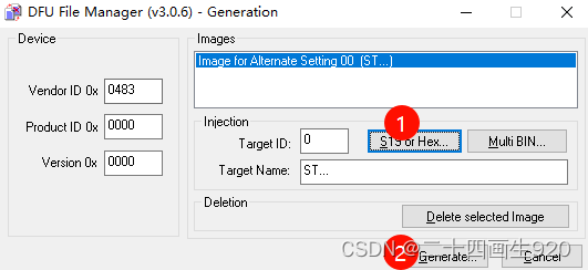
首先进行DFU文件的转换,打开《DfuSeDemo》应用程序,选择hex转dfu文件,并产生dfu文件保存。
打开《DfuSeDemo》文件,按照如图所示选择刚才生成的dfu文件,最后点击Upgrade,进行更新固件。
更新完成之后,会显示successful。
我们在《DfuSeDemo》软件能够看到Upload,Upload的意思把芯片内部的程序upload到上位机保存下来。
4.4 运行演示
当PC13拉低后复位启动开发板,设备管理器显示STM Device in DFU Mode设备。
当PC13拉高后复位启动开发板,设备管理器显示串行设备。
接下来讲解STM32 USB的语音同步传输实验,敬请期待。。。


