CoreSight学习笔记
文章目录
- 1 Components
-
- 1.1 ROM Table
- 2 使用场景
-
- 2.1 Debug Monitor中断
-
- 2.1.1 参考资料
- 2.2 Programming the cross halt
-
- 2.2.1 编程实现
- 2.2.2 参考资料
- 2.3 CTI中断
-
- 2.3.1 编程实现
-
- 2.3.1.1 准备工作
- 2.3.1.2 触发中断
- 2.3.1.3 中断响应
- 2.3.2 参考资料
1 Components
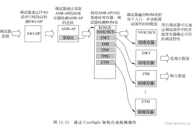
1.1 ROM Table
2 使用场景
2.1 Debug Monitor中断
- 使能中断
		// 测试debug monitor中断
		// enable debug monitor
		CoreDebug->DEMCR |= (1 << 16);
		NVIC_EnableIRQ(DebugMonitor_IRQn);
		NVIC_SetPriority(DebugMonitor_IRQn, 1);
- 实现中断响应函数
void DebugMon_Handler(void) {
		printf("DebugMon_Handler entered\n");
}

void HardFault_Handler() {
		printf("HardFault_Handler entered\n");
}
如果没有进debug monitor handler,而是进了hard fault handler,那么就说明Debug Monitor没有使能。
- 中断触发条件
程序实现软件断点,全速run起来的情况下可以进去debug monitor中断。
#if defined (TEST_SOFTWARE_BREAKPOINTS)
		// 测试软件断点
		imtprintf("start test software breakpoint.\r\n");
	    __asm("BKPT 0"); imtprintf("software breakpoint 1\r\n");
		__asm("BKPT 0"); imtprintf("software breakpoint 2\r\n");
        __asm("BKPT 0"); imtprintf("software breakpoint 3\r\n");
		__asm("BKPT 0"); imtprintf("software breakpoint 4\r\n");
	    __asm("BKPT 0"); imtprintf("software breakpoint 5\r\n");
		__asm("BKPT 0"); imtprintf("software breakpoint 6\r\n");
		__asm("BKPT 0"); imtprintf("software breakpoint 7\r\n");
		__asm("BKPT 0"); imtprintf("software breakpoint 8\r\n");
#endif
2.1.1 参考资料
[1] https://developer.arm.com/documentation/ddi0337/e/CEGHJDCF
[2] https://interrupt.memfault.com/blog/cortex-m-debug-monitor
2.2 Programming the cross halt
Cross-halt behavior happens when one processor core enters the Halting debug state, and then all the processor cores should enter the Halting debug state. This is a common situation that is encountered when debugging a system.
To generate the cross-halt behavior, the debugger must make use of the Debug Halt and Cross Halt trigger events. The debug halt event is the signal to the processor core to enter the debug state. The cross-halt event is the signal from the processor core that it is entering the debug state. To achieve the cross-halt behavior, the debugger maps the debug halt event and cross halt event signals for every processor core in the system to the same cross-trigger channel. For example, if the debugger mapped the events to Channel 3 it would program the registers as follows:
• Enable the CTI: CTICONTROL = 0b1
• Map input trigger 0 to Channel 3: CTIINEEN0 = 0b1000
• Map output trigger 0 to Channel 3: CTIINEEN0 = 0b1000
• Enable event propagation on Channel 3: CTIGATE = 0b1XXX
The following diagram illustrates how Trigger inputs 0 and Trigger outputs 0 for multiple CTI components can be mapped to channel 3 of the Cross Trigger Matrix:

注意:需要programme LAR寄存器,clear software lock。否则向CTI_CONTROL寄存器中写值的话会失效,即,值写不进去,写了在读出来还是没有变化。
2.2.1 编程实现
(1)enable trace 功能
CoreDebug -> DEMCR |= CoreDebug_DEMCR_TRCENA_Msk;
(2)清除CTI的软件访问锁
LOCK_ACCESS_REGISTER = 0xC5ACCE55
(3)enable CTI功能
CTI_CONTROL |= (1 << 0);
(4)enable要使用的channel
CTI_GATE |= (1 << 3); // 这里使用了channel 3
(5)建立trigger和channel的映射
// 这里是trigger 0 和channel 3 建立映射。
CTI_IN_EN0 |= (1 << 3);
CTI_OUT_EN0 |= (1 << 3);
2.2.2 参考资料
[1] https://developer.arm.com/documentation/102520/0100/Programming-the-cross-halt
2.3 CTI中断
CTI中断是由ctitrigout信号触发产生。 ctitrigoutack信号可以清除ctitrigout所影响的寄存器的值。
配置【Integration Test Trigger Output register, ITTRIGOUT】寄存器相应的trigger为的值为1,可以产生ctitrigout信号。channel中也可以产生ctitrigout信号,可以通过配置【CTI Application Pulse register, CTIAPPPULSE】的值,在指定的channel上产生一个channel Event,会将此event传递给相应的trigger。
配置【CTI Interrupt Acknowledge register, CTIINTACK】的值可以acknowledge ctitrigout信号。
2.3.1 编程实现
2.3.1.1 准备工作
(1)enable trace功能和CTI的功能。
(2)启用想要使用的channel。下图所示,就启用了channel 3.
(3)建立trigger和channel的映射。以K3芯片为例,只有trigger2和trigger1才能产生中断信号给中断控制器,所以下图讲trigger2和channel3绑定。
(4)使能中断
2.3.1.2 触发中断
在channel 3上面产生channel Event,即可给trigger 2发出ctitrigout信号,触发中断。
CTI_APP_PULSE |= (1 << 3);
2.3.1.3 中断响应
(1)实现中断相应函数
(2)在相应函数中清除中断。避免频繁进入中断响应函数。
CTI_INT_ACK |= (1 << 2);
2.3.2 参考资料
[1] 《ARM® CoreSight™ SoC-400 Revision: r3p2 Technical Reference Manual》中CTI registers章节
