【考试不慌】ISS615 Database Mgt学习笔记(4) Logical Database Design and the Relational Model
Learning Objectives
after studying this chapter, you should be able to:
-
Concisely define each of the following key terms: relation, primary key, composite key, foreign key, null, entity integrity rule, referential integrity constraint, well-structured relation, anomaly, surrogate primary key, recursive foreign key, normalization, normal form, functional dependency, determinant, candidate key, first normal form, second normal form, partial functional dependency, third normal form, transitive dependency, synonyms, alias, homonym, and enterprise key.
-
List five properties of relations.
-
State two essential properties of a candidate key.
-
Give a concise definition of each of the following: first normal form, second normal form, and third normal form.
-
Briefly describe four problems that may arise when merging relations.
-
Transform an E-R (or EER) diagram into a logically equivalent set of relations.
-
Create relational tables that incorporate entity integrity and referential integrity constraints.
-
Use normalization to decompose a relation with anomalies into well-structured relations.
Basic definitions
The relational data model represents data in the form of tables. The relational model is based on mathematical theory and therefore has a solid theoretical foundation. However, we need only a few simple concepts to describe the relational model. Therefore, it can be easily understood and used even by those unfamiliar with the underlying theory. The relational data model consists of the following three components (Fleming and von Halle, 1989):
-
Data structure Data are organized in the form of tables, with rows and columns.
-
Data manipulation Powerful operations (typically implemented using the SQL
language) are used to manipulate data stored in the relations.
-
Data integrity The model includes mechanisms to specify business rules that maintain the integrity of data when they are manipulated.
Relational Data Structure
A relation is a named, two-dimensional table of data. Each relation (or table) consists of a set of named columns and an arbitrary number of unnamed rows. An attribute, consistent with its definition in Chapter 2, is a named column of a relation. Each row of a relation corresponds to a record that contains data (attribute) values for a single entity. Figure 4-1 shows an example of a relation named EMPLOYEE1. This relation contains the following attributes describing employees: EmpID, Name, DeptName, and Salary. The five rows of the table correspond to five employees. It is important to understand that the sample data in Figure 4-1 are intended to illustrate the structure of the EMPLOYEE1 relation; they are not part of the relation itself. Even if we add another row of data to the figure or change any of the data in the existing rows, it is still the same EMPLOYEE1 relation. Nor does deleting a row change the relation. In fact, we could delete all of the rows shown in Figure 4-1, and the EMPLOYEE1 relation would still exist. In other words, Figure 4-1 is an instance of the EMPLOYEE1 relation.
We can express the structure of a relation by using a shorthand notation in which the name of the relation is followed (in parentheses) by the names of the attributes in that relation. For EMPLOYEE1 we would have:
EMPLOYEE1(EmpID, Name, DeptName, Salary)
Relational Keys
We must be able to store and retrieve a row of data in a relation, based on the data values stored in that row. To achieve this goal, every relation must have a primary key. A primary key is an attribute or a combination of attributes that uniquely identifies each row in a relation. We designate a primary key by underlining the attribute name(s). For example, the primary key for the relation EMPLOYEE1 is EmpID. Notice that this attribute is underlined in Figure 4-1. In shorthand notation, we express this relation as follows:
EMPLOYEE1(EmpID, Name, DeptName, Salary)
The concept of a primary key is related to the term identifier defined in Chapter 2. The attribute or a collection of attributes indicated as an entity’s identifier in an E-R diagram may be the same attributes that comprise the primary key for the relation representing that entity. There are exceptions: For example, associative entities do not have to have an identifier, and the (partial) identifier of a weak entity forms only part of a corresponding relation’s primary key. In addition, there may be several attributes of an entity that may serve as the associated relation’s primary key. All of these situations will be illustrated later in this chapter.
A composite key is a primary key that consists of more than one attribute. For example, the primary key for a relation DEPENDENT would likely consist of the combination EmpID and DependentName. We show several examples of composite keys later in this chapter.
Often we must represent the relationship between two tables or relations. This is accomplished through the use of foreign keys. A foreign key is an attribute (possibly composite) in a relation that serves as the primary key of another relation. For example, consider the relations EMPLOYEE1 and DEPARTMENT:
EMPLOYEE1(EmpID, Name, DeptName, Salary)
DEPARTMENT(DeptName, Location, Fax)
Properties of Relations
We have defined relations as two-dimensional tables of data. However, not all tables are relations. Relations have several properties that distin- guish them from non-relational tables. We summarize these properties next:
-
Each relation (or table) in a database has a unique name.
-
An entry at the intersection of each row and column is atomic (or single valued).
There can be only one value associated with each attribute on a specific row of a
table; no multivalued attributes are allowed in a relation.
-
Each row is unique; no two rows in a relation can be identical.
-
Each attribute (or column) within a table has a unique name.
-
The sequence of columns (left to right) is insignificant. The order of the columns
in a relation can be changed without changing the meaning or use of the relation.
-
The sequence of rows (top to bottom) is insignificant. As with columns, the order
of the rows of a relation may be changed or stored in any sequence.
Removing multivalued attributes from tables
The second property of relations listed in the preceding section states that no multivalued attributes are allowed in a relation. Thus, a table that contains one or more multivalued attributes is not a relation.
For example, Figure 4-2a shows the employee data from the EMPLOYEE1 relation extended to include courses that have been taken by those employees. Because a given employee may have taken more than one course, CourseTitle and DateCompleted are multivalued attributes.
For example, the employee with EmpID 100 has taken two courses, therefore, there are two values of both CourseTitle (SPSS and Surveys) and DateCompleted (6/9/2015 and 10/7/2015) associated with one value of EmpID (100). If an employee has not taken any courses, the CourseTitle and DateCompleted attribute values are null. (See the employee with EmpID 190 for an example.)
We show how to eliminate the multivalued attributes in Figure 4-2b by filling the relevant data values into the previously vacant cells of Figure 4-2a. As a result, the table in Figure 4-2b has only single-valued attributes and now satisfies the atomic property of relations. The name EMPLOYEE2 is given to this relation to distinguish it from EMPLOYEE1. However, as you will see, this new relation does have some undesirable properties. We will discuss some of them later in the chapter, but one of them is that the primary key column EmpID no longer uniquely identifies each of the rows.
PINE VALLEY FURNITURE EXAMPLE
CUSTOMER(CustomerID, CustomerName, CustomerAddress, CustomerCity, CustomerState, CustomerPostalCode)
ORDER(OrderID, OrderDate, CustomerID)
ORDER LINE(OrderID, ProductID, OrderedQuantity)
PRODUCT(ProductID, ProductDescription, ProductFinish, ProductStandardPrice, ProductLineID)

Integrity Constraints
The relational data model includes several types of constraints, or rules limiting accept- able values and actions, whose purpose is to facilitate maintaining the accuracy and integrity of data in the database. The major types of integrity constraints are domain constraints, entity integrity, and referential integrity.
Entity Integrity
The entity integrity rule is designed to ensure that every relation has a primary key and that the data values for that primary key are all valid. In particular, it guarantees that every primary key attribute is non-null.
Domain Integrity

Referential Integrity
A referential integrity constraint is a rule that maintains consistency among the rows of two relations.
-
Referential Integrity – rule stating that any foreign key value MUST – either match a primary key value in the relation it refers to,
– or be null

Mapping EER diagrams into relations
Recap on chp 2 &3:
1. Regular entities are entities that have an independent existence and generally represent real-world objects, such as persons and products. Regular entity types are represented by rectangles with a single line.
2. Weak entities are entities that cannot exist except with an identifying rela- tionship with an owner (regular) entity type. Weak entities are identified by a rectangle with a double line.
3. Associative entities (also called gerunds) are formed from many-to-many relation- ships between other entity types. Associative entities are represented by a rectangle with rounded corners.
1st step: mapping regular entities to relations
-
Simple attributes: E-R attributes map directly onto the relation
-
Composite attributes: Use only their simple, component attributes
-
Multi-valued Attributes: Each multi-valued attribute becomes a separate relation with a foreign key taken from the superior entity
-
Derived attributes: it is not necessary to store
derived attributes in the database as their values could be derived, and we assume (in ISSS615) derived attributes are NOT stored (although they could be stored for performance reason)

2nd step: mapping weak entities
– The weak entity becomes a separate relation with a foreign key taken from the strong entity
– Primary key composed of:
• Partial identifier of weak entity
• Primary key of identifying relation (strong entity)
For each weak entity type, create a new relation and include all of the simple attributes (or simple components of composite attributes) as attributes of this relation. Then include the primary key of the identifying relation as a foreign key attribute in this new relation. The primary key of the new relation is the combination of this primary key of the identifying relation and the partial identifier of the weak entity type.
An example of this process is shown in Figure 4-11. Figure 4-11a shows the weak entity type DEPENDENT and its identifying entity type EMPLOYEE, linked by the identifying relationship Claims (see Figure 2-5). Notice that the attribute Dependent Name, which is the partial identifier for this relation, is a composite attribute with components First Name, Middle Initial, and Last Name. Thus, we assume that, for a given employee, these items will uniquely identify a dependent (a notable exception being the case of prizefighter George Foreman, who has named all his sons after himself).
Figure 4-11b shows the two relations that result from mapping this E-R segment. The primary key of DEPENDENT consists of four attributes: EmployeeID, FirstName, MiddleInitial, and LastName. DateOfBirth and Gender are the nonkey attributes. The foreign key relationship with its primary key is indicated by the arrow in the figure.
In practice, an alternative approach is often used to simplify the primary key of the DEPENDENT relation: Create a new attribute (called DependentID), which will be used as a surrogate primary key in Figure 4-11b. With this approach, the relation DEPENDENT has the following attributes:
 代理主键是数据库设计中使用的一种主键类型。与自然主键不同,自然主键是从数据本身派生的,并且具有现实世界的意义(如社会保险号或电子邮件地址),代理主键在数据中没有内在的意义。它是一个人为创建的值,通常用于数据库表中唯一标识每一行
3rd step: mapping binary relationships
-
One-to-Many - Primary key on the one side becomes a foreign key on the many side
-
Many-to-Many - Create a new relation with the primary keys of the two entities as its primary key
-
One-to-One - Primary key on the mandatory side becomes a foreign key on the optional side
Example of mapping a 1:M relationship

Example of mapping a M:N relationship
MAPPING BINARY MANT-TO-MANY RELATIONSHIP

Figure 4-13 shows an example of applying this rule. Figure 4-13a shows the Completes relationship between the entity types EMPLOYEE and COURSE from Figure 2-11a.
Figure 4-13b shows the three relations (EMPLOYEE, COURSE, and CERTIFICATE) that are formed from the entity types and the Completes relationship.
If Completes had been represented as an associative entity, as is done in Figure 2-11b, a similar result would occur, but we will deal with associative entities in a subsequent section. In the case of an M:N relationship, a relation is first created for each of the two regular entity types EMPLOYEE and COURSE. Then a new relation (named CERTIFICATE in Figure 4-13b) is created for the Completes relationship. The primary key of CERTIFICATE is the combination of EmployeeID and CourseID, which are the respective primary keys of EMPLOYEE and COURSE. As indicated in the diagram, these attributes are foreign keys that “point to” the respective primary keys. The nonkey attribute DateCompleted also appears in CERTIFICATE. Although not shown here, it is often wise to create a surrogate primary key for the CERTIFICATE relation.
MAPPING BINARY ONE-TO-ONE RELATIONSHIP

In a 1:1 relationship, the association in one direction is nearly always an optional one, whereas the association in the other direction is a mandatory one. (You can review the notation for these terms in Figure 2-1.) You should include in the relation on the optional side of the relationship a foreign key referencing the primary key of the entity type that has the mandatory participation in the 1:1 relationship. This approach will prevent the need to store null values in the foreign key attribute. Any attributes associated with the relationship itself are also included in the same relation as the foreign key.
An example of applying this procedure is shown in Figure 4-14. Figure 4-14a shows a binary 1:1 relationship between the entity types NURSE and CARE CENTER. Each care center must have a nurse who is in charge of that center. Thus, the asso- ciation from CARE CENTER to NURSE is a mandatory one, whereas the association from NURSE to CARE CENTER is an optional one (since any nurse may or may not be in charge of a care center). The attribute Date Assigned is attached to the In Charge relationship.
The result of mapping this relationship to a set of relations is shown in Figure 4-14b. The two relations NURSE and CARE CENTER are created from the two entity types. Because CARE CENTER is the optional participant, the foreign key is placed in this relation. In this case, the foreign key is NurseInCharge. It has the same domain as NurseID, and the relationship with the primary key is shown in the figure. The attribute DateAssigned is also located in CARE CENTER and would not be allowed to be null.
4th step: mapping associative entities
-
创建三个关系:首先,为参与的两个实体类型各自创建一个关系(Relation),然后为关联实体创建第三个关系。这第三个关系被称为关联关系(Associative Relation)。
-
确定主键:
- 未指定标识符:如果E-R图中没有为关联实体指定标识符,则关联关系的默认主键是一个复合键,由其他两个关系的主键属性组成。这些属性同时也是外键,指向其他两个关系。
– Identifier Not Assigned
• Default primary key for the association relation is composed of the primary keys of the two entities (as in many-to-many relationship)
- 指定了标识符:有时数据模型设计者会在E-R图上为关联实体类型分配单一属性标识符。这可能是因为关联实体类型有一个对最终用户来说熟悉的自然单一属性标识符,或者是因为默认标识符(由参与实体类型的标识符组成)可能无法唯一标识关联实体的实例。在这种情况下,新创建的关联关系的主键将是E-R图上分配的标识符,而参与实体类型的主键则作为外键包含在关联关系中。
– Identifier Assigned
• The assigned identifier becomes primary key
• Note: Recall that, in ER modeling, an identifier may be assigned to an associative entity
- 未指定标识符:如果E-R图中没有为关联实体指定标识符,则关联关系的默认主键是一个复合键,由其他两个关系的主键属性组成。这些属性同时也是外键,指向其他两个关系。
例如,假设有一个关联实体“订单行”(ORDER LINE),它链接了“订单”(ORDER)和“产品”(PRODUCT)实体类型。在映射结果中,将创建三个关系:订单关系、产品关系和订单行关系。如果“订单行”没有分配唯一标识符,则其主键将是订单关系和产品关系的主键属性的组合。如果为“订单行”分配了唯一标识符,则该标识符将成为订单行关系的主键,同时包含指向订单和产品的外键。
通过这种方式,多对多关系通过引入关联实体和关联关系在数据库中得到了有效的表示和处理。这种方法不仅有助于保持数据库模式的清晰和组织性,还能提高数据的一致性和完整性

Example of mapping an associative entity with an identifier

An example of this process is shown in Figure 4-16. Figure 4-16a shows the asso- ciative entity type SHIPMENT that links the CUSTOMER and VENDOR entity types. Shipment ID has been chosen as the identifier for SHIPMENT for two reasons:
-
Shipment ID is a natural identifier for this entity that is very familiar to end users.
-
The default identifier consisting of the combination of Customer ID and Vendor ID does not uniquely identify the instances of SHIPMENT. In fact, a given vendor typically makes many shipments to a given customer. Even including the attribute Date does not guarantee uniqueness, since there may be more than one shipment by a particular vendor on a given date. The surrogate key ShipmentID will, however, uniquely identify each shipment.
Two nonkey attributes associated with the SHIPMENT associative entity are Shipment Date and Shipment Amount.
The result of mapping this entity to a set of relations is shown in Figure 4-16b. The new associative relation is named SHIPMENT. The primary key is ShipmentID. CustomerID and VendorID are included as foreign keys in this relation, and ShipmentDate and ShipmentAmount are nonkey attributes. It is also possible that the designer decides as part of the logical modeling process to add a surrogate key into a relation that did not have it earlier. In these cases, it is highly recommended to update the conceptual model to keep it consistent.
5th step: mapping unary relationships
– One-to-One or One-to-Many - Recursive foreign key in the same relation
– Many-to-Many - Two relations:
• One for the entity type
• One for an associative relation in which the primary key has two attributes, both taken from the primary key of the entity
Unary one-to-many relationships
Unary many-to-many relationships

6th step: mapping ternary (and n- ary) relationships
–One relation for each entity and one for the associative entity
–Associative entity has foreign keys to each entity in the relationship
映射三元(和n元)关系:
- 创建关联关系:为链接三个(或更多)常规实体类型的关联实体类型创建一个新的关联关系。
- 确定主键:这个关系的默认主键由参与实体类型的三个(或更多)主键属性组成。在某些情况下,可能需要额外的属性来形成一个唯一的主键。这些属性充当外键,引用参与实体类型的各自主键。
- 关联实体的属性:关联实体类型的任何属性都成为新关系的属性。
例如,考虑一个表示病人接受医生治疗的三元关系,其中关联实体类型“病人治疗”具有属性“治疗日期”、“治疗时间”和“治疗结果”。在映射中,病人ID、医生ID和治疗代码成为“病人治疗”关系中的外键,这些外键组成了主键的一部分。然而,仅这三个属性不能唯一标识一个给定的治疗实例,因为一个病人可能在不同的时间接受同一个医生的相同治疗。为了解决这个问题,可以将“治疗日期”和“治疗时间”包含为主键的一部分,使得“病人治疗”的主键由五个属性组成:病人ID、医生ID、治疗代码、治疗日期和治疗时间。“治疗结果”是该关系中唯一的非键属性。
尽管这种主键在技术上是正确的,但它复杂且难以管理,容易出错。一个更好的方法是引入一个代理键,例如“治疗ID”,即唯一标识每次治疗的序列号。在这种情况下,除“治疗日期”和“治疗时间”外的所有原主键属性都成为“病人治疗”关系中的外键。另一种类似的方法是使用企业键,这在本章末尾有所描述。
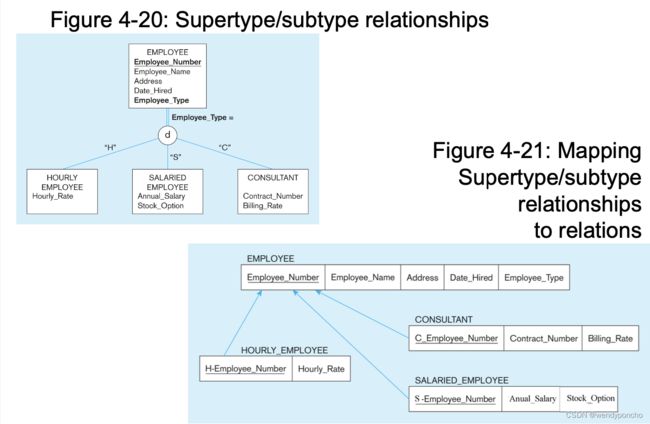
7th step: mapping Supertype/Subtype relationships
-
One relation for supertype and for each subtype
-
Supertype attributes (including identifier and subtype discriminator) go into supertype relation
-
Subtype attributes go into each subtype;
-
primary key of supertype relation also becomes primary key of subtype relation
-
1:1 relationship established between supertype and each subtype, with supertype as primary table
映射超类型/子类型关系的策略包括:
-
为超类型及其每个子类型创建单独的关系:这意味着每个类型(超类型和所有子类型)都将有其对应的表。
-
为超类型关系分配通用属性:超类型的关系包括所有成员共有的属性,包括主键。
-
为每个子类型关系分配属性:每个子类型的关系包含超类型的主键作为其外键,以及该子类型独有的属性。
-
使用超类型的一个或多个属性作为子类型鉴别器:子类型鉴别器的作用是区分不同的子类型记录(在第3章中讨论)。
举个例子,如果有一个超类型“员工”,它有三个子类型:“小时工”、“薪资工”和“顾问”。超类型的主键是“员工编号”,属性“员工类型”可以作为子类型鉴别器。
映射结果:
- 超类型关系(例如,EMPLOYEE)包含所有子类型共有的属性,包括主键“员工编号”。
- 每个子类型关系(例如,HOURLY_EMPLOYEE, SALARIED_EMPLOYEE, CONSULTANT)都包含超类型的主键作为外键(可能会使用前缀来区分,例如使用SEmployeeNumber作为薪资工的主键名称),以及该子类型独有的属性。
通过这种方式,每个子类型的记录都与一个超类型的记录相关联,确保了数据的一致性和完整性。此外,可以使用SQL命令通过连接超类型和子类型的关系来生成包含特定子类型所有属性(包括继承和特定于子类型的属性)的结果集。
这种方法处理超类型/子类型关系的优点是能够清晰地区分不同类型的数据,并保持数据结构的灵活性和扩展性。然而,它也可能导致查询操作更加复杂,因为涉及到多个表的连接。