合泰32笔记2-GPIO使用(2022/2/20)
HT-GPIO使用
1.依赖库的位置
-
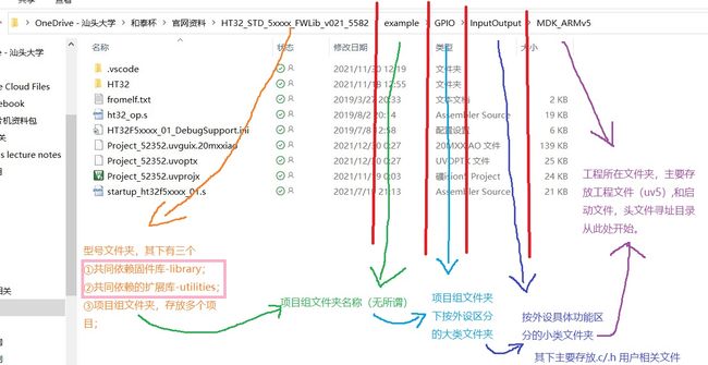
如上图:合泰的库文件的头文件在文件夹外部,且是5个上级目录的子文件内,
所以,移植时注意将合泰的源文件夹(以外设命名的文件夹)放在三级含有库的三级子文件夹内。
下图为例:
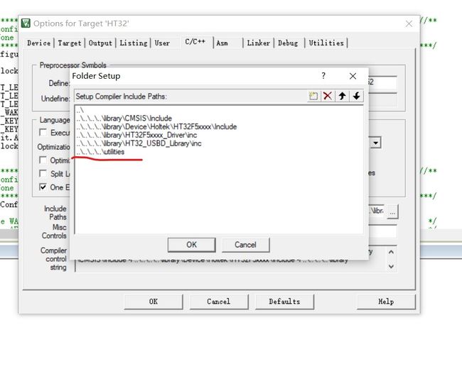
否则则需 在项目文件夹复制入两个文件夹 library 和utilities, 并修改头文件路径 。
自己写的外设.c.h文件需包含的基本头文件为如下三个:
#include "ht32.h"
#include "ht32_board.h"
#include "ht32_board_config.h"
2.GPIO使用
1.时钟配置:
-
合泰将所有板级的时钟配置寄存器(3个32位的寄存器定义为一个联合体union),且在联合体 CKCU_PeripClockConfig_TypeDef 内定义了一个32位的结构体,使我们可以在3个与时钟配置相关的32位寄存器中“可位寻址”。
-
使用时,如下:
void CKCU_Configuration(void)
{
  CKCU_PeripClockConfig_TypeDef CKCUClock = {{0}};
//定义一个 *CKCU_PeripClockConfig_TypeDef* 此类型的联合体,建议内部的结构体全部赋值2为0(关闭所有时钟)
  HTCFG_OUTPUT_LED0_CLK(CKCUClock) = 1;
  HTCFG_OUTPUT_LED1_CLK(CKCUClock) = 1;
  HTCFG_OUTPUT_LED2_CLK(CKCUClock) = 1;
  HTCFG_INPUT_WAKE_CLK(CKCUClock)  = 1;
  HTCFG_INPUT_KEY1_CLK(CKCUClock)  = 1;
  HTCFG_INPUT_KEY2_CLK(CKCUClock)  = 1;
//此处的宏定义和的访问成员操作一致,实际只是将操作宏定义而已。
  CKCUClock.Bit.AFIO       = 1;
//再将所需要的时钟以访问成员变量的形式,其中bit是联合体内 含3*32位的结构体 ,其下成员均为对应外设的时钟位,置一即该时钟的配置寄存器写入一
  CKCU_PeripClockConfig(CKCUClock, ENABLE);
//使用该使能函数将所有配置写入
}
2.GPIO输出/输入配置
-
几乎每一个IO都可以被复用为多达15种功能(GPIO也是功能之一),所以建议在使用前均使用复用功能配置函数配置好IO对应的内部功能。
/*********************************************************************************************************//**
 * @brief Configure alternated mode of GPIO with specified pins.
 * @param GPIO_Px: ⭐GPIO_PA ~ GPIO_PD.填写IO端口port,宏定义好的
 * @param AFIO_PIN_n: This parameter can be any combination of AFIO_PIN_x.⭐填写对应对应引脚,即我们要用的引脚
 * @param AFIO_MODE_n: This parameter can be one of the following values:对应的内部功能有如下15个选择,
 *        @arg AFIO_MODE_DEFAULT : The default I/O function
 *        @arg AFIO_MODE_1       : Alternated mode 1
 *        @arg AFIO_MODE_2       : Alternated mode 2
 *        @arg AFIO_MODE_3       : Alternated mode 3
 *        @arg AFIO_MODE_4       : Alternated mode 4
 *        @arg AFIO_MODE_5       : Alternated mode 5
 *        @arg AFIO_MODE_6       : Alternated mode 6
 *        @arg AFIO_MODE_7       : Alternated mode 7
 *        @arg AFIO_MODE_8       : Alternated mode 8
 *        @arg AFIO_MODE_9       : Alternated mode 9
 *        @arg AFIO_MODE_10      : Alternated mode 10
 *        @arg AFIO_MODE_11      : Alternated mode 11
 *        @arg AFIO_MODE_12      : Alternated mode 12
 *        @arg AFIO_MODE_13      : Alternated mode 13
 *        @arg AFIO_MODE_14      : Alternated mode 14
 *        @arg AFIO_MODE_15      : Alternated mode 15
 * @retval None

 ⭐但通常不会直接填写下面的模式几而是填写头文件中的宏定义:如下:
 ************************************************************************************************************/
void AFIO_GPxConfig(u32 GPIO_Px, u32 AFIO_PIN_n, AFIO_MODE_Enum AFIO_MODE_n)
/* Definitions of AFIO_FUN 常填写的是以下宏定义为函数功能,易读 */ #define AFIO_FUN_DEFAULT AFIO_MODE_DEFAULT /*!< Default AFIO mode */ #define AFIO_FUN_GPIO AFIO_MODE_1 /*!< AFIO mode GPIO */ #define AFIO_FUN_DAC AFIO_MODE_2 /*!< AFIO mode DAC */ #define AFIO_FUN_ADC0 AFIO_MODE_2 /*!< AFIO mode ADC0 */ #define AFIO_FUN_ADC1 AFIO_MODE_3 /*!< AFIO mode ADC1 */ #define AFIO_FUN_CMP AFIO_MODE_3 /*!< AFIO mode CMP */ #define AFIO_FUN_MCTM_GPTM AFIO_MODE_4 /*!< AFIO mode MCTM/GPTM */ #if (LIBCFG_AFIO_PWM_MODE4) #define AFIO_FUN_PWM AFIO_MODE_4 /*!< AFIO mode PWM */ #else #define AFIO_FUN_PWM AFIO_MODE_13 /*!< AFIO mode PWM */ #endif #define AFIO_FUN_SPI AFIO_MODE_5 /*!< AFIO mode SPI */ #define AFIO_FUN_USART_UART AFIO_MODE_6 /*!< AFIO mode USART/UART */ #define AFIO_FUN_I2C AFIO_MODE_7 /*!< AFIO mode I2C */ #define AFIO_FUN_SCI AFIO_MODE_8 /*!< AFIO mode SCI */ #define AFIO_FUN_CMP_OPA AFIO_MODE_8 /*!< AFIO mode CMP/OPA */ #define AFIO_FUN_EBI AFIO_MODE_9 /*!< AFIO mode EBI */ #define AFIO_FUN_I2S AFIO_MODE_10 /*!< AFIO mode I2S */ #if (LIBCFG_AFIO_SCTM_MODE9) #define AFIO_FUN_SCTM AFIO_MODE_9 /*!< AFIO mode SCTM */ #else #define AFIO_FUN_SCTM AFIO_MODE_13 /*!< AFIO mode SCTM */ #endif #define AFIO_FUN_TEKY AFIO_MODE_12 /*!< AFIO mode TKEY */ #define AFIO_FUN_LCD AFIO_MODE_14 /*!< AFIO mode LCD */ #define AFIO_FUN_SLED AFIO_MODE_14 /*!< AFIO mode SLED */ #define AFIO_FUN_LEDC AFIO_MODE_14 /*!< AFIO mode LEDC */ #define AFIO_FUN_SYSTEM AFIO_MODE_15 /*!< AFIO mode System */ /* Definitions of AFIO_FUN alias */ #define AFIO_FUN_MCTM0 AFIO_FUN_MCTM_GPTM #define AFIO_FUN_GPTM0 AFIO_FUN_MCTM_GPTM #define AFIO_FUN_GPTM1 AFIO_FUN_MCTM_GPTM #define AFIO_FUN_GPTM2 AFIO_FUN_MCTM_GPTM #define AFIO_FUN_GPTM3 AFIO_FUN_MCTM_GPTM #define AFIO_FUN_PWM0 AFIO_FUN_PWM #define AFIO_FUN_PWM1 AFIO_FUN_PWM #define AFIO_FUN_PWM2 AFIO_FUN_PWM #define AFIO_FUN_PWM3 AFIO_FUN_PWM #define AFIO_FUN_SCTM0 AFIO_FUN_SCTM #define AFIO_FUN_SCTM1 AFIO_FUN_SCTM #define AFIO_FUN_SCTM2 AFIO_FUN_SCTM #define AFIO_FUN_SCTM3 AFIO_FUN_SCTM #define AFIO_FUN_ADC AFIO_FUN_ADC0 -
输出/入选择配置:
/*********************************************************************************************************//** * @brief Configure the direction of specified GPIO pins. * @param HT_GPIOx: where HT_GPIOx is the selected GPIO from the GPIO peripherals.⭐使用的引脚的port * @param GPIO_PIN_nBITMAP: The port pins.⭐使用的引脚的pin * This parameter can be any combination of GPIO_PIN_x. * @param GPIO_DIR_INorOUT: * This parameter can be one of below: * ⭐@arg GPIO_DIR_IN : The pins are input mode * ⭐@arg GPIO_DIR_OUT : The pins are output mode 两个模式的参数选择,对应宏就好 * @retval None ************************************************************************************************************/ void GPIO_DirectionConfig(HT_GPIO_TypeDef* HT_GPIOx, u16 GPIO_PIN_nBITMAP, GPIO_DIR_Enum GPIO_DIR_INorOUT) -
内部的上下拉电阻配置:
/*********************************************************************************************************//** * @brief Configure the pull resistor of specified GPIO pins. * @param HT_GPIOx: where HT_GPIOx is the selected GPIO from the GPIO peripherals.端口 * @param GPIO_PIN_nBITMAP: The port pins.引脚 * This parameter can be any combination of GPIO_PIN_x. * @param GPIO_PR_x: Selection of Pull resistor. * This parameter can be one of below: * @arg GPIO_PR_UP : The pins with internal pull-up resistor⭐上拉电阻宏 * @arg GPIO_PR_DOWN : The pins with internal pull-down resistor⭐下拉电阻宏 * @arg GPIO_PR_DISABLE : The pins without pull resistor * @retval None⭐开漏状态宏 ************************************************************************************************************/ void GPIO_PullResistorConfig(HT_GPIO_TypeDef* HT_GPIOx, u16 GPIO_PIN_nBITMAP, GPIO_PR_Enum GPIO_PR_x) -
输入使能设置
设置为输入时,需要多加这一步使能
/*********************************************************************************************************//**
 * @brief Enable or Disable the input control of specified GPIO pins.端口
 * @param HT_GPIOx: where HT_GPIOx is the selected GPIO from the GPIO peripherals.
 * @param GPIO_PIN_nBITMAP: The port pins.引脚
 *   This parameter can be any combination of GPIO_PIN_x.
 * @param Cmd: This parameter can be ENABLE or DISABLE.
 * @retval None使能与否
 ************************************************************************************************************/
void GPIO_InputConfig(HT_GPIO_TypeDef* HT_GPIOx, u16 GPIO_PIN_nBITMAP, ControlStatus Cmd)
3.读取输入和设置输出电平
-
使用以下函数,参数都较为简单
//读取函数:
FlagStatus GPIO_ReadInBit(HT_GPIO_TypeDef* HT_GPIOx, u16 GPIO_PIN_n);
//读取设置为输入io的电平
FlagStatus GPIO_ReadOutBit(HT_GPIO_TypeDef* HT_GPIOx, u16 GPIO_PIN_n);
//读取设置为输出io的电平
u16 GPIO_ReadInData(HT_GPIO_TypeDef* HT_GPIOx);
//读取设置为输入io的整个io组寄存器的电平
u16 GPIO_ReadOutData(HT_GPIO_TypeDef* HT_GPIOx);
//读取设置为输出io的整个组寄存器的电平
//设置函数: void GPIO_SetOutBits(HT_GPIO_TypeDef* HT_GPIOx, u16 GPIO_PIN_nBITMAP); //置一函数 void GPIO_ClearOutBits(HT_GPIO_TypeDef* HT_GPIOx, u16 GPIO_PIN_nBITMAP); //清零函数 void GPIO_WriteOutBits(HT_GPIO_TypeDef* HT_GPIOx, u16 GPIO_PIN_nBITMAP, FlagStatus Status); //设置某一位为0/1,可用定义的枚举类型代替RESET/SET /* 两个通用的枚举类型 typedef enum {RESET = 0, SET = !RESET} FlagStatus; typedef enum {ERROR = 0, SUCCESS = !ERROR} ErrStatus; */ void GPIO_WriteOutData(HT_GPIO_TypeDef* HT_GPIOx, u16 Data); //设置整组IO的输出寄存器,填入数据为u16
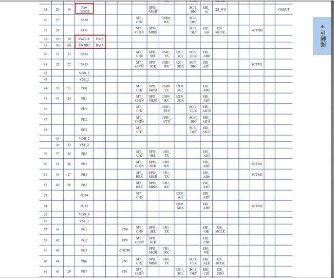
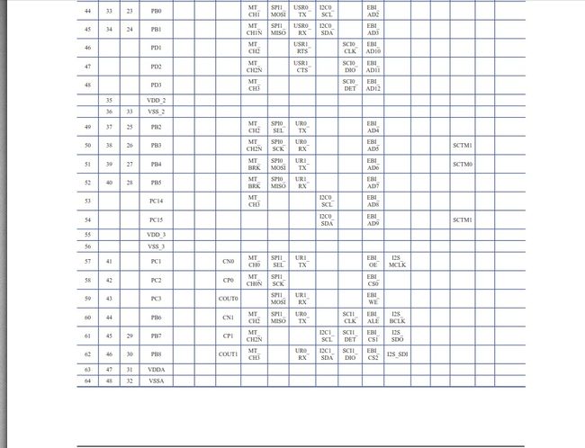
3.引脚复用功能的定义与查找
-
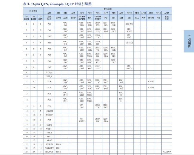
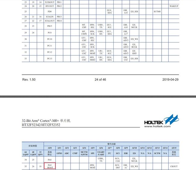
基本上合泰的引脚都建议在使用前明确复用为什么功能。避免与SW等的下载接口冲突,而造成IO没有用作想要的功能。
-
而合泰单片机引脚的复用功能表可以在数据手册(simHT32F52342_52_Datasheetv150.pdf)中查找,截图如下:
