OpenRisc-27-wishbone接口的vga ipcore的分析与仿真
引言
图形,总是给人直观的感觉。想让ORPSoC能有image/video的输出,是一件很有意义的事情,而VGA就是其中一个不错的选择。
本小节就分析一下一个wishbone接口的vga模块。
1,模块准备
下载:
http://opencores.org/project,vga_lcd
2,模块的architecture
3,模块的使用
这一步需要一点与LCD/vedio相关的知识。我曾经写过一个LCDC的linux driver,并且有数字电视的开发经验,所以理解起来就容易了很多。
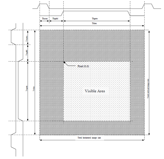
这里只把最重要的timing拿来。更过详细信息,请参考内附的spec.
下面这个图要仔细看,真正理解了才行。理解之后,后面的很多事情就好说了。
建议:想象一下,电视的刷新过程。
这个模块是比较简单的,没有复杂的图像处理功能,但是这里还是必须把下面几个概念搞明白:
1>行同步(水平同步),行宽,前肩,后肩。
2>列同步(垂直同步),场宽
3>回扫
4>像素
5>rgb
6>灰阶
7>wishbone的burst访问
8>双buffer工作机制
9>alpha blanking
10>fifo的underrun和overrun
11>调色板的本质作用
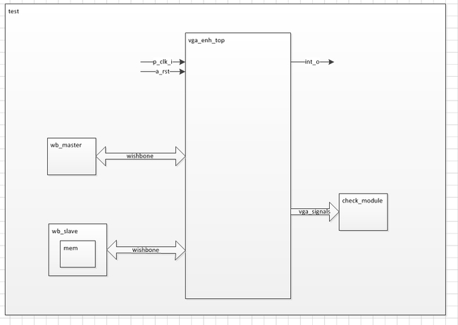
4,仿真的整体结构
要想对vga_eng_top这个模块进行仿真,需要建立必要的仿真模型,并将它们连接起来。
5,仿真过程概述
1>复位
2>测试寄存器的读写是否有问题(reg_test)
3>初始化mem。
4>测试vga所有模式下的输出时序是否正确(tim_test),共6个模式。
5>测试DVI pixel数据的正确性:dvi_pd_test
6>测试VGA pixel的数据的正确性:pd1_test
7>测试FIFO的underrun:ur_test
6,各个模式下参数的设置:
for(mode=0;mode<6;mode=mode+1)
   begin

	// reset core
	scen = 0;
	m0.wb_wr1( `CTRL,  4'hf, 32'h0000_0000);
	repeat(10)	@(posedge clk);

	$display("Mode: %0d", mode);

	case(mode)
		0:
		begin
			thsync = 0;
			thgdel = 0;
			thgate = 319; // gate = 320
			thlen = 345;

			tvsync = 0;
			tvgdel = 0;
			tvgate = 239; // vgate = 240
			tvlen = 245;

			hpol = 0;
			vpol = 0;
			cpol = 0;
			bpol = 0;
		end

		1:
		begin
			thsync = 18;
			thgdel = 18;
			thgate = 319; // gate = 320
			thlen = 390;

			tvsync = 18;
			tvgdel = 18;
			tvgate = 239; // vgate = 240
			tvlen = 290;

			hpol = 1;
			vpol = 0;
			cpol = 0;
			bpol = 0;
		end

		2:
		begin
			thsync = 1;
			thgdel = 1;
			thgate = 639; // hgate = 640
			thlen = 644;

			tvsync = 1;
			tvgdel = 1;
			tvgate = 479; // vgate = 480
			tvlen = 484;

			hpol = 0;
			vpol = 1;
			cpol = 0;
			bpol = 0;
		end

		3:
		begin
			thsync = 0;
			thgdel = 2;
			thgate = 799; // hgate = 800
			thlen = 804;

			tvsync = 0;
			tvgdel = 2;
			tvgate = 599; // vgate = 600
			tvlen = 604;

			hpol = 0;
			vpol = 0;
			cpol = 1;
			bpol = 0;
		end

		4:
		begin
			thsync = 3;
			thgdel = 2;
			thgate = 799; // hgate = 800
			thlen = 807;

			tvsync = 2;
			tvgdel = 2;
			tvgate = 599; // vgate = 600
			tvlen = 606;

			hpol = 0;
			vpol = 0;
			cpol = 0;
			bpol = 1;
		end

		5:
		begin
			thsync = 6;
			thgdel = 2;
			thgate = 799; // hgate = 800
			thlen = 810;

			tvsync = 4;
			tvgdel = 2;
			tvgate = 599; // vgate = 600
			tvlen = 608;

			hpol = 1;
			vpol = 1;
			cpol = 1;
			bpol = 1;
		end
	endcase

/*
	thsync = 0;
	thgdel = 0;
	thgate = 64;
	thlen = 70;

	tvsync = 0;
	tvgdel = 0;
	tvgate = 64;
	tvlen = 70;

	hpol = 0;
	vpol = 0;
	cpol = 0;
	bpol = 0;
*/


	m0.wb_wr1( `HTIM,  4'hf, {thsync, thgdel, thgate} );
	m0.wb_wr1( `VTIM,  4'hf, {tvsync, tvgdel, tvgate} );
	m0.wb_wr1( `HVLEN, 4'hf, {thlen, tvlen} );
	m0.wb_wr1( `CTRL,  4'hf, {
				16'h0,
				bpol, cpol,
				vpol, hpol,
				1'b0,	// PC
				2'h0,	// CD
				2'h0,	// VBL
				2'h0,	// Reserved
				5'h01	// Bank Switch, INT, VideoEn
				});

	repeat(2) @(posedge vsync);
	scen = 1;
	repeat(4) @(posedge vsync);
   end
7,仿真结果
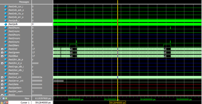
说明:仿真过程需要很长时间(我的电脑超过30mins),所以只选取了一行数据的输出波形,如下;
可以看到行同步型号,混合同步信号,blank信号,rgb信号等重要的几个信号的时序关系。
8,小结
剩下的工作就是FPGA验证了,参考之前的blog内容,将其挂在arbiter_dbus上面。
与之前那个FFT模块的接口一样,也是一个slave接口,和一个master接口。
http://blog.csdn.net/rill_zhen/article/details/8849149
附:
本实验的所有源码和文档我已上传:
http://download.csdn.net/detail/rill_zhen/5353755
good luck!


