UI定制总结
TWaver本身提供的丰富的设置选项,可以帮助我们快速实现各种绚丽的效果,但是在某些情况下,我们需要在网元上绘制一些图形来表示某种状态或业务信息,没问题,只需要一点点2D知识可以很容易实现这样的需求。
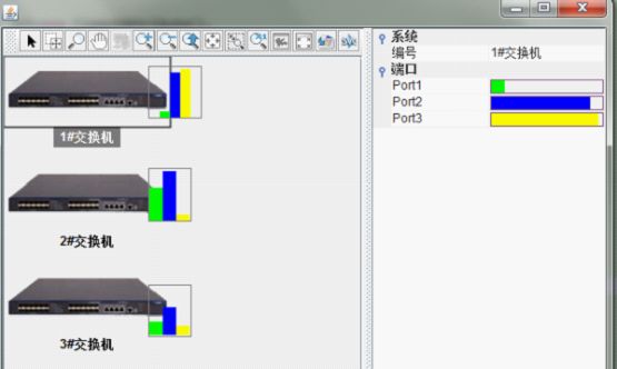
假设一种需求(仅仅是假设):监控交换机各个端口的传输速度,并用柱状图动态显示。效果图如下: 
大家可能奇怪,怎么放了三个一样的网元呢?答案是:我使用了三种方式来实现这个效果!可能还有别的方式可以实现,所谓条条大路通罗马是也!这也是TWaver的强大之处, 为我们留下了一扇门,门后就是神奇的"纳尼亚王国",本文的目的就是把这扇门的钥匙交给你。
我们从最简单的说起,TWaver提供了BarChart表示柱状图,我们可以把BarChart通过ComponentAttachment挂到Node上,这是最简单的方式,之所以说它简单,因为我们不需要使用2D绘制( 其实2D也不难),仅仅需要监听Node的属性变化然后更新BarChart即可。
ComponentAttachment上允许添加任何JComponent组件(JPanel,JButton,JLabel,JCheckbox,etc.),BarChart是JComponent的子类,自然也可以被添加。ComponentAttachment是个抽象类,需要定制一个PortRateAttachment继承ComponentAttachment
注册Attachment
TUIManager.registerAttachment("PortRateAttachment",PortRateAttachment.class);
node1.addAttachment("PortRateAttachment");
node1.putAttachmentPosition(TWaverConst.POSITION_RIGHT);
node1.putAttachmentXOffset(-20);
public class PortRateAttachment extends ComponentAttachment {
	Node p1=new Node();
	Node p2=new Node();
	Node p3=new Node();
	private BarChart barChart=new BarChart();
	public PortRateAttachment(String name, ElementUI ui) {
		super(name, ui);
		TDataBox box=new TDataBox();
		barChart.setDataBox(box);
		barChart.setShadowOffset(0);//取消阴影
		barChart.setUpperLimit(100);//刻度最大值
		barChart.setLowerLimit(0);//刻度最小值
		barChart.setYScaleLineVisible(false);//Y轴刻度线不可见
		barChart.setXAxisVisible(false);//X轴不可见
		barChart.setYAxisVisible(false);//Y轴不可见
		barChart.setBundleSize(3);//将三个Node放在一块显示
		barChart.setOpaque(false);//背景透明
		barChart.setXGap(0);//X轴Margin为0
		barChart.setYGap(0);//Y轴Margin为0
		barChart.setValueTextVisible(false);//ChartValue不可见
		barChart.getLegendPane().setVisible(false);//隐藏LegendPane

		//初始化三个Node
		p1.putChartValue(0);
		p1.putChartColor(PortRateConst.COLORS[0]);
		box.addElement(p1);

		p2.putChartValue(0);
		p2.putChartColor(PortRateConst.COLORS[1]);
		box.addElement(p2);

		p3.putChartValue(0);
		p3.putChartColor(PortRateConst.COLORS[2]);
		box.addElement(p3);

		this.setComponent(barChart);//将BarChart挂载在Attachment上
		this.setBorderVisible(true);//显示Border
		this.setBorderColor(Color.gray);//Border颜色
		this.setSize(new Dimension(50,50));//设置Attachment大小
		this.setPosition(this.element.getAttachmentPosition());//设置Attachment的位置,提前存入Node的ClientProperty
		this.setXOffset(this.element.getAttachmentXOffset());//设置Attachment的X轴偏移量,提前存入Node的ClientProperty
	}

	/*
	 * 监控Node Property变化并更新到BarChart上
	 * @see twaver.network.ui.ComponentAttachment#elementPropertyChange(java.beans.PropertyChangeEvent)
	 */
	@Override
	public void elementPropertyChange(PropertyChangeEvent evt) {
		super.elementPropertyChange(evt);
		if(evt.getNewValue()!=null){
			if("UP:p1".equals(evt.getPropertyName())){
				p1.putChartValue(Double.parseDouble(evt.getNewValue().toString().substring(3))*100);
			}else if("UP:p2".equals(evt.getPropertyName())){
				p2.putChartValue(Double.parseDouble(evt.getNewValue().toString().substring(3))*100);
			}else if("UP:p3".equals(evt.getPropertyName())){
				p3.putChartValue(Double.parseDouble(evt.getNewValue().toString().substring(3))*100);
			}
		}

	}
}
在Attachment中添加一个BarChart,并用三个Node表示chart的三个组,在elementPropertyChange中监控Node属性变化并同步更新到这三个Node上即可。
所有的代码已经加上注释,就不过多解释了
TWaver还提供了一种IconAttachment,允许我们将一个Icon作为附件挂载在Node上,我们可以在Icon上画任何内容,所以这也是一种思路(参考了TWaver官方demo,InstrumentDemo,为避免版权纠纷,特此说明 :-D )。我们定制一个PortRateIconAttachment从IconComponentAttachment继承
public class PortRateIconAttachment extends IconAttachment {
	public final static double WIDTH = 40;
	public final static double HEIGHT = 50;

	public PortRateIconAttachment(String name, ElementUI elementUI) {
		super(name, elementUI,new PortRateIcon(elementUI.getElement()));
	}

}
class PortRateIcon implements javax.swing.Icon{
	private Element element;
	public PortRateIcon(Element element){
		this.element=element;
	}
	@Override
	public void paintIcon(Component c, Graphics g, int x, int y) {
		Graphics2D g2d = (Graphics2D)g;
		//计算出柱状图中组数和组宽
    	final int count = PortRateConst.KEYS.length;
    	final double width = PortRateIconAttachment.WIDTH / count;
    	//计算坐标和尺寸,绘制三个矩形代表三个组
    	for(int i=0; i<count; i++){
    		double proportion=0;
    		if(element.getUserProperty(PortRateConst.KEYS[i])!=null)
    		    proportion =Double.parseDouble(element.getUserProperty(PortRateConst.KEYS[i]).toString().substring(3));
    		g2d.setColor(PortRateConst.COLORS[i]);
    		g2d.fillRect((int)(x + i * width),
    				(int)(y + PortRateIconAttachment.HEIGHT * (1- proportion)),
    				(int)width,(int)(PortRateIconAttachment.HEIGHT * proportion));
    	}
    	//绘制边框
    	g2d.setColor(Color.GRAY);
    	g2d.setStroke(TWaverConst.BASIC_STROKE);
    	g2d.drawRect(x, y-1, (int)PortRateIconAttachment.WIDTH, (int)PortRateIconAttachment.HEIGHT);
	}

	@Override
	public int getIconWidth() {
		return (int) PortRateIconAttachment.WIDTH;
	}

	@Override
	public int getIconHeight() {
		return (int) PortRateIconAttachment.HEIGHT;
	}

}
在PortRateIconAttachment中没有任何绘制,仅仅与一个PortRateIcon绑定,绘制工作交给PortRateIcon执行,每当PortRateIconAttachment监听到Node属性变化时就会重绘Icon
在paintIcon方法中,我们最终绘制出了我们需要的动态柱状图。
除了Attachment,重写NodeUI也是一个不错的选择。看我们的第三种方法
我们写了一个SwitchNode继承自Node,重写getUIClassID方法,实际上就是为此Node指定了UI类
PortNodeUI
public class PortNodeUI extends NodeUI {
	private Rectangle2D rect=null;
	public PortNodeUI(TNetwork network, Node node) {
		super(network, node);
	}
	@Override
	public void paintBody(Graphics2D g2d){
		super.paintBody(g2d);
    	final int count = PortRateConst.KEYS.length;
    	//计算出柱状图中组数和组宽
    	final double width = 40 / count;
    	double x=element.getX()+element.getWidth()-20;
    	double y=element.getY()+20;
    	//绘制组
    	for(int i=0; i<count; i++){
    		double proportion=0;
    		if(element.getUserProperty(PortRateConst.KEYS[i])!=null)
    			proportion =Double.parseDouble(element.getUserProperty(PortRateConst.KEYS[i]).toString().substring(3));
    		g2d.setColor(PortRateConst.COLORS[i]);
    		g2d.fillRect((int)(x + i * width),
    					(int)(y + 50 * (1- proportion)),
    					(int)width, (int)(PortRateIconAttachment.HEIGHT * proportion));
    	}
    	//绘制边框
    	g2d.setColor(Color.GRAY);
    	g2d.setStroke(TWaverConst.BASIC_STROKE);
    	g2d.drawRect((int)x, (int)y, (int)PortRateIconAttachment.WIDTH, (int)PortRateIconAttachment.HEIGHT);
	}
}
注意paintBody方法,几乎跟前面的paintIcon是一致的。
注意右侧的PropertySheet,我们也为其实现了一个Renderer绘制进度条,实际上,通过Renderer,我们可以在PropertySheet绘制任何图形或组件。
通过 ElementAttribute指定Renderer
ElementAttribute att=new ElementAttribute();
att.setRendererClass(PortRateRenderer.class.getName());
Renderer类
public class PortRateRenderer extends JComponent implements TableCellRenderer {
	private Color foreColor;
	private double proportion;
	@Override
	public Component getTableCellRendererComponent(JTable table, Object value,
			boolean isSelected, boolean hasFocus, int row, int column) {
		if(value!=null){
			String strValue=(String)value;
			for(int i=0; i<PortRateConst.KEYS.length; i++){
    			String key = PortRateConst.KEYS[i];
    			if(strValue.startsWith(key)){
    				proportion = Double.parseDouble(strValue.substring(key.length() + 1));
    				foreColor = PortRateConst.COLORS[i];
    			}
    		}
		}
		return this;
	}
	public void paintComponent(Graphics g){
		Graphics2D g2d=(Graphics2D)g;
		g2d.setColor(new Color(127,92,128));
		g2d.drawRect(1, 1, this.getWidth()-2, this.getHeight()-2);
		g2d.setColor(new Color(240,240,240));
		g2d.fillRect(2, 2, this.getWidth()-3, this.getHeight()-3);
		g2d.setColor(foreColor);
		g2d.fillRect(2, 2, (int)(this.getWidth() * proportion), this.getHeight()-3);
	}

}
在getTableCellRendererComponent中,我们根据传进Renderer的Value,设置进度条的值和前景色,在paintComponent中就可以使用了。在paintComponent里,首先画一个矩形当作进度条背景,然后覆盖一个矩形当作进度,绘制好边框以后一个进度条就完成了!
最近论坛上有人提出要实现带圆角Title的Group,贴子地址:http://twaver.servasoft.com/forum/viewtopic.php?f=4&t=3091。
帖子里的实现过程是这样的:Group的Label其实是一个LabelAttachment,为Group重新定制了一个LabelAttachment,在LabelAttachment绘制出圆角效果,然后将Group的LabelPosition设置为左上角即可。
圆角绘制的原理是将一个圆角矩形和普通矩形通过Area组合,然后用渐变色填充,具体的代码大家可以去帖子里下载。
这个专题终于可以告一段落了,熟悉TWaver架构以后,再加上一些2d知识,我们可以发挥自己的想象力绘制各种令人惊叹的效果。希望本文能起到抛砖引玉的作用。最后附上文中demo的源代码见原文最下方。