用 GNS3 做CCNA网络实验(6)
用 GNS3 做CCNA网络实验(6)
9. 路由实验: OSPF
OSPF 路由协议的优点是,它是由 IETF 领导的,不是Cisco的专有协议,因此为多数硬件路由器厂家广泛使用,而且,软件路由器(例如:Vyatta,Zebra 等)就以OSPF协议为主。所以,学习和理解OSPF的配置是很有用处的。
(1) 准备实验
我们假定是关闭 GNS3 后重新打开 GNS3 开始新的实验。
先为这次实验准备一个子目录,例如 在 gns3Project 下建一个子目录 ospf1.
在 GNS3 打开我们以前保存的已经测试过的 topology, 例如 router1.net 然后装入配置文件。
在 GNS3 菜单 File -> Save topology as 把这个 topology 改名为 ospf1.net 并保存 到 ospf1 子目录下。
在 菜单 File -> Import/Export 选 Export to a directory 把原来的配置卸出到子目录 ospf1 下。
这样,下面的实验所用到的 topology 和配置文件均保存在这个子目录下。
在这个实验,我们假定 OSPF 的 process ID 是 1, 而 area 是 0.
现在 启动各个路由器 (R1,R2,PC1,和 PC2),并打开各个 控制台 Console。
(2) 查看路由协议配置前的路由信息
R1#show ip route
R2#show ip route
(3) 配置路由器
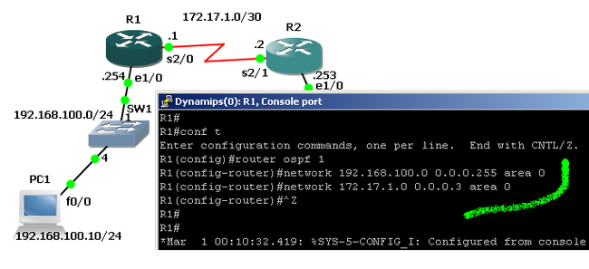
R1:
R1#
R1#conf t
Enter configuration commands, one per line.  End with CNTL/Z.
R1(config)#router ospf 1
R1(config-router)#network 192.168.100.0 0.0.0.255 area 0
R1(config-router)#network 172.17.1.0 0.0.0.3 area 0
R1(config-router)#^Z
R1#
R1#copy runn start
Destination filename [startup-config]?
Building configuration...
[OK]
R1#
*Mar  1 00:13:45.819: %OSPF-5-ADJCHG: Process 1, Nbr 192.168.110.253 on Serial2/0 from LOADING to FULL, Loading Done
R1#
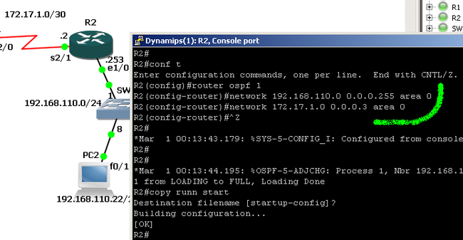
R2:
R2#
R2#conf t
Enter configuration commands, one per line.  End with CNTL/Z.
R2(config)#router ospf 1
R2(config-router)#network 192.168.110.0 0.0.0.255 area 0
R2(config-router)#network 172.17.1.0 0.0.0.3 area 0
R2(config-router)#^Z
R2#
*Mar  1 00:13:43.179: %SYS-5-CONFIG_I: Configured from console by console
R2#
*Mar  1 00:13:44.195: %OSPF-5-ADJCHG: Process 1, Nbr 192.168.100.254 on Serial2/1 from LOADING to FULL, Loading Done
R2#copy runn start
Destination filename [startup-config]?
Building configuration...
[OK]
R2#
(4) 测试
从 PC1 ping
PC1>ping 192.168.110.253

Type escape sequence to abort.
Sending 5, 100-byte ICMP Echos to 192.168.110.253, timeout is 2 seconds:
!!!!!
Success rate is 100 percent (5/5), round-trip min/avg/max = 432/773/1872 ms

PC1>ping 192.168.110.22

Type escape sequence to abort.
Sending 5, 100-byte ICMP Echos to 192.168.110.22, timeout is 2 seconds:
!!!!!
Success rate is 100 percent (5/5), round-trip min/avg/max = 596/792/892 ms
PC1>
从 PC2 ping
PC2>ping 192.168.100.254

Type escape sequence to abort.
Sending 5, 100-byte ICMP Echos to 192.168.100.254, timeout is 2 seconds:
!!!!!
Success rate is 100 percent (5/5), round-trip min/avg/max = 812/1116/1324 ms

PC2>ping 192.168.100.10

Type escape sequence to abort.
Sending 5, 100-byte ICMP Echos to 192.168.100.10, timeout is 2 seconds:
!!!!!
Success rate is 100 percent (5/5), round-trip min/avg/max = 1420/1599/1892 ms
PC2>
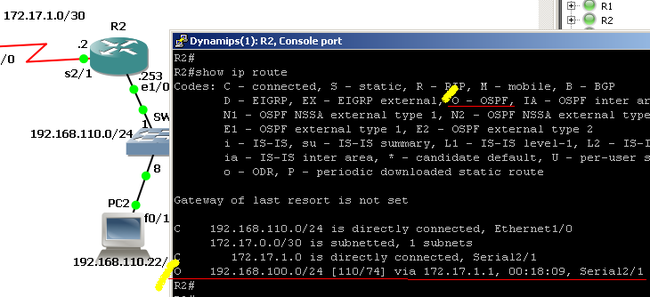
(5) 启用路由协议后的路由信息
R1:
R2:
(6) 关闭 cdp 信息
在我们的 topology 中, 由于 R1 和 R2 连接局域网段的是 Ethernet 口, 而 PC1 和 PC2 则是 FastEthernet 口,所以在控制台不断冒出 CDP 信息:
%CDP-4-DUPLEX_MISMATCH: duplex mismatch discovered on Ethernet1/0 (not full duplex), with PC1 FastEthernet0/0 (full duplex).
这信息对路由器设置和使用没有影响,但对阅读控制台的信息输出就造成混乱。关闭这个信息:
R1#conf t
Enter configuration commands, one per line.  End with CNTL/Z.
R1(config)#int e1/0
R1(config-if)#no cdp enable
R1(config-if)#^Z
R1#
在 R1 和 R2 输入如上类似的设置(端口要按实际连接来定),之后控制台就不再冒出 cdp信息。
下一步我们试试用 vpcs 做终端。
:-


